Please cite this article as: M. Jafari, A. Toloei, S. Ghasemlu, H. Parhizkar, Simulation of Strap-on Boosters Separation in the Atmosphere, International Journal of Engineering (IJE), TRANSACTIONS B: Applications Vol. 28, No. 2, (February 2015) 164-171
International Journal of Engineering
J o u r n a l H o m e p a g e : w w w . i j e . i r
Simulation of Strap-on Boosters Separation in the Atmosphere
M. Jafari*a, A. Toloeia, S. Ghasemlub, H. Parhizkarb
aDepartment of New Technologies Engineering, Shahid Beheshti University, Tehran, Iran bSpace Research Institute, Tehran, Iran
P A P E R I N F O
Paper history: Received 04 July 2014
Received in revised form 07 October 2014 Accepted 13 November 2014
Keywords:
Strap-on Boosters Separation
Numerical Dynamic-aerodynamic Interface Constraint Force Equation Methodology
A B S T R A C T
A numerical dynamic-aerodynamic interface for simulating the separation dynamics of constrained strap-on boosters jettisoned in the atmosphere is presented. The aim of the presented interface is to facilitate the simultaneous simulation of complicated dynamic separation mechanisms and full numerical CFD aerodynamic solver. A 6-DOF multi body dynamic solver using Constraint Force Equation Methodology is coupled with a numerical time dependent Euler flow solver. An automatic dynamic mesh updating procedure is employed using smoothing and local remeshing technique. This interface can simulate multi body separation problem by modeling the full separation mechanisms like springs, thrusters, joints and so on, regarding the aerodynamic effects. The flow solver is validated by the Titan-IV launch vehicle experimental data. The proposed simulated separation integration is used for a typical launch vehicle with two strap-on boosters using spring ejector mechanism and spherical constraint joints acting in the dense atmosphere.
doi: 10.5829/idosi.ije.2015.28.02b.01
1. INTRODUCTION1
Strap-on boosters are used to increase the payload capabilities of launch vehicles. By adding boosters to the rocket core, the design and manufacturing of launcher becomes more complex. One of the important issues in design and construction of these launchers is the safe booster separation from the core rocket. Any unexpected instability in this sectionor, any catastrophic collision and in general any factor that prevents successful separation, can tend the entire mission to fail. Since the booster separation usually takes place in the dense atmosphere, in addition to the dynamic effect of ejection mechanisms, aerodynamic flow around the launch vehicle is also important. Many researchers have investigated this field for several years. Meakin and Suhs from NASA Ames analyzed the solid rocket boost-er (SRB) separation of a space shuttle with a Naviboost-er–
Stokes solver, using a prescribed trajectory for dynamic
1*Corresponding Author’s Email: [email protected]
(M. Jafari)
Comm-ercial flow solvers have been of great interest in separat-ion analysis. FLUENT and OVERFLOW can be consid-ered as good paragon of these solvers that have been frequently mentioned in the literature [7, 9, 10]. Both of these solvers utilized a 6-DOF rigid body motion code with simple and prescribed separation mechanism, which is integrated into the unsteady Navier–Stokes (Euler) solver using an automated grid adoption method. In the early 2000s to develop the next generation of orbiter with reusability, the separation process was considered as one of the critical technologies [9]. For this purpose, softwares like ConSep, Sepsim using
ADAMS (Automatic Dynamic Analysis of Mechanical
Systems) solver with aide of wind tunnel results have been developed [10-12]. In such softwares, complex full separation mechanisms can be modeled but large aerodynamic coefficient databases are needed for calculation of aerodynamic effects on booster separation. In 2006, Pamadi et al. at NASA have examined the shuttle booster separation using Concep software and wind tunnel results [9]. In addition, this work has been done by the CFE/POST2 software [13].
This paper is focused on developing a dynamic/ aerodynamic coupled solver to simulate strap-on boosters separation using constraint dynamics and time dependent CFD. Therefore, two commercial solvers i.e. MscADAMS and FLUENT are integrated together with an innovative MATLAB/SIMULINK interface to constitute a powerful package that presents real time dynamic/aerodynamic coupled analysis. Independence of dynamic and aerodynamic solvers, allows the modeling of any complex separation dynamic mechanisms while the unsteady flow analysis is implemented. Consequently, this method can simulate several multi-physic problems such as booster separation with higher accuracy than the conventional methods. The effectiveness of the proposed method is evaluated in modeling of real time joint separation in the presence of unsteady aerodynamics. In addition, the interface was validated by simulating a transonic store separation event compared with experimental data obtained by the authors [14].
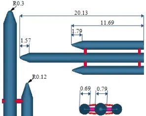
Figure 1. Launch vehicle configuration (meter)
Figure 2. Pressure distribution around the launch vehicle before the separation
2. PROBLEM DESCRIPTION
The 6-DOF dynamic separation of the strap-on boosters from the fixed core using spring ejector mechanism and spherical joints is simulated. The external geometry of the launch vehicle with springs and joint positions are shown in Figure 1.
3. LAUNCH VEHICLE AERODYNAMIC WITH STRAP-ON BOSTERS
In order to calculate the aerodynamic forces and moments, a numerical solution of unsteady flow with an implicit up wind accurate 3D Euler solver is used. A dynamic unstructured tetrahedral mesh adoption approach using combination of spring-based smoothing [3] and local remeshing [4] is automatically employed with respect to bodies motion and determines the location of new nodes. In this analysis, the entire field is totally divided into about 900000 tetrahedral cells. Sep-aration process is done at the altitude of 21 km with 4728.9 kPa gage pressure at Mach 1.6, and the air flow around the launch vehicle is assumed perfect gas. The pressure distribution in the flow field around the launch vehicle and strap-on boosters before the separation can be seen in Figure 2.
3. 1. Flow Solver Validation As a validation of flow solver, wind tunnel data of the Titan-IV was used (Figures 3, 4). In this test, the free stream Mach number is 1.6, the angle of attack is zero and the separation height is 36000 meters. In Figure 3, the calculated pressure contour for Titan-IV cross section is shown. Good agreement between the numerical solution and the wind tunnel results can be observed in most regions. Slight differences of the connecting points of the core rocket and boosters are because of a connecting cable in the wind-tunnel test.
mesh sizes. Three samples of these changes can be seen in Figure 5. The calculated pressures are roughly similar in both normal and fine cases, so the normal mesh size of about 900000 cells has been selected.
4. BOOSTERS SEPARATION DYNAMICS
The booster separation dynamics is derived using the constraint force equation (CFE) methodology. The CFE methodology provides a framework to compute the internal forces and moments acting on two bodies with specified degrees of freedom and apply them as external forces and moments to each body. Then, the motion of each body can be simulated independently like multiple free bodies. Thus, CFE methodology provides the missing link to model the stage separation [15, 16].
Figure 3. Comparison of computed surface pressure with wind-tunnel data along the centerline
Figure 4. Pressure contour around the Titan-IV launch vehicle
Figure 5. Computed surface pressure along the centerline for different grid sizes
4. 1. Separation Mechanisms Model
4. 1. 1. Separation Springs The equation used to calculate the spring force is:
=− −K(r-L0) + Fmax (1)
in which
K= spring stiffness C= viscous damping ratio R= spring displacement L0 = spring initial length
Fmax = spring initial length
The linear spring initial length is chosen as 0.9762 m, the initial force is 5000 N and the stiffness coefficient is 27000 N/m2. When spring comes into force 450 N (spring stroke is 0.167 meters), separates from the launch vehicle and its force becomes zero.
4. 1. 2. Spherical Constraint Joints Modeling Spherical constraint joints were applied to connect the boosters on the launch vehicle. For any constraint, ball and socket attachments were allocated. One of these attachments was connected to the booster (ball) and the other one was connected to the body of vehicle. The applied constraints were spherical, so the translational motion of them was limited in three dimensions, wherein there was no interference with the rotational motion. If A is pointed to the joint on the vehicle and B is pointed to the same location on the booster, one can obtain:
( , ) = 0
( , ) = 0
( , ) = 0 ∗
(2)
in which the zero function (Csep) is:
sep
1 time 0.001 sec C
0 time 0.001 sec £
ì
= í ³
î
Because of the above equation, joint1 (refer to Figure 1, right booster, up) separates from launch vehicle after 0.001 sec. The angle condition was used to disconnect the two afterward attachments. When the relative angle between booster and vehicle body reaches to one deg, the joint is disconnected.
booster main sep
booster main
1 ( - ) 1 deg C
0 ( - ) 1 deg
y y
y y
£ ì
= í ³
î
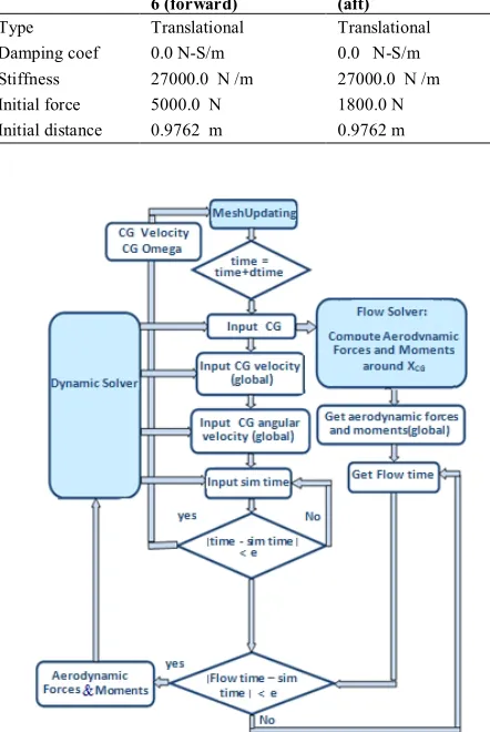
calculating the dynamic of the motion reports the position of vehicle to the flow solver, so the solver could derive the aerodynamic forces and moments in each time step. Using the results of forces and moments, this code calculates the linear and angular velocities of the vehicle. Consequently, the mesh is corrected in the next step. In this algorithm, both dynamic and aerodyna-mic solvers are connected to the main interface as two independent external functions.
TABLE 6. Mass properties Strap-on booster Launch vehicle
M : 2000.0 kg M : 22800.0 kg
IXX : 477.0 kg-m2 IYY : 19077.0 kg-m2 IZZ : 19077.0 kg-m2 IXY : 0.0 kg-m2 IZX : 0.0 kg-m2 IYZ : 0.0 kg-m IXX : 7000.0 kg-m2
IYY : 700000.0 kg-m2 IZZ : 700000.0 kg-m2 IXY : 0.0 kg-m2 IZX : 0.0 kg-m2 IYZ : 0.0 kg-m2
Without initial speed Without initial speed
TABLE 7. Characteristics of spring separation mechanism (springs 1, 2, 5 and 6 in forward section and springs 3, 4, 7 and 8 in aft section)
Number:7, 4, 3 and 8 (aft)
Number: 1, 2, 5 and 6 (forward) Spring ejectors
Translational Translational
Type
0.0 N-S/m 0.0 N-S/m
Damping coef
27000.0 N /m 27000.0 N /m
Stiffness
1800.0 N 5000.0 N
Initial force
0.9762 m 0.9762 m
Initial distance
Figure 6. The block diagram of dynamic and aerodynamic coupling
Figure 7. Variation of the right booster relative distances,
ΔX, ΔY and ΔZ (relative to the core CM) with time during
separation, in the presence of aerodynamic effects and without them
5. RESULTS
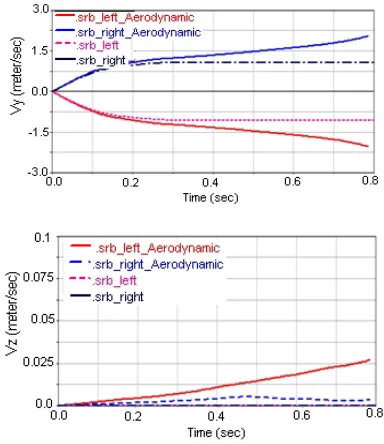
decreases. Finally, after 0.3 seconds, spring ejectors are separated and only aerodynamic effects cause rotation. So without aerodynamic effects consideration, angular velocity remains constant. The aerodynamic forces and moments variation with time can be seen in Figures 12 and 13 for the left and the right boosters, respectively. In Figure14, the pressure couture variation during booster separations and the moments of separation process are presented. The Bow shocks effect created in the top and the bottom of boosters as ejector forces can be seen in this figure. In this case, the spherical joints in the forward section cut off at 0.001 seconds after separation start. Therefore, the boosters begin to rotate about (aft) joints until the boosters reach to the angle of 1 degree (about z-axis) and then aft joints separate from the core rocket.
Figure 8. Variation of the left booster relative distances , ΔX,
ΔY and ΔZ (relative to the core CM) with time during
separation, in the presence of aerodynamic effects and without them
Figure 9. Variation of the left and right boosters relative
velocities, ΔVx, ΔVy and ΔVz (relative to the core CM) with
time during separation, in the presence of aerodynamic effects and without them
Figure 11. Variation of the left and right boosters angular velocities, p, q and r with time during separation, in the presence of aerodynamic effects and without them
Figure 12. Variation of aerodynamic forces with time on left and right boosters
Figure 13. Variation of aerodynamic moments with time on left and right boosters
6. CUNCLUSION
In this study, 6-DOF strap-on boosters separation from the launch vehicle was presented. In addition to spring ejector mechanisms and constraint joints, aerodynamic forces and moments were considered using coupled constraint dynamics and numerical aerodynamics. As mentioned, the strap-on boosters separation from launch vehicle has already been studied in the literature, but to the best of author’s knowledge, in the entire previous works just one of the dynamic motions or flow aerodynamics was simulated precisely and the others were modeled simply or as prescribed.
In this paper, the first version of the software code, named IRASEP, was presented for real-time simulation of coupled dynamics and aerodynamics of constrained strap-on boosters from launch vehicle. The ability of this interface software in connection of multi-body dynamics solver and the numerical aerodynamic solver has provided a high potential in separation simulation in the dense atmosphere.
In this simulation, two time-dependent solvers of unsteady dynamics and aerodynamics are completely independent of each other and just exchange the information through an interface software. Thus, more accurate modeling of dynamic mechanisms in the presence of unsteady aerodynamics is possible compared to conventional methods. The proposed method is proved by real-time simulation of joints in separation in the presence of unsteady aerodynamics as an example that none of the references has provided it so far. Considering diagrams and separation animations, the importance of aerodynamic effects in strap-on booster separation simulation is quite evident.
7. REFERENCES
1. Meakin, R.L. and Suhs, N.E., "Unsteady aerodynamic simulation of multiple bodies in relative motion", AIAA Paper, Vol. 1996, (1989).
2. Lochan, R., Adimurthy, V. and Kumar, K., "Separation dynamics of strap-on boosters in the atmosphere", Journal of Guidance, Control, and Dynamics, Vol. 20, No. 4, (1997), 633-639.
3. Lijewski, L.E. and Suhs, N.E., "Time-accurate computational fluid dynamics approach to transonic store separation trajectory prediction", Journal of Aircraft, Vol. 31, No. 4, (1994), 886-891.
4. Taylor, S. and Wang, J.C., "Launch-vehicle simulations using a concurrent, implicit navier-stokes solver", Journal of Spacecraft and Rockets, Vol. 33, No. 5, (1996), 601-606. 5. E Azevedo, J., Jr, P.M., Maliska, C., Marchi, C. and C. Silva,
A., "Code validation for high-speed flow simulation over satellite launch vehicle", Journal of Spacecraft and Rockets, Vol. 33, No. 1, (1996), 15-21.
6. Ko, S.-H. and Kim, C., "Separation motion of strap-on boosters with base flow and turbulence effects", Journal of Spacecraft and Rockets, Vol. 45, No. 3, (2008), 485-494.
7. Snyder, D.O., Koutsavdis, E.K. and Anttonen, J.S., "Transonic store separation using unstructured cfd with dynamic meshing",
AIAA paper, Vol. 3919, (2003).
8. Murman, S.M., Aftosmis, M.J. and Berger, M.J., "Simulations of 6-dof motion with a cartesian method", AIAA Paper, Vol. 1246, (2003).
9. Pamadi, B. N., Hotchko, N. J., Samareh, J., Covell, P. F. and Tartabini, P. V., "Simulation and analyses of multi-body separation in launch vehicle staging environment", 14th AIAA/AHI Space Planes and Hypersonic Systems and Technologies Conference AIAA, Vol. 803, (2006).
10. Murphy, K.J., Buning, P.G., Pamadi, B.N., Scallion, W.I. and Jones, K.M., "Overview of transonic to hypersonic stage separation tool development for multi-stage-to-orbit concepts",
AIAA paper, Vol. 2595, (2004).
11. Pamadi, B.N., Neirynck, T.A., Covell, P.F., Hotchko, N. and Bose, D., "Simulation and analyses of staging maneuvers of next generation reusable launch vehicles", AIAA Paper, Vol. 5185, (2004).
12. Pamadi, B.N., Neirynck, T.A., Hotcko, N.J., Scallion, W.I., Murphy, K.J. and Covell, P.F., "Simulation and analyses of stage separation of two-stage reusable launch vehicles", Journal of Spacecraft and Rockets, Vol. 44, No. 1, (2007), 66-80. 13. Pamadi, B. N., Tartabini, P. V., Toniolo, M. D., Roithmayr, C.
M., Karlgaard, C., and Samareh, J "Application of CFE/POST2 for simulation of launch vehicle stage separation", ”, NASA Langley Research Center, Hampton VA 23681.
14. Jafari, M., Toloei, A., Ghasemlu, S. and Parhizkar, H., "Simulation of store separation using low-cost cfd with dynamic meshing", International Journal of Engineering-Transactions B: Applications, Vol. 27, No. 5, (2013), 775-784.
15. Toniolo, M.D., Tartabini, P.V., Pamadi, B.N. and Hotchko, N., "Constraint force equation methodology for modeling multi-body stage separation dynamics", AIAA Paper, Vol. 219, (2008).
Simulation of Strap-on Boosters Separation in the Atmosphere
M. Jafaria, A. Toloeia, S. Ghasemlub, H. Parhizkarb
aDepartment of New Technologies Engineering, ShahidBeheshti University, Tehran, Iran bSpace Research Institute, Tehran, Iran
P A P E R I N F O
Paper history: Received 04 July 2014
Received in revised form 07 October 2014 Accepted 13 November 2014
Keywords:
Strap-on Boosters Separation
Numerical Dynamic-aerodynamic Interface Constraint Force Equation Methodology
هﺪﯿﮑﭼ
زا،ﺪﯿﻘﻣﯽﺒﻧﺎﺟيﺎﻫﺮﺘﺳﻮﺑﮏﯿﻣﺎﻨﯾدوﺮﯾآ وﮏﯿﻣﺎﻨﯾدنﺎﻣﺰﻤﻫيزﺎﺳﻪﯿﺒﺷياﺮﺑﻂﺳاويراﺰﻓا مﺮﻧﺪﮐﮏﯾﺮﺿﺎﺣﻪﻟﺎﻘﻣرد
هراﻮﻫﺎﻣ
ﺖﺳاهﺪﯾدﺮﮔﻪﺋاراﻆﯿﻠﻏﻮﺟردﺮﺑ
.
ﻞﺣﮏﯾ،رﻮﻈﻨﻣﻦﯾاﻪﺑ
زاهدﺎﻔﺘﺳاﺎﺑ،ﯽﻤﺴﺟﺪﻨﭼﮏﯿﻣﺎﻨﯾديدازآﻪﺟردﺶﺷﺮﮔ
ﺖﺳاهﺪﺷﻞﭘﻮﮐﺮﻠﯾوانﺎﯾﺮﺟنﺎﻣزﻪﺑﻪﺘﺴﺑاويدﺪﻋﺮﮕﻠﺣﮏﯾﻪﺑ،ﺪﯿﻗيوﺮﯿﻧﻪﻟدﺎﻌﻣﺪﺘﻣ
.
شورﮏﯾزا،يزﺎﺳﻪﯿﺒﺷﻦﯾارد
ﺒﻄﺗياﺮﺑ،ﯽﻌﺿﻮﻣﻪﮑﺒﺷﺪﯾﺪﺠﺗويﺮﻨﻓيزﺎﺳراﻮﻤﻫشورﮏﻤﮐﻪﺑكﺮﺤﺘﻣﻪﮑﺒﺷﯽﻧﺎﺳرزورﻪﺑ
ناﺪﯿﻣردﻢﺴﺟﺖﮐﺮﺣﻖﯿ
ﺖﺳاهﺪﺷهدﺎﻔﺘﺳارﺎﮐدﻮﺧترﻮﺻﻪﺑ،ﻪﺘﺴﺴﮔﯽﺗﺎﺒﺳﺎﺤﻣ
.
ﻂﺳاوﺪﮐ
ﺶﯾاﺪﺟيزﺎﺳﻪﯿﺒﺷﻪﺑردﺎﻗ،ﻪﻟﺎﻘﻣﻦﯾاردهﺪﺷﻪﺋارا
تاﺮﺛارﻮﻀﺣردهﺮﯿﻏ وﻞﺻﺎﻔﻣ،ﺎﻫﺮﺘﺳاﺮﺗ،ﺶﯾاﺪﺟ يﺎﻫﺮﻨﻓﺪﻨﻧﺎﻣﺶﯾاﺪﺟيﺎﻫمﺰﯿﻧﺎﮑﻣﻞﻣﺎﮐ يزﺎﺳلﺪﻣﺎﺑﻢﺴﺟﺪﻨﭼ
ﯽﻣنﺎﯾﺮﺟﮏﯿﻣﺎﻨﯾدوﺮﯾآ
ﺪﺷﺎﺑ
.
ﻞﺣ
هراﻮﻫﺎﻣيورﺮﺑدﺎﺑﻞﻧﻮﺗﺖﺴﺗﺞﯾﺎﺘﻧﮏﻤﮐﺎﺑنﺎﯾﺮﺟﺮﮔ
نﺎﺘﯿﺗﺮﺑ
4
وهﺪﺷﯽﺠﻨﺳﺖﺤﺻ
ﺎﯿﺑ
ﯽﻣنآﺐﺳﺎﻨﻣﺖﻗدﺮﮕﻧ
ﺪﺷﺎﺑ
.
هراﻮﻫﺎﻣﮏﯾياﺮﺑﺶﯾاﺪﺟيزﺎﺳﻪﯿﺒﺷ،نﺎﯾﺎﭘرد
يﺮﯿﮔرﺎﮑﺑﺎﺑوﯽﺒﻧﺎﺟﺮﺘﺳﻮﺑودﺎﺑﻪﻧﻮﻤﻧﺮﺑ
ﺖﺳاهﺪﺷﻪﺋاراﻆﯿﻠﻏﺮﻔﺴﻤﺗاردﯽﻠﺼﻔﻣتﻻﺎﺼﺗاويﺮﻨﻓﺶﯾاﺪﺟﻢﺘﺴﯿﺳ
.
ﻦﯾاردهﺪﺷﻪﺋاراﻂﺳاوﺪﮐﯽﮔﮋﯾو،ﻦﯾاﺮﺑﺎﻨﺑ
ﯽﻣارﻖﯿﻘﺤﺗ
ﻪﯿﺒﺷنﺎﮑﻣاناﻮﺗ
ﺎﮑﻣنﺎﻣﺰﻤﻫيزﺎﺳ
مﺰﯿﻧ
،ﺎﯾﺎﭘﺎﻧيدﺪﻋﮏﯿﻣﺎﻨﯾدوﺮﯾآرﻮﻀﺣردﺶﯾاﺪﺟ ﮏﯿﻣﺎﻨﯾدهﺪﯿﭽﯿﭘيﺎﻫ
ﺖﺴﻧاد