A NOVEL DATA COMPRESSION TECHNIQUE FOR
4-20 MA CURRENT LOOP TRANSMITTERS
S
.
J.
Azhari and H.
KaabiElectronic Research Center, Iran University of Science and Technology (I.U.S.T) Tehran, Iran, [email protected]
(Received: August 3, 1998 – Accepted in Final Form: March 14, 2000)
Abstract This paper presents a new data compression method for current loop transmitters. In this method, the 4-20 mA current domain is divided into some equal pieces that are used for distinct data domain with a constant relative resolution, resulting in widening the signal span. This technique eliminated the need for high resolution ADC’s or DAC’s in communication of 4-20mA current loop signals. Furthermore, because of high amplitude of current steps the sensitivity of transmitter and receiver to noise and interference is reduced. As this is a software-based technique, there is no need to change the structure of the intelligent transmitters.
Key Words Current Transmitters, Data Compression, Intelligent Transmitters, Data Decoding.
ﻩﺪﻴﻜﭼ
ﺍﺭﺪﻨﻤﺷﻮﻫ ﻲﻧﺎﻳﺮﺟﻖﻴﻗﺩﺭﺍﺰﺑﺍﻩﺪﻨﻫﺩﻝﺎﻘﺘﻧﺍ ﺭﺩﺕﺎﻋﻼﻃﺍﻱﺯﺎﺳ ﻩﺩﺮﺸﻓﻱﺍﺮﺑﺪﻳﺪﺟ ﻲﺷﻭﺭ ﻪﻟﺎﻘﻣ ﻦﻳﺍﺪﻨﻛﻲﻣﻪﺋﺍﺭﺍ
.
ﻩﺯﺎﺑ،ﺵﻭﺭﻦﻳﺍﺭﺩ 4-20mA
ﺎﻬﻧﺁﺯﺍﻡﺍﺪﻛﺮﻫﺯﺍﻭﻩﺪﺷﻢﻴﺴﻘﺗﻱﻭﺎﺴﻣﺖﻤﺴﻗﺪﻨﭼﻪﺑﺯﺎﻴﻧﺐﺴﺣﺮﺑ
ﺎﺑﻩﺪﺷﻱﺮﻴﮔﻩﺯﺍﺪﻧﺍ ﺕﺎﻋﻼﻃﺍﺯﺍﻲﺼﺨﺸﻣﻩﺩﻭﺪﺤﻣﻝﺎﺳﺭﺍ ﻱﺍﺮﺑ
ﺩﻮﺷﻲﻣﻩﺩﺎﻔﺘﺳﺍﺖﺑﺎﺛﻲﺒﺴﻧﻚﻴﻜﻔﺗﺕﺭﺪﻗ
.
ﻦﻳﺍ
ﻝﺎﻨﮕﻴﺳﻝﺎﻘﺘﻧﺍﻂﺧﻱﻭﺭﺮﺑﺩﻮﻤﻧﻲﻣﻦﻜﻤﻣﺮﻴﻏﻥﻮﻨﻛﺎﺗﻪﻛﺍﺭﻪﻫﺩﻦﻳﺪﻨﭼﻱﺎﻨﺧﺍﺮﻓﺎﺑﻝﺎﻨﮕﻴﺳﻝﺎﺳﺭﺍﻥﺎﻜﻣﺍ ﺮﻣﺍ 4-20mA ﺪﻨﻛﻲﻣﻢﻫﺍﺮﻓ
.
ﺁ ﻱﺎﻫﻝﺪﺒﻣﻪﺑ ﺵﻭﺭﻦﻳﺍ ﺭﺩ
ﺩ ﻭﺩ
ﻭﺭﻦﻳﺍ ﺯﺍ ،ﺖﺴﻴﻧﻱﺯﺎﻴﻧ ﻻﺎﺑﻚﻴﻜﻔﺗ ﺕﺭﺪﻗ ﺎﺑﺁ
ﻫﻪﻠﭘﻥﺩﻮﺑﮒﺭﺰﺑ ﻞﻴﻟﺪﺑ
ﺶﻫﺎﻛﻞﺧﺍﺪﺗﻭﺰﻳﻮﻧﻪﺑ ﺖﺒﺴﻧﻥﺁ ﻩﺪﻧﺮﻴﮔﻭﻩﺪﻨﻫﺩﻝﺎﻘﺘﻧﺍﺖﻴﺳﺎﺴﺣﻝﺎﻨﮕﻴﺳﻝﺎﺳﺭﺍ ﻱﺎ
ﺖﺳﺍﻪﺘﻓﺎﻳ
. ﺩﺭﺍﺪﻧﺩﻮﺟﻭﻲﻠﻌﻓﺪﻨﻤﺷﻮﻫﻱﺎﻫﺪﻨﻫﺩﻝﺎﻘﺘﻧﺍﺭﺎﺘﺧﺎﺳﺮﻴﻴﻐﺗﻪﺑﻱﺯﺎﻴﻧ،ﺵﻭﺭﻦﻳﺍﻥﺩﻮﺑﻱﺭﺍﺰﻓﺍﻡﺮﻧﻞﻴﻟﺪﺑ
ﺪﻨﻛﻲﻣﺖﻳﺎﻔﻛﺎﻬﻧﺁﺡﻼﺻﺍﻱﺍﺮﺑﺕﺍﺮﻴﻴﻐﺗﻝﺎﻤﻋﺍﺎﻬﻨﺗﻭ
.
INTRODUCTION
Nowadays, intelligent transmitters play a main role in instrumentation and other related industrial applications. The enhanced data processing ability in conjunction with simplicity in installation and maintenance makes them a unique system for transmission of processing signals [1].
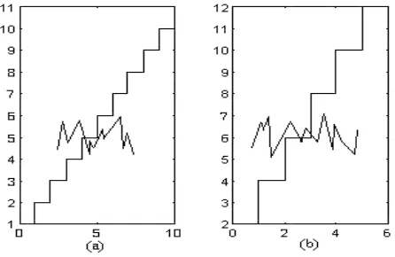
New ADC’s1 have large resolutions [2-6] that enable them to process signals with high resolution. However, unfortunately, in industrial applications, due to high levels of noise and interference, this capability becomes useless. Furthermore, as shown in Figure 1, because of the
1 Employing Σ∆ conversion techniques
constant span of 4-20mA transmitting signal, detection of low level signal steps in the presence of interfering signals is a serious difficulty. This is due to the reduction of total S/N ratio, which makes detection of signals with high resolution impossible. Thus, validity of qualitative status in relation 1 is necessary:
N n
E
Span
i
i
i
2
2int
+
<<
=
(1)Where “N” is the resolution2 of received or transmitted signal, “
i
n” is current noise and “iE” is the total error current.In instrumentation, considering all aspects
Figure 1. (a) Small steps and (b) Large steps.
(such as intrinsic S/N of ADCs & DACs and economy) the resolution of 12 bits is generally taken as the best value [7]. On the other hand, in general, there is a reverse relation between the span width and the resolution. It means that, with the same hardware and supply currents, the wider the span, the lower the resolution. Thus, designers have to tolerate a span-resolution trade off, design a more complicated hardware, and/or use higher supply signals [8]. This paper presents a method to overcome the problem as follows:
At first, the transmitted signal is compressed or merged before sending, which could then be transmitted by fewer bits using a conventional DAC (with a maximum resolution of 12-bits). At the destination, the received 4-20mA signal will be converted to a low resolution numerical value (max 12-bits), which could then be decoded to initial value with respect to transmitter signal (see Figures 2 a,b).
Nowadays there are countless techniques for compression or expansion of data in telephone communications [9-11], television broadcasting [12-13] and mass storage and processing of images [14-16].
The main goal in these applications is the reduction of bandwidth or massive data volume of speech or video signals needed for storage or transmission. In instrumentation applications, due to massive volume of data, analog commanders
[12] or high-speed digital processors [17-18] are needed.
On the other hand, due to special nature of process signals that are too slow and thus have limited bandwidth, application of above mentioned devices are not reasonable. Thus, simple algorithms proportional to the nature of process signals must be innovated to be executed by simple and slow processors existing in intelligent transmitters.
BASIC CONCEPTS
The variable to be measured can be sized with respect to the span by units. On the other hand, for displaying analog variables (by digital displays), ADCs should convert them to digital data, gaining the ability of being monitored by digital displays. In this conversion, the relationship between relative resolution3 and span can be shown by Relation 2 (see Figure 3):
n S R
10
= (2) In this relation, “n” is the number of displayed digits, “R” is relative resolution and “S” represents the span. In various applications, sufficient number of digits could be chosen according to required accuracy.
Although very high-resolution converters (ADC or DAC) are available, in practice for each measuring range, the meaningful digits are fixed. In other words, absolute resolution will vary in such a way that “R” remains constant for different measuring ranges.
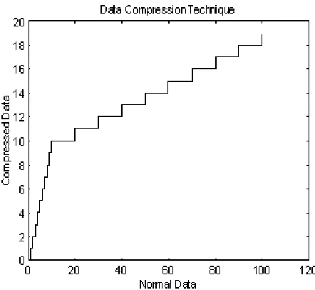
This property can be employed to merge (compress) data. In this procedure, for “n”, the most significant digits of measured variable will extracted and the least significant digits will be omitted. Figure 4, shows this procedure for a one-digit variable. Thus, for each measuring range the resolution is 10% of the related span.
(a)
(b)
Figure.2. (a) Transmitter block diagram and (b) Display unit block diagram.
This procedure can be implemented using the algorithm shown in flowchart of Figure.5. In this procedure, for the smallest range, a unit change in input variable will produce a unit change in output. While in the next upper range, each 10-unit change in input will produce a unit change in output. This relationship is valid for all successive ranges. In Figure.5 “x” is the input variable, “Y” is the compressed output variable and “n” is the most significant digits needed for displaying the variable “x”.
The “m” digit number (variable x) is expressed by (3):
0 1
1
10
10
a
a
a
x
m mm
m
⋅
+
⋅
+
+
=
− −L
(3)In which “a0-am” are integer values between 0-9. For “n”, the most significant digits of “x”4 can be extracted simply by using the proposed algorithm. It can be proved that output variable Y can be
4 Variable Y
calculated directly from (4) or (5):
0 1
1 10 10
10 Y x a a a
x m m
m m
n ⇒ = = ⋅ + ⋅ + +
< − − L (4)
− + ⋅ = ⇒
≥
∑
−=
+ p
p
k n k n
n Y p x
x 10 10 ( 10 )/10
1
0 (5)
Where “p” is a positive integer that satisfies in (6):
∑
−∑
= =
+ + ≤ <
1
0 0
10 10
p
k
p
k n k n
k x (6)
This technique reduces the volume of output variable being justified by relation (7):
x p
Y ≤( +1)⋅10n << (7)
Figure3. Relationship between span and resolution.
Figure 4. Graphical representation of compression technique.
The display unit (Figure 2b) will extract the compressed signal by an ADC. Then, an expansion algorithm, as shown in Figure 6, is employed to recover the n most significant digits of the primary variable “x”.
In this algorithm, “Y” and “X” denote the compressed and expanded variables respectively. It is shown that “X” includes the “n” most significant digits of “x”, thus:
∑
−= +
+
−
=
10
10
10
).
10
.
(
pk n k p
n
p
Y
X
(8)Hence
Figure 5. Proposed algorithm.
Figure 6. Proposed expansion algorithm.
1 1
2 2
1 1
10
10
10
10
+ − + −
+ − + − −
−
⋅
+
⋅
+
+
⋅
+
⋅
=
n m n m
n m n m m
m m m
a
a
a
a
X
L
(9) A graphical representation of this technique similar to Figure 4 is shown in Figure 75.
Figure 7. Graphical representation of data expansion technique.
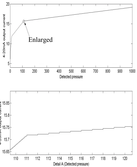
Figure 8. Data compression at transmitter side (Top) and enlarged section (Bottom).
ELATIONSHIP BETWEEN ADCS, DACS AND THE COMPRESSED VARIABLE
Using a q-bit DAC to convert the compressed signal “Y” to an analog form will result in the followings:
q n
p
1
)
10
2
(
+
⋅
≤
(11)1
10
2
⋅
−
≤
q −np
(12)n p
x
≤
10
+ (13)These expressions can be employed to determine the highest number (largest span) that can be achieved by an ADC or DAC. For example using a 12-bit DAC for a relative resolution of 0.001 will result in:
6 3 3
3 12
10
10
3
1
10
2
12
,
3
=
<
⇒
=
−
×
≤
⇒
=
=
+ −
M
p
q
n
Where M denotes the largest compressible variable. This means that communication of variables with spans up to 6 decades and relative resolution of 0.1% is achievable just by a 12-bit converter.
At this point, it must be mentioned that the compression of data by this technique can be implemented using a divider at the transmitter and a multiplier at the destination.
The difficulty is lack of a communication line to synchronize the dividing & multiplying factors in both sides. Thus, the transmitting circuit requires an additional line, which complicates the system.
SIMULATIONS AND RESULTS
In this section the results from simulation of these algorithms for sending and receiving data for a pressure variable in a wide span 0-1000 bars with a relative resolution of 0.1% by a 4-20mA transmitter are shown.
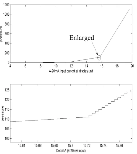
In Figure 8, the simulation for data compression technique in an intelligent transmitter is presented. It can be observed that by changing the range, the gain of DAC changes automatically by software. On the other hand, Figure 9 shows the results of expanding the data. The input data is automatically scaled and there is no need to use switching circuits for automatic range selection. This technique is employed in the design of “an Intelligent Transmitter for CO gas
E
xpan
de
d
D
at
a
Figure 9. Data expansion at display unit (Top) and enlarged section (Bottom).
concentration detection” successfully [19].
CONCLUSION
For the first time a new technique for compression of data signals of 4-20mA transmitter is proposed, which compensates for the lack of small spans of high resolution processing variables. It is important to mention that a software algorithm performs this function automatically, during the procedure of data compression and expansion, instead of employing hardware techniques for range selection.
The simulation and practical results prove the efficiency of this technique.
REFERENCES
1. Honeywell IAC., “Transmitters”, M&C Measurement & Control, Measurement Data Corp., Pittsburgh, PA, (June 1998), 199.
2. Allen, P. E. and Holberg, D. R., “Analog Integrated Circuit Design”, Persian Translation by G. Roointan Lahiji, Iran Univ. of Science and Tech., Tehran, (1375 Hej., 1997). 3. Toumazou, C., Battersby, N. and Porta, S., “Circuits and
Systems Tutorials”, IEEE Press, NJ, USA, (1996), 205-219.
4. Carley, R., “An Oversampling Analog-to-Digital
Converter Topology for High Resolution Signal Acquisition Systems”, IEEE Transactions on Circuits and Systems, (Jan. 1987), 83-91.
5. Signore, B., Kerth, D., Sooch, V and Swanson, E., “A Monolitic 20b Delta-Sigma A/D Converter”, Digest of the 1990 IEEE International Solid-State Circuit Conference, IEEE Press, NJ, (Feb. 1990), 170-171. 6. Analog Device Inc., “AD77XX Data Sheets”, Analog
CD Reference Manual, Norwood, MA., USA, (1998). 7. Operating Manual 42/61-28-5-EN, “Operating
Instructions Digitric P”, Hartmann and Braun, Frankfurt, A.G., Germany, (1994).
8. “Krone Communications Engineering”, Product Guide 6, Krone A.G., Germany, (1994).
9. Atal, B. S., “Speech Analysis and Synthesis by Linear Prediction of Speech Waveform”, J. Acoustic Soc. Am., Vol. 47, (1970).
10. Toumazou, C, Batters, N and Porta, S., "Circuts and Systems Tutorial", IEEE Press, NJ, (1996).
11. Viterbi, A. J., “Convolutional Codes and Their Performance in Communication Systems”, IEEE Trans.
Commun. Technol., Vol.COM-19, (Oct. 1971),
751-772.
12. Cattermole, K. W., “Principles of Pulse Code Modulation”, Iliffe Books Ltd., UK, (1969).
13. Kaabi, H., “Design and Implementation of High Speed ADC’s and DAC’s”, B.Sc. Thesis (in Persian), Tehran Univ., Tehran, (Mar. 1992).
14. Nakaya, Y. and Harashima, H., “ Model-Based Waveform Hybrid Coding for Low-Rate Transmission of Facial Images”, IEICE Trans. Commun., Vol. E-75-B, No. 5,. (1992), 377-384.
15. Huang, T. S., Reddy, S. and Aizawa, K., “Human Facial Motion Modeling, Analysis and Synthesis for Video Compression”, Proc. Visual Communication and Image Processing SPIE, Boston, (1991), 234-241.
16. Gerken, P., “Object-Based Analysis-Synthesis Coding at Very Low Bit Rate”, IEEE Trans. On Circuits and Systems for Video Technology, Spacial Issue on Very Low Bit Rate Video Coding, (1995).
17. Suzuki, K. et al., “A 2.4ns 16b 0.5µm CMOS Arithmetic Logic Unit for Microprogrammable Video Signal Processor”, Proceedings of IEE 1993 CICC, IEE, UK, 12.4.1-12.4.4.
18. Inoue, T. et al., “A 300MHz 16b BiCMOS Video Signal Processor”, ISSCC Digest of Technical Papers, IEEE, NJ, (Feb. 1993), 36-37.
19. H. Kaabi “Design and Manufacture of Intelligent Transmitter for Detection of CO Gas Concentration”, Msc. Thesis (in Persian), Iran Univ. of Science and Tech., Tehran, (1999).