Very Fast Field Oriented Control for Permanent Magnet
Hysteresis Synchronous Motor
H. Lesani*, A. Darabi**, Z. Nasiri Gheidari*** and F. Tootoonchian****
Abstract: In this paper, a new field oriented control scheme with maximum torque for
permanent magnet hysteresis synchronous (PMHS) motor has been presented. Vector control method provides significant improvement to the dynamic performance of ac motors but in this method d- axis current is controlled such as the ratio of motor torque to motor current is a maximum, then the dynamic performance will be very fast. Furthermore, d and q axis currents are limited such as stator winding currents remain in the allowed range. Feedback method is used for the decoupling the torque-current component from the flux-current component so these two components can be independently controlled. Simulation results for the motor are given and test results validate the theoretical performances.
Keywords: Permanent Magnet Hyateresis Motor (PMHS), Field Oriented Control,
Decoupling Method, Torque per Ampere
1 Introduction4
Hysteresis synchronous motor is widely used in small motor applications. It has some advantages such as constant torque during the run-up period, and it can pull into synchronism any load inertia that it can accelerate. Its starting current is usually less than 180% of the full-load current [1].
The combination of permanent magnet and hysteresis materials in the rotor of the hybrid motor has many distinct advantages over the conventional PM or hysteresis motors [2], [3]. The hybrid motor in which the permanent magnets are inserted into the slots at the inner surface of the hysteresis ring is called the permanent magnet hysteresis synchronous (PMHS) motor [4]. During asynchronous speed, the motor torque consists of the hysteresis torque, eddy current torque and permanent magnet brake torque. At synchronous speed the motor torque comprises of the hysteresis and
permanent magnet torques. It combines the
advantageous features of both the hysteresis and
Iranian Journal of Electrical & Electronic Engineering, 2006. Paper first received 11th November 2006 and in revised form 6th March 2007.
* Hamid Lesani is with Department of Electrical and Computer Engineering, Faculty of Engineering, University of Tehran, Tehran, Iran, E-mail:[email protected].
** Ahmad Darabi is with Faculty of Electrical and Robotic Engineering, Shahrood University of Technology, Iran.
E-mail: [email protected].
*** Zahra Nasiri-Gheidari is with Department of Electrical Engineering, Sharif University of Technology, Tehran, Iran.
E-mail: [email protected]
.
**** Farid Tootoonchian is with Department of Electrical Engineering, Iran University of Science and Technology, Tehran, Iran. E-mail: [email protected].
permanent magnet motors. The negative affect of the magnet brake torque is compensated by the eddy current torque, particularly at the initial run up period [5]. In motor drive technology, dc motors are still widely used in many applications which require precise speed control and fast dynamic response [6]. Since the dc motor has many drawbacks, such as high cost of maintenance, the use of the ac motor instead of the dc motor in adjustable speed drive system has received wide attention [7]. The field oriented control scheme [8, 9] is widely used to improve the performance of the ac motor in such a system. Using the field oriented control, the performance of the ac motor can be greatly enhanced [10 , 11].
The detailed derivation of the PMHS motor torque equation and the design of the digital speed controller for the DSP based PMHS motor vector control system is reported in [12]. But it hasn’t any decoupling technique and the d-axis stator current ids, set to zero. An analysis
and microprocessor implementation of the field oriented control scheme for a laboratory prototype PMHS motor are presented in [7] also. Reference [7] decoupled the variables of δ and stator currents ids and iqs by rotating
the stator frame to align to the rotor frame and it also used i(r)ds=0. Finally PWM vector control simulation
results for the motor drives are given in [13] as a section of paper, very briefly.
The objective of this paper is to present a mathematical model of the poly phase PMHS motors and vector control of them. Stator d-axis current is controlled such as the ratio of motor torque to motor current is a maximum, then the dynamic performance will be faster. Furthermore, this current is limited such as stator
winding currents remain in the allowed range. Feedback method is used for the decoupling the torque-current component from the flux-current component, so these two components can be independently controlled.
Finally simulation results are compared with
experimental ones of [6] that show good agreement.
2 Motor Model
The following assumptions are considered in the analysis.
a) The stator is assumed to have a sinusoidally distributed polyphase windings [4].
b) The magnetic flux is radial in the air gap and circumferential in the rotor hysteresis material [4]. c) The hysteresis effects in the rotor hysteresis materials are taken into account in the case of both running up and synchronizing operation [5].
d) The effects of saturations is neglected [5].
e) The B-H loop of the hysteresis material is modeled by a parallelogram [5].
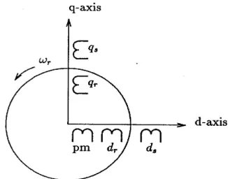
Figure 1 shows the model of a three phase PMHS motor. Each stator winding has a leakage flux and a main flux that links the rotor. The hysteresis phenomenon in an element of the rotor ring is represented by a balanced polyphase winding, and therefore by two orthogonal closed coils, each with the same number of turns as the stator coil pair.
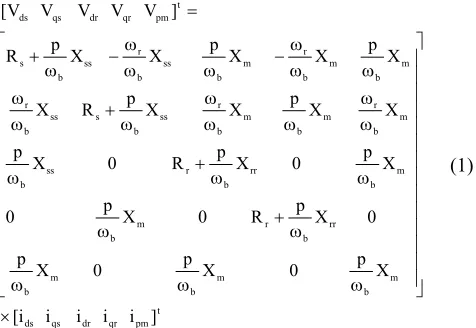
The stator variables are transformed to the rotor reference frame which eliminates the time-varying inductances in the voltage equations. Park’s equations are obtained by setting the speed of the stator frame equal to the rotor speed. The voltage-current equations are as shown in Eq. (1).
t pm qr dr qs ds m b m b m b rr b r m b m b rr b r ss b m b r m b m b r ss b s ss b r m b m b r m b ss b r ss b s t pm qr dr qs ds ] i i i i i [ X p 0 X p 0 X p 0 X p R 0 X p 0 X p 0 X p R 0 X p X X p X X p R X X p X X p X X p R ] V V V V V [ × ω ω ω ω + ω ω ω + ω ω ω ω ω ω ω + ω ω ω ω ω − ω ω ω − ω + = (1)
The electromagnetic developed torque in a three-phase, P pole motor is given by [13]:
] i i L i i L i i ) L L [( P 2 3
Te = ds− qs ds qs+ md dr qs− mq qr ds (2)
where Vds, Vqs are d, q axis stator voltages, Vdr, Vqr are
d, q axis rotor voltages, ids, iqs are d, q axis stator
currents, idr, iqr are d, q axis rotor currents, Rs, Xss are
resistance and reactance of stator circuit, Rr, Xrr are
resistance and reactance of rotor circuit, Lmd, Lmq are
d-q axis mutual inductance between rotor and stator circuits, Lds, Lqs are d-q axis inductance of stator, ωb is
base angular frequency, ωr is rotor angular frequency,
TL is load torque, H is inertia constant, p is d/dt and P is
number of pole pairs.
The electrical equivalent circuits of the hysteresis synchronous motor are presented in [13]. The motor has a standard three-phase, four-pole stator winding. Its ratings are 208 V, 5 hp and 60 Hz. Pertinent design dimensions, the rotor hysteresis material and motor equivalent circuit parameters are given in [1].
The state equations on the rotating dq0 reference frame are introduced by considering:
] , , , [ Variable State ] , T , i , i , i , i [ Vector Output ] T , V , V , V , V [ Vector Input qr dr qs ds r e qr dr qs ds L qr dr qs ds ψ ψ ψ ψ = ω = = (3)
MATLAB and Simulink softwares are used for simulation propose.
3 Torque Expression
Torque expression for PMHS motor is given in Eq. (2). In the next step d-axis current should be calculated for torque-per-ampere current control that minimizes the copper loss.
Q-axis current can be written as a function of nominal stator current amplitude and d-axis current, as shown in Eq. (4).
2 2
2 2 2 2
ds qs s qs s ds
i +i = i ⇒ i =i −i (4)
Substituting Eq. (4) in Eq. (2) and after some algebraic operations, the Electromagnetic torque given by:
] i i L i i i L i i i ) L L [( P 2 3 T ds qr mq 2 ds 2 s dr md 2 ds 2 s ds qs ds e − − + − − = (5)
idr, iqr and nominal stator current magnitude (|is|) are
constant [7], [14]. So:
) L L ( 4 a i L i 0 i T qs ds dr md ds ds e − ± = ⇒ = ∂ ∂ (6) where:
(
)
mq ds qs qr2 s 2 qs ds 2 dr
mdi 8(L L ) i 8L (L L )i
L
a= + − − − (7)
On the other hand, calculated ids may be result the stator
winding current rise from allowed range, so it should be limited. So, stator current is compared with allowed range (3 times of rating current usually) and when it was increased, ids will be limited.
Fig. 1 d-q Axis model of PMHS motor
.
4 Results And Discussions
Complete control schematic is shown in Fig. 2. First, the phase currents are transformed to a space vector in stator–coordinates, and secondly, this space vector is transformed to a d–q axis in the rotor frame. The stator-to-rotor transformation depends on the actual rotor position. Therefore, the rotor position must be determined during every sampling cycle.
The drive is fed in such a way that the q-axis current provides the desired torque. Since the d-axis of the current vector points to the magnetization direction of the rotor pole, the d-axis current is suppressed by the corresponding controller. The drive consists of three controllers, namely, the d-axis controller, the q-axis controller, and the speed controller [13].
D-axis current reference comes from torque-per-ampere calculation block and limitation block limit the ids such
as stator winding current is remain in allowed range. Figure 3 shows the test and computed open loop speed-versus-time. Figure 3(a) and (b) shows the computed and experimental speed-versus-time responses of PMHS motor from [4] and (c) shows simulation result of [5]. It is seen that the computed speed response is smoother than the experimental result. The reason is due to the difference between the cataloged and calculated areas of the hysteresis B-H loop. Because of this, it is considered that the hysteresis torque component of the computed
torque is larger than the experimental result so that the computed time to reach at synchronous speed is shorter than the experimental one. The measured starting time is approximately 5.0 s and the computed time is about 4 s for [4] and 3.8 s for [5]. But all of these responses are open loop.
Vector control method provides significant
improvement to the dynamic performance of ac motors but in proposed method d- axis current is controlled such as the ratio of motor torque to motor current is a maximum, then the dynamic performance will be very fast. It is shown in Fig. 4. Continues line is related to conventional control method and dash line is to proposed method. Starting time is approximately 0.9 sec. for conventional and about 0.45 sec. for proposed method.
Comparison between open loop and closed loop control result shows the advantages of vector control method. The experimental speed responses of the field oriented control to a step load change at 40 Hz and 70 Hz are shown in the curves of Figs. 5(a) and 6(a), respectively from [6] and proposed method results are shown in 5(c) and 6(c). It was observed that the PMHS motor can operate smoothly in response to the step load change.
(a)
Fig. 2 PMHS motor drive vector control structure.
(b)
(c)
Fig. 3 Open Loop speed–time response. (a) Computed speed– time response [4]. (b) Test speed–time response [4]. (c) Computed speed–time response with presented method.
Fig. 4 Closed loop control speed–time response. Continues line is related to conventional control method and dash line is to proposed method.
(c)
(d)
Fig. 5 Speed and dc link current responses to step load at 40 Hz. (a) conventional control speed at 1200 rpm [6] (b) conventional control dc current [6] (c) proposed control speed (d) proposed control dc current.
(c)
(d)
Fig. 6 Speed and dc link current responses to step load at 70 Hz. (a) Conventional control speed at 2100 rpm [6] (b) conventional control dc current [6] (c) proposed control speed (d) proposed control current.
(b)
Fig. 7 speed curve of motor at frequency of 40-70-40 Hz (a) conventional control speed curve [6] (b) proposed control speed curve
Figures 5(b) and 6(b) show the experimental dc link current responses at the sudden load change test from [6] and Figs. 6(d) and 7(d) shows simulation results. It can be seen from Figs. 5(b,d) and 6(b,d) that the dc link current increased from no load to full load in about 0.25 second in conventional control method and less than 0.05 second in proposed method, which reflects a quick response of the field oriented control system to the sudden load changes.
The speed of the PMHS motor is presented in Fig. 7. The test was conducted by step frequency change from 40 Hz to 70 Hz and then returning to 40 Hz. Figure 7(a) shows the test results from [6] and Fig. 7(b) shows the proposed method result.
It can be seen from Fig. 7 the proposed method has a very fast response for step change in reference speed. Speed in conventional control increased from 1200 rpm to 2100 rpm in about 4 second [6] and approximately 0.4 second in proposed method, which reflects a quick response of the proposed control system to the sudden speed changes.
When the frequency command was changed from 70 Hz to 40 Hz, the speed response was found to be much fast in conventional control. The transient period was less than 1 second for conventional control [6] and about 0.4 second for proposed method. The response of proposed method is very faster in both acceleration and deceleration.
This asymmetrical characteristic during the
acceleration and deceleration of the PMHS motor may explain that there was a brake torque due to the permanent magnets [6].
5 Conclusion
An analytical model for a permanent magnet hysteresis hybrid synchronous motor has been developed. A field oriented control scheme has been successfully simulated and a new strategy for calculating d-axis current for maximum torque-per-amper is proposed. Furthermore d-axis current is limited such as the stator winding current remains in allowed range.
This method causes to very fast dynamic performance of motor. Comparison between test and simulation results show the proposed method is sufficient. The simulation results have faster response and confirm the improvement of the dynamic performances using a field-oriented control with maximum torque-per-amper strategy.
References
[1] M. A. Rahman, A. Osheiba, “Dynamic
Performance Prediction of Polyphase Hysteresis Motors”, IEEE Trans. Industry Applications, vol. 26, no 6. Nov./Dec. 1990.
[2] M. A. Rahman, R. Qin, “Starting and
Synchronization of Permanent Magnet Hysteresis
Motors”, IEEE Tran. On Industry Appli. Vol. 32,
NO. 5, pp. 1183-1189, Sep/Oct. 1996.
[3] M. A. Rahman, R. Qin, “A Permanent Magnet
Hysteresis Hybrid Synchronous Motor for Electric
Vehicles”, IEEE Tran. On Industrial Electronics,
Vol. 44, NO. 1, p. 46-53, Feb. 1997.
[4] K. Kurihara, M. A. Rahman, “Transient
Performance Analysis for Permanent-Magnet
Hysteresis Synchronous Motor”, IEEE Trans. On
Industry Applications, Vol. 40, No. 1, pp. 135-142, Jan. /Feb. 2004.
[5] H. Lesani, A. Darabi, Z. Nasiri Gheidari, “Starting
& Synchronizing Of Conventional Hysteresis Motors With Comparison of Permanent Magnet
Hysteresis Motors”, 3rd International Conference
on Technical and Physical Problems in Power Engineering (TPE-2006), May 29-31, 2006 - Gazi University, Ankara, TURKEY.
[6] Krause, P. C. Analysis of Electric Machinery,
McGraw-Hill Book Company 1986.
[7] J. Qian, M. A. Rahman, “Analysis of Field
Oriented Control for Permanent Magnet
Hysteresis Synchronous Motors”, IEEE Tran. On
Industry Applications, VOL. 29, NO. 6, Nov./Dec. 1993.
[8] Blaschke, F. “The principle of Field orientation as
Applied to the New Transvector Closed-Loop Control System for Rotating Field Machines”
IEEE/IAS Annual Conference Record, Pittsburgh, pp. 320-326, 1988.
[9] Osheiba, A. M. Qian, J., Rahman, M. A.
“Performance of Hysteresis Permanent magnet
Motors” Electric Machines and Power Systems,
Vol. 16, No. 4, pp. 265-280, 1989.
[10]Vas, P. Vector Control of ac Machines, Oxford
University Press, 1990.
[11]De Donker, R. W. and Novotny, D. W.,
“Universal Field Oriented Controller”, IEEE/IAS
Annual Conference Record, Pittsburgh, pp. 450-456, 1988.
[12]R. Qin, M. A. Rahman, “DSP Based Torque and
Speed Controls of the Permanent Magnet
Hysteresis Synchronous Motor”, IEEE
conference, 1997.
[13]M. A. Rahman, R. Qin, “A Permanent Magnet
Hysteresis Hybrid Synchronous Motor for Electric
Vehicles”, IEEE Tran. On Industrial Electronics,
Vol. 44, No. 1, Feb. 1997.
[14]S.Vaez-zadeh, Z. Nasiri-Gheidari, F.
Tootoonchian “Vector Control of IPM motor with
Maximum torque and efficiency”, ICEE
conference proceeding, Amirkabir Univ. of Tech., Tehran, Iran, May 2006.
Hamid Lesani received the M.S. degree in electrical power engineering from the University of Tehran, Iran, in 1975, and the Ph.D. degree in electrical engineering from the university of Dundee, U.K., in 1987. early in his career, he served as a Faculty Member with Mazandaran University. After obtaining the Ph.D. degree, he joined the school of electrical and computer Engineering, Faculty of Engineering, University of Tehran, where he is a professor. His teaching and research interests are design and modeling of electrical machines and power systems. Dr. Lesani is a member of IEEE, and a member of control and intelligent processing center of Excellency, University of Tehran, Iran.
Ahmad Darabi received the B.Sc. degree from University of Tehran (Iran) in 1989. And the MSc degree from Ferdowsi University of Mashhad (Iran) in 1992 both in the field of electrical power engineering. Also he received the Ph.D. degree in the field of electrical machines from Queen’s University of Belfast (UK) in 2002. Currently, he is assistant professor in the Faculty of Electrical and Robotic Engineering, Shahrood University of Technology (Iran) from 1993. His research activities include design, modeling, manufacturing and control of miniature electrical machines and generating sets.
Zahra Nasiri-Gheidari has received her B.Sc. degrees in Electrical Engineering from the Iran University of Sciences and Technology, Tehran, Iran in 2004. And she received the Master degrees in Electrical Power Engineering from the University of Tehran in Iran in 2006, graduating with First Class Honors in both of them. She is currently director of Electrical machinery Lab. in the Electrical Engineering Department of Sharif University of Technology, Tehran, Iran. Her research interests are design and modeling of electrical machines and drives.
Farid Tootoonchian has received his B.Sc. and M.Sc. degrees in Electrical Engineering from the Iran University of Sciences and Technology, Tehran, Iran in 2000 & 2007 respectively. He has done over 21 industrial projects including one national project about electrical machines over the years, and holds 5 patents. His research interest is design of small electromagnetic machines and sensors.