524 |
P a g e
DEFECT ANALYSIS OF JIG FIXTURE: A CASE
STUDY
Kapil Dev Sharma
1, Gurpreet Singh
2, Mrinal Abhinav
3ABSTRACT
The efficiency and improved productivity have come very much into focus in manufacturing companies, due to
never ending struggle to remain better than other competitors. In present competitive market, it is necessary to
produce a product at economical rate. For moderate rate, one has to reduce material cost, labour cost and
overheads of the industry. So, any manufacturing industry working with Men, Material, Machine and Methods
intends to reduce the Breakdown, Rejection, and Defects occurring to a minimal level in order to enhance its
productivity. M/s Elofic Industries is manufacturing many items like air and oil filters, coolants, Dome Nuts,
Castle Nuts, Nut Steering Knuckles, and Nut Lock Bearing etc. When the manufacturing operation of different
components were studied, it was found that, in manufacturing operation of Nut Steering Knuckle, company was
facing average 15.18% defective pieces per month. This resulted in financial loss and increased manufacturing
lead time. The defective components were found in heat treatment, blackening process, thread milling process
and also due to existing fixture clamping method. The heat treatment process accounts for maximum (10.45%)
defective components as compared to the other process/means.
Keywords: Case Study, Jig Fixture, Cause Effect Diagram, Defects, Heat Treatment
I. INTRODUCTION
At present, micro small and medium enterprises are facing difficulties because input cost (like raw material cost,
electricity cost, fuel cost and transportation cost) has increased but final product price are not increasing
accordingly. There is no space for rejection/reworking because it is a non value added activity of the company.
No customer will pay cost for this. So customer wants defect free product with economical price. An item is
considered to be defective if it fails to confirm the specifications in any of the characteristics [1]. Each characteristic that does not meet the specification is a defect. An item is defective if it contains at least one
defect.
The Cause and Effect Diagram, graphically portrays the potential causes of an effect. The causes are grouped
into categories. Common categories are manpower (personnel), materials, methods and machines. A problem
can be due to a variety of reasons or causes. The solution to the problem becomes simpler and easier if only true
causes for the problems can be identified. The diagram is also known as an Ishikawa diagram since Dr. Ishikawa
devised its first use of the diagram. Another name for the diagram is a Fishbone diagram because of its
appearance. A fixture is a device used for rapidly and accurately position (or “locate” as is the more commonly
used term) the workpiece, and support and secure it adequately such that all parts that are produced using this
525 |
P a g e
of parts that is prevalent in many modern manufacturing. There are many types of manufacturing operationssuch as various forms of heat treatment, welding, chemical treatments, and so on.
M/s Elofic Industries is manufacturing many items like Chuck Nuts, Spacers, Plugs, Dome Nuts, Castle Nuts,
Nut Steering Knuckles, and Nut Lock Bearing etc. The company has also established some vendors for the
supply of semi finished components like rough-turning, facing, drilling etc. to minimize in-house production
cost. When the manufacturing operation of different components were studied, it was found that, in
manufacturing of Nut Steering Knuckle, company was having average 15.18% defective pieces per month. The
production cost of Nut Steering Knuckle is Rs. 34/- per piece. This has lead to an urgent critical study and
analysis of the production process of Nut Steering Knuckle. Table 1 gives the month wise description of
defective pieces of nut steering knuckle.
Table 1: Defective Components Month Wise
Months
Number of components
May-13
jun-13
july-13
Aug-13
Sep-13
Oct-13
PRODUCTION 3000 3000 3500 3000 2500 2500
DEFECTIVE
COMPONENTS
467 429 482 443 412 424
Problems faced- The major reasons for rejection of Nut Steering Knuckle were as follows:
Thread Distortion: Thread found loose or tight when inspected with the help of standard thread plug gauge (M30
x 1.0- 6H). The loose threads are scraped and tight threads are kept for reworking which is a difficult work
because of hardenability of the component. This reduces the life of the tap and thereby increases the
manufacturing cost.
Breakage of knuckle: Breakage takes place in some components due to thin section (at the slotting area) of the
component.
C.R. Gagg [3] concluded that manufacturing necessitates the transformation of raw materials from their initial form into finished, functional products. This change was achieved by a variety of processes, each of which was
designed to perform a specific function in the transformation process. Implicit within the design and operation
of such processes was a required understanding of the properties of engineering materials and their specific
response to such manufacturing methods. However, various defects can be „in-built‟ during the transformation
cycle, dependent on factors such as materials, part design, processing techniques and welding techniques.
Pankaj Jalote et al. [4] described the when–who–how approach for analyzing defect data to gain a better understanding of the quality control process and identify improvement opportunities. At the component level,
the analysis provided the capability to assess strength of dependency between components, and new ways to
526 |
P a g e
internal teams effectiveness, defect detection capability of the process in early stages, and insufficientoperational profile based testing. These observations led to simple yet effective suggestions for improving the
quality control processes. J. Zackrisson et al. [5] focused on the effectiveness of the on-line quality control in the low scale industries. The basis of the study was manufacturing process of trams. The result indicates that the
quality control program demands a solid base to be effective from the beginning of its implementation.
Empirical results show that during the off-line process the lead time in the production was reduced by 50% and
the mean cycle time of the storage was decreased by 33%. Formally, quality tools were investigated as regards
the scale of the industry. A. Y. C. Nee and A. Senthil Kumar [6] determined that automation of the fixture design process can be accomplished with the use of solid modeler, an object/ rule based expert system and a
feature recognizer coupled with external analysis routines. Although the proposed framework was only capable
of solving relative simple cases based on fixture elements, it has excellent application potential in flexible
manufacturing system. X Dong et al. [7] investigated the use of features in the domain of fixture design. They developed a method to describe a machined part, intermediate work piece geometry and material properties,
machined features and their intermediate states. The information represented about the intermediate work piece
and features enables a fixture design program to determine the surfaces available for locating and supporting
and will facilitates the detection of interference between the work piece, the cutting tool and the fixture. The
representation of machining processes described the operation between intermediate work piece states and
provided the process information that allowed the generation of such information as cutting force directions.
Hiroshi Sakural [8] developed an automatic setup planning and fixture design system. Algorithmic and heuristic methods were developed to synthesize and analyze setup plan and fixture configurations. Based on the study,
the task of setup planning and fixture design was structured into a setup planning and fixture design plan. The
plan was implemented as a system that automatically plans the setup sequence and design fixture configurations
from the tolerance solid model of the finished component. He described the result of the study of the
requirements, the setup planning and fixture design plan and the result of the implementation.
II. METHODOLOGY
At M/s. Elofic Industries, components are produced as per the customer requirements. The demand for nut
steering knuckle component is fluctuating. For the defect analysis, component produced in six months (May-13
to Octr-13) were selected and the numbers of pieces which were reworked and rejected (scrap) were determined.
During manufacturing process of nut steering knuckle, two defects occurred i.e. thread distortion and breakage
of knuckle. The inspection of internal thread was carried out after every 5th piece production. Thread plug gauge
was used for internal thread checking. If thread plug gauge goes tight, it was assumed that the tool had worn and
then resharpening was done by grinder. After resharpening again resetting was done and it has been found that
527 |
P a g e
Figure 1: Fresh CutterFigure 2: Resharpened Cutter
The following types of rejection were frequently encountered in thread milling: inaccurate dimensions of the
pitch diameter, scored thread, crushed surface of the thread, shear of the thread turns, low class of the surface
roughness, inaccurate pitch of the thread, incorrect thread form, etc. The defect analysis was carried out using
Cause and Effect Diagram (Fishbone Diagram). The fishbone diagram represents meaningful relationship
between a defect and its causes. It also enables to identify, explore and graphically displays all the possible
causes related to a problem. The fishbone diagram for the defects in thread milling process is shown in Figure 3.
The fishbone diagram shows the major factors which affect the quality of the threading. The major factors
depicted in the figure are operator, machine and method. For each factor the possible causes of defect as
observed are shown. The main causes of the defects were incorrect setting up of machine tool, incorrect ground
tool angles, wear of cutting tool and faulty machine tool. This leads to the defects in component.
528 |
P a g e
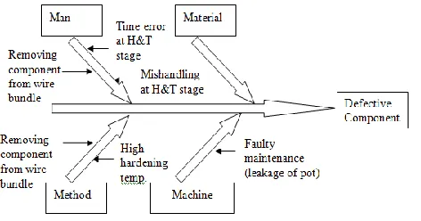
Figure 4 shows the main causes and their effects in heat treatment process. The fishbone diagram shows themajor factors which affect the quality of the threading and breakage of component. For each factor the possible
causes of defect as observed are shown. The main causes of the defects were mishandling at heat treatment
stage, removing component from wire bundle, high hardening temperature and faulty maintenance. This leads to
breakage and thread distortion problem in component.
Figure 4: Cause and Effect Diagram for Heat Treatment Process
III. RESULTS AND DISCUSSION
In thread milling process, the rejection occurred due to:
1. Incorrect setting up of cutter on the machine,
2. Incorrect cutting conditions such as depth of cut and feed rate,
3. Incorrectly ground tool angles (geometrical parameters) such as rake angle, clearance angle and nose radius,
4. Wear of cutting tool and
5. Quality of coolant.
The percentage of defective component ranges from 1.16% to 1.6%. The histogram for the above data is shown
in Figure 5. In this figure, there is a decrease in defective components from November-08 to March-09 because
of decrease in demand of the component.
Figure 5: Defective Components in Thread Milling Process
40
48 46
40 35
29
0 10 20 30 40 50 60
D
e
fe
ct
iv
e
C
o
m
p
o
n
e
n
ts
529 |
P a g e
3.1 Heat Treatment ProcessAfter thread milling process, analysis of heat treatment process was done. In heat treatment, process the
rejections were due to high hardening temperature, mishandling during opening of the component from wire
bundle and also due to less skilled operator. The percentage of defective component ranges from 9.42% to
11.52% which is very high. The histogram for the above data is shown in Figure 6.
Figure 6: Defective Components in Heat Treatment Process
3.2 Blackening Process
In blackening process, the rejections were due to heavy scaling, so it was necessary to dip the component for
more time in acid to remove the scaling. Because the section of thread was very fine, the acid affected the
thread. The percentage of defective component ranges from 2.47% to 2.77%. The histogram for the above data
is shown in Figure 7.
Figure 7: Defective Components in Blackening Process
40 48 46 40 35 29 0 10 20 30 40 50 60 D ef ec ti ve C o m p o n en ts Month 0 20 40 60 80 100
74 83 87 77 68
530 |
P a g e
3.3 Existing FixtureFor holding the component on milling machine, company was using threaded mandrel. It was taking more time for clamping the component and by operator‟s mistake the tendency of thread damage was high. This was
because of misalignment of the component and the threaded mandrel which leads to thread distortion. The
percentage of defective component is less than 1%. The histogram for the above data is shown in Figure 8.
Figure 8: Defective Components Using Existing Fixture
Figure 9 shows the types of process which causes defects in nut steering knuckle with percentage. The defective
components are in heat treatment, blackening process, thread milling process and also due to existing fixture
clamping method. The figure shows that heat treatment process accounts for maximum (10.45%) defective
components as compared to the other process/means.
Figure 9: Causes of Defects
For the rectification of these problems, following suggestions were approved by the management of the
company for implementation:
1. Modification of Manufacturing Process
2. Fixture Modification
23 24
30 22
18 20
0 5 10 15 20 25 30 35
D
ef
ec
ti
ve
C
o
m
p
o
n
en
ts
Month
Thread Milling
1.36%
Heat Treatment
10.45% Blackening
2.59% Existing
531 |
P a g e
IV. CONCLUSIONS The defective components were found in heat treatment, blackening process, thread milling process and also due to existing fixture clamping method. The heat treatment process accounts for maximum (10.45%)
defective components as compared to the other process/means.
For the rectification of these problems, following suggestions were approved by the management of the company for implementation:
- Modification of manufacturing process
- Fixture modification
In the modified process, boring, back boring, threading and grooving is done after the heat treatment i.e. the component is sent for heat treatment without threading and grooving. Boring, back boring, threading and
grooving operation is carried out on CNC turning centre.
Cycle time of boring operation on conventional lathe machine was 50 sec and on CNC machine this cycle time was reduced to 20 sec. This resulted in 60% reduction of machining time. For back boring, cycle time
was 110 sec and on CNC machine total cycle time was 30 sec. Similarly, for grooving and threading, the
cycle time was reduced to 30 sec and 35 sec respectively.
Reduction in labour by using modified process as boring, back boring and grooving was done on conventional lathe machine and then threading was done on special purpose machine. So these operations
were done by two workers but now boring, back boring, grooving and threading was done on CNC machine
so only one worker is required to carry out these operations.
The modified clamping method of the component for slot milling helps the company to perform the threading operation after heat treatment.
Modification in manufacturing process and fixture resulted in decrease in defective components from 15.18% to 1.00%.
REFERENCES
[1] O. P. Khanna, “Statistical Quality Control”, Dhanpat Rai Publications, New Delhi, 1st Edition, 2001.
[2] Cyril Donaldson, George H Lecain and V. C. Goold, “ Tool Deisgn”, Tata McGraw-Hill Publishing
Company Limited, New Delhi, 36th Edition, 2006.
[3] C. R. Gagg, “Failure of Components and Products by Engineered-in Defects: Case Studies”, Journal of
Engineering Failure Analysis, Vol. 12, 2005, pp. 1000-1026.
[4] Pankaj Jalote , Rajesh Munshi, Todd Probsting, “The When-Who-How Analysis of Defects for Improving the Quality Control Process”, Journal of Systems and Software, Vol. 80, 2007, pp. 584-589.
[5] J. Zackrisson, M. Franzen, M. Melbin, H. Shahnavaz, “Quality by a Step-By-Step Program in Low Scale Industries”, International Journal of Production Economics, Vol. 41, 1995, pp. 419-427.
[6] A. Y. C. Nee and A. Senthil Kumar, “A Framework for an Object/ Rule-Based Automated Fixture Design System”, Annals of CIRP, Vol. 40, No. 1, 1991, pp. 147-151.
[7] X. Dong, W.R. DeVries and M. J. Wozny, “Feature-Based Reasoning in Fixture Design”, Annals of CIRP,
Vol. 40, No. 1, 1991, pp. 111-114.
[8] Hiroshi Sakural , “Automatic Setup Planning and Fixture Design for Machining” Journal of Manufacturing