An Experimental Study On Drill Vibration, Thrust
Force And Surface Roughness In Drilling Of
SCF/Carbon Fibre Composite
B. Amar Babu, V. PandurangaduAbstract: In the present work, SCF/carbon composite was prepared with a commercially available vinylester, methyl ethyl ketone peroxide (catalyst) and cobalt napthenate (accelerator). The prepared composite is aimed to use in aircraft application. The composite is treated to improve the characteristics of SCF/Carbon. Drilling characteristics were studied for both treated and untreated composites. As per Taguchi orthogonal array of L8, eight experiments were conducted on the composites and machining characteristics like thrust force, surface roughness and amplitude of drill vibration were measured. Interaction effect of parameter on the machine characteristics was studied using response surface methodology. Analysis of variance was also used to identify significant parameters for the three machining characteristics. A multi response optimization technique was used to optimise parameters for minimization of thrust force, surface roughness and amplitude of drill vibration.
Keywords: SCF/C Composites, Drill vibration, surface roughness, Thrust Force, Optimization
————————————————————
1.
Introduction
At present, in the applications of aircrafts, composite materials have been used due to their good properties like resist corrosion and high strength-to-weight ratio etc. Drilling of composite has become critical operation due to delamination of composite while drilling. Uysal et al. [1] studied the cutting temperature of drill point and surface roughness of holes in drilling of pure polypropylene and carbon black–reinforced polypropylene. According to L27 full-factorial design, experiments were conducted and the experimental results were analysed using analysis of variance. Effect of drill point angle, cutting speed and feed on surface roughness and temperature was studied. Surface roughness was found to be decreased with increasing cutting speed at the same time the surface roughness increased with increasing feed. Cutting temperature was increased with the increase of cutting speed and decreased with increasing feed. Rakesh et al. [2] studied flexural behaviour of the glass fibre-reinforced plastic laminates while drilling hole under three point loading conditions. Experiments were conducted at different levels of cutting speed, feed rate and drill geometry and experimental results of cutting force and torque were collected. Finite element model was also used to study the machining characteristics and they were compared with experimental results. It was concluded that the drilling parameters affect the drilling forces and subsequently the drilling induced damage.
The drilling-induced damage has a significant effect on the flexural strength of GFRP laminates. Ramesh et al. [3] studied the effect of process parameters on quality characteristics for standard and specially designed drills in drilling of non laminated composites. The drilling experiments were conducted at different levels of drilling parameters on the proposed composite using carbide drills. Experimental results of thrust force, torque and damage factor were analysed using response surface methodology (RSM). It was found that the special drill performs better than the standard geometry drill for dry drilling pultruded composite. It was also observed that for a twist drill, feed is more consequential followed by speed in influencing the quality characteristics whereas for special drill, feed is more paramount in influencing thrust force, torque and damage factor and the speed was found to be more paramount in influencing surface roughness and ovality. Neseli et al. [4] studied the thrust force and torque during drilling process. Experiments were conducted as per Taguchi method and the experimental results were analysed using analysis of variance with parameters evaluated are cutting speed, feed rate, and helix angle. They concluded that the high cutting speed, low feed rate, and high helix angle increase thrust force and torque. Also, decreased helix angle and cutting speed increase thrust force and torque and vice versa. Raveendran et al. [5] studied the surface roughness and tool wear in drilling of glass fiber reinforced plastic composite with TiCN/TiN coated tool. Experiments were conducted according to Taguchi method and the experimental results were analysed and significant parameter were identified using ANOVA. A multiple response optimization technique was carried out using grey relational analysis to optimize process parameters. The significant cutting parameters affecting the surface roughness were found as depth of cut followed by feed, and the significant cutting parameters affecting the tool wear were found as depth of cut followed by cutting speed. Dhawan et al. [6] developed an artificial intelligence-based software tool to predict magnitude of thrust force, torque and delamination factor generated during drilling of FRPs. The experimental data was used to train and test the developed predicted models. The generated results predicted by the developed software tool are in close _________________
B. Amar Babu, V. Pandurangadu
Department of Mechanical Engineering, PBR Visvodaya Institute of Technology and Science, Kavali, AP, India
255 agreement with the experimental results. Palanikumar et al.
[7] studied the behaviour of surface roughness in turning glass fiber reinforced plastic (GFRP) composites using a poly crystalline diamond (PCD) tool. As per Taguchi orthogonal array of L27, experiments were conducted at different combinations of cutting speed, low feed rate, and depth of cut. Surface roughness was taken as response and it was analysed using Taguchi and ANOVA. It was concluded that the high cutting speed, low feed rate, and high depth of cut are preferred for getting better surface finish on the machined composite work piece. The feed rate has a greater influence on the surface roughness followed by the cutting speed. Mohan et al. [8] studied thrust force and torque for damage-free drilling of GFRP materials. Machining parameters such as drill size, feed rate, and cutting speed have been taken as process parameters for damage-free drilling of GFRP materials. A series of drilling experiments have been conducted on GFRP laminates. It could be seen that the thrust and torque resulting from empirical relations show a good agreement with the experimental data. Pajpai et al. [9] studied the development of natural fibre (sisal and Grewia optiva fiber) reinforced polylactic acid-based green composite laminates using hot compression through film stacking method and the drilling behaviour of green composite laminates was evaluated in terms of drilling forces. The drill geometry was established as an important input parameter that affects the drilling forces and subsequently the drilling induced damage and the thrust force and torque decrease with increase in the cutting speed and increase with increase in feed rate during drilling of the developed composite laminates. Rajasekaran et al. [10] developed fuzzy based prediction models for cutting force, cutting power, and specific cutting force for Carbon fibre-reinforced composite. Experiments were conducted at various combinations of feed rate, cutting speed and depth of cut. The models were trained and tested with the experimental results. The fuzzy modelling yields better prediction of machining force as well as cutting power and specific cutting force for the given range of input process parameters. From the results, it is observed that machining force and cutting power increase with the increase in feed. Specific cutting force is found to be decreasing with the increase in the trend of feed. The model developed in this study is suitable only within the range of parameters studied Francisco et al.[11] studied surface roughness and cutting force in turning of reinforced polyetheretherketone (PEEK) with 30% of carbon fibres (PEEK CF30) using tin coated cutting tools. Experiments were conducted on reinforced PEEK with 30% of carbon fibres work material on CNC machine. Taguchi based grey relation analysis was used to determine optimal combination of process parameters include the cutting speed, feed rate and depth of cut. The order of the importance for the controllable factors based on the grey relation grade is feed rate followed by depth of cut. The interaction between the parameters also has effect on the grey relation grade. Kilickap et al. [12] studied the effects of drilling parameters on delamination and its damage for the drilling glass fibre reinforced plastic composites using RSM by using three cemented drills with different point angles. RSM models and experiment results, the predicted and measured values are quite close, which indicates that the developed models can be effectively used to predict the
delamination factor at entrance and exit. Krishnamurthy et al.[13] studied the delamination in drilling of CFRP composites with tool material used for the present investigation is ‘‘BRAD and SPUR’’ type made of carbide. Experiments are conducted on CNC machine. The parameters considered for the experimentation are spindle speed, feed rate, and drill diameter. Among the three machining parameters considered, feed rate is the main parameter which influences the delamination in drilling of CFRP composites followed by drill diameter. Davim et al.[14] studied the machinability aspects of unreinforced PEEK, reinforced PEEK with 30% of carbon fibres and 30% of glass fibres composites with cemented carbide tool. The experiments are planned and conducted as per full factorial design of experiments and second order mathematical models are developed to establish the relationships between cutting conditions (cutting speed and feed rate) and machinability aspects (cutting power and specific cutting force) and concluded that the cutting power increases with increase in feed rate while the specific cutting force decreases for a given cutting speed for all the work materials. The minimum cutting power results from a combination of lower values of cutting speed and feed rate. Sarma et al.[15] studied the effect of cutting force in the turning of GFRP pipes using CBN tools. Experiments are conducted on a lathe using the central composite design technique. A model is developed to correlate the cutting parameters with cutting force, using RSM. The different machining parameters considered for the experimentation are cutting speed, feed rate, and depth of cut and fibre orientation angle. A second order response surface model has been developed for correlating the machining parameters with respect to cutting force and concluded that the high cutting speed, low feed rate, and fibre orientation angle are preferred for machining of GFRP composites. Prakash and Palanikumar[16] studied the surface roughness in drilling of Medium density fibreboard material using a physical vapour deposition TiN coated carbide step drill bits. The experiments are conducted based on Taguchi’s experimental design technique and RSMs. The drilling parameters used are spindle speed, feed rate, and drill diameter and concluded that the most significant drilling parameter for the surface roughness is feed rate followed by the cutting speed. The predicted values and measured values are fairly close which indicates that the developed model can be effectively used to predict the surface roughness in the drilling of MDF panels. The predicted results are validated by using validation experiments.
2.
Materials
called treated SCF. In order to obtain treated SCF the following chemical process has to be done.
SCF Preparation (treated)
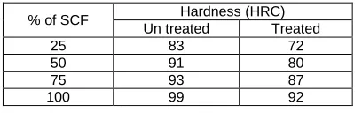
The fibers are cleaned normally in clean running water and dried. A solution is made in a glass beaker with 6% NaOH and 80% of distilled water is added to it. The dried fibres are soaked in the prepared NaOH solution. Soaking is carried out for different time intervals depending upon the strength of fiber required. For this work, the fibers are soaked in the solution for three hours. After the soaking process, the fibers are taken out and washed in running water and dried for another 2 hours. A mould of 60 mm length and 40 mm diameter is created using GI sheet mould. A transparent plastic sheet (OHP Sheet) is taken, releasing agent is applied over it and fitted with the inner side of the mould and then allowed to dry it. A glass beaker and a glass rod or a stirrer are taken and cleaned well with running water and then with warm water. Calculated quantity of vinylester resin is added with measured quantity of promoter/accelerator/catalyst. The mixture is stirred for nearly 15 minutes to create a homogeneous mixture of resin and accelerator. After mixing, calculated quantity of fibers is added and stirring process is continued for the next 45 minutes. After that, measured quantity of catalyst is added and stirred for a short while. Then the mixture is poured into the mould and rammed mildly for uniform settlement. The mould is allowed to solidify for 24 hours. Rule of hybrid mixtures are used to prepare the composites of untreated and treated hybrid composites as shown in the Table 2.The SCF and CF fibers are cut to the required size of 1.5 cm for experimentation. Hardness of treated and untreated for different percentages of SCF in composite is measured on Rockwell hardness testing machine and presented in the Table 1. Both the composites have almost close hardness. The hardness for the both composites has been increased with increase of percentage of SCF.
Table 1. Hardness of untreated and treated composites
% of SCF Hardness (HRC) Un treated Treated
25 83 72
50 91 80
75 93 87
100 99 92
3.
Experimentation
As shown in the Table 2, experimental plan is prepared as per Taguchi orthogonal array of L8 and drilling experiments
were performed on the proposed composites at two levels of cutting speed and feed rates. Experimental set up and workpieces shown in the Figures 1 and 2 respectively.
i. Each experiment was started with a new tungsten carbide drill bit having 12 mm diameter. In each experiment, four holes were made on the work piece. ii. As shown in Figure. work piece was fixed on the
machine table, drill bit was fixed to the spindle. A force dynamometer is held below the table to measure cutting and thrust forces.
iii. A Laser Doppler Vibrometer was placed in front of the machine and produced laser beam. The beam was focused on the drill bit to measure vibration of drill bit during the drilling.
iv. Surface roughness of drilled holes was measured using microsurf.
Figure 1. Schematic representation of the experimental set up and dynamometer vertical machining centre
Figure 2 SCF/carbon composite
4.
Results and Discussions
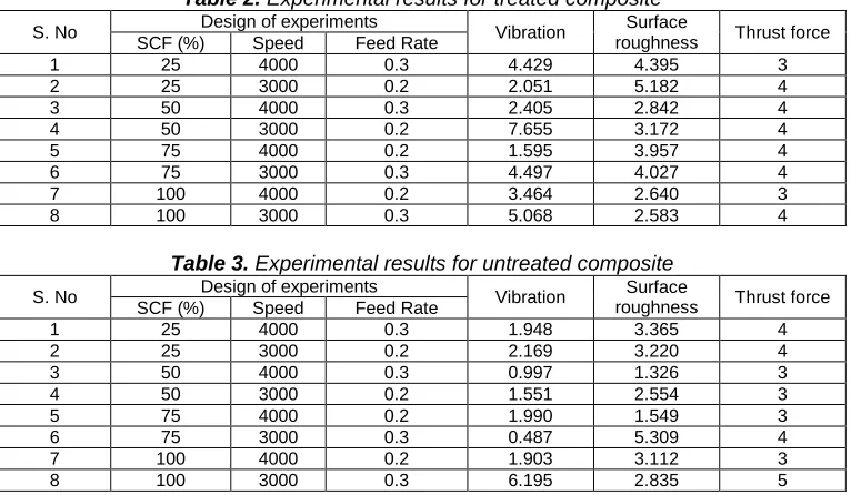
257 Table 2. Experimental results for treated composite
S. No Design of experiments Vibration Surface
roughness Thrust force SCF (%) Speed Feed Rate
1 25 4000 0.3 4.429 4.395 3
2 25 3000 0.2 2.051 5.182 4
3 50 4000 0.3 2.405 2.842 4
4 50 3000 0.2 7.655 3.172 4
5 75 4000 0.2 1.595 3.957 4
6 75 3000 0.3 4.497 4.027 4
7 100 4000 0.2 3.464 2.640 3
8 100 3000 0.3 5.068 2.583 4
Table 3. Experimental results for untreated composite
S. No Design of experiments Vibration Surface
roughness Thrust force SCF (%) Speed Feed Rate
1 25 4000 0.3 1.948 3.365 4
2 25 3000 0.2 2.169 3.220 4
3 50 4000 0.3 0.997 1.326 3
4 50 3000 0.2 1.551 2.554 3
5 75 4000 0.2 1.990 1.549 3
6 75 3000 0.3 0.487 5.309 4
7 100 4000 0.2 1.903 3.112 3
8 100 3000 0.3 6.195 2.835 5
4.1 Interaction effect of parameters on the responses for treated composite
Effect of drilling parameters and percentage of SCF on the surface roughness is shown in the Figure 3. Surface roughness on the drilled hole was found to be reduced as the percentage of SCF is increased in the proposed
composite. Effect of spindle speed and feed rate along with SCF on the surface roughness is very less. But the feed rate and spindle speed have mixed effect on the surface roughness when their interaction is considered as shown in the Figure 3 (c).
Figure 3. Interaction effect of parameters on the Surface roughness
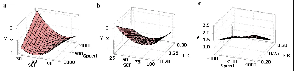
Effect of drilling parameters and percentage of SCF on the amplitude of drill vibration was shown in the Figure 4. The amplitude of drill vibration was found to be high at 100 percentage of SCF at 3000 rpm of spindle and it is less at 25 percentage of SCF and 4000 rpm of spindle speed. From the Figure 4 (b), it was found that the vibration
amplitude is found to be less at 0.2 mm/rev of drill bit for 25% of SCF. From the interaction effect of spindle speed and feed rate, it was observed that the spindle speed has significant effect on the vibration amplitude at 3000 rpm of spindle speed.
Effect of drilling parameters and percentage of SCF on thrust force was shown in the Figure 5. From the Figure 5 (a), the trust force was found to be high at 60% of SCF at 4000 rpm of spindle and it is less at 25 and 100 percentage of SCF for all spindle speeds. From the Figure 5 (b), it was
found that the thrust force is less at 0.2 mm/rev of drill bit for 100% of SCF. From the interaction effect of spindle speed and feed rate, it was observed that the spindle speed has significant effect on the thrust force.
Figure 5. Interaction effect of parameters on the thrust force
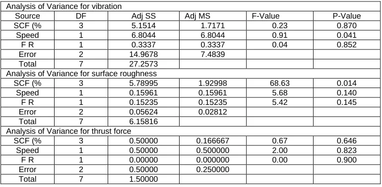
4.2 Analysis of Variance for treated SCF/Carbon fire composite
The experimental results of drill vibration amplitude, surface roughness and thrust force are analysed with ANOVA to identify significant parameters which are affecting the responses. The ANOVA was carried out at 95% of confidence level and presented in the Table 4. The
parameters which are having p-value less than 0.05 are said to be significant. Spindle speed and percentage of SCF are found to be significant on amplitude of drill vibration and surface roughness respectively. But three parameters were not having any significance on the thrust force.
Table 4. Analysis of Variance for responses for treated composite
Analysis of Variance for vibration
Source DF Adj SS Adj MS F-Value P-Value
SCF (% 3 5.1514 1.7171 0.23 0.870
Speed 1 6.8044 6.8044 0.91 0.041
F R 1 0.3337 0.3337 0.04 0.852
Error 2 14.9678 7.4839
Total 7 27.2573
Analysis of Variance for surface roughness
SCF (% 3 5.78995 1.92998 68.63 0.014
Speed 1 0.15961 0.15961 5.68 0.140
F R 1 0.15235 0.15235 5.42 0.145
Error 2 0.05624 0.02812
Total 7 6.15816
Analysis of Variance for thrust force
SCF (% 3 0.50000 0.166667 0.67 0.646
Speed 1 0.50000 0.500000 2.00 0.823
F R 1 0.00000 0.000000 0.00 0.900
Error 2 0.50000 0.250000
Total 7 1.50000
Empirical relations for the three responses in terms of parameters are given below (treated composite):
V = 33.86 + 0.9781 SCF 0.01584 Speed 160.2 F R 0.000228 SCF*SCF - 0.000127 SCF*Speed 1.785 SCF*F R + 0.06978 Speed*F R
(1)
S R = -32.89 - 0.1407 SCF + 0.01198 Speed + 175.7 F R + 0.000160 SCF*SCF + 0.000012 SCF*Speed + 0.06600 SCF*F R - 0.05132 Speed*F R
(2)
FT = 7.000 0.05000 SCF + 0.000500 Speed 25.00 F R
0.000400 SCF*SCF + 0.000000 SCF*Speed
+ 0.4000 SCF*F R + 0.000000 Speed*F R (3)
4.2 Interaction effect of parameters on the responses for un treated composite
259 Figure 6. Interaction effect of parameters on the thrust force
Effect of drilling parameters and percentage of SCF on the surface roughness is shown in the Figure 7. Percentage of SCF has mixed effect on the surface roughness for all speed shown in the Figure 7(a). At 50% SCF, the thrust force is found to be less and at high and low % of SCF, the
thrust force is high. The surface roughness is directly proportional to thrust force at 25 to 75% of SCF (Figure 7.b). The surface roughness is directly proportional to speed at all feed rates shown in Figure 7 (c).
Figure 7 Interaction effect of parameters on the Surface roughness
Effect of drilling parameters and percentage of SCF on amplitude of drill vibration was shown in the Figure 8. Amplitude of drill vibration was found to be reduced as the percentage of SCF is increased in the untreated composite
at 4000 rpm of spindle speed (Figure 8.a). Percentage of SCF has mixed effect on the vibration amplitude. At 50% SCF, the thrust force is found to be less and at high and low % of SCF, the vibration is high (Figure 8.a).
Figure 8. Interaction effect of parameters on the vibration amplitude
4.4 Analysis of Variance for un treated SCF/Carbon fire composite
The experimental results of drill vibration amplitude, surface roughness and thrust force are analysed with ANOVA to identify significant parameters which are affecting the responses. The ANOVA was carried out at 95% of confidence level and presented in the Table 5. The parameters which are having p-value less than 0.05 are
said to be significant. Feed rate and percentage of SCF are found to be significant on amplitude of drill vibration, spindle speed is found to be significant on surface roughness. But three parameters were not having any significance on the thrust force.
Table 5. Analysis of Variance for responses for untreated composite
Analysis of Variance for Vibration
Source DF Adj SS Adj MS F-Value P-Value
SCF (%) 3 0.95061 0.316871 1.42 0.039
Speed 1 0.00051 0.000512 0.00 0.966
F R 1 0.27602 0.276025 1.24 0.032
Error 2 0.44698 0.223489
Total 7 1.67413
Analysis of Variance for surface roughness
SCF (% 3 2.14019 0.71340 0.95 0.551
Speed 1 0.82304 0.82304 1.09 0.046
F R 1 0.02000 0.02000 0.03 0.886
Error 2 1.50862 0.75431
Total 7 4.49186
Analysis of Variance for thrust force
SCF (% 3 1.3750 0.4583 3.67 0.222
Speed 1 1.1250 1.1250 9.00 0.945
F R 1 1.1250 1.1250 9.00 0.945
Error 2 0.2500 0.1250
Total 7 3.8750
Empirical relations for the three responses in terms of parameters are given below (un treated composite):
Vibration = 4.815 0.005870 SCF + 0.004132 Speed 1.025 F R + 0.000538 SCF*SCF - 0.000033 SCF*Speed + 0.1924 SCF*F R - 0.006530 Speed*F R
(4)
S R = -10.21 + 0.01301 SCF + 0.001289 Speed + 109.5 F R + 0.000759 SCF*SCF + 0.000013 SCF*Speed - 0.6820 SCF*F R - 0.01786 Speed*F R
(5)
FT = -8.000 - 0.06500 SCF + 0.004750 Speed + 42.50 F R
+ 0.000600 SCF*SCF - 0.000020 SCF*Speed + 0.2000 SCF*F R - 0.01500 Speed*F R
(6)
5.
Multi response optimization
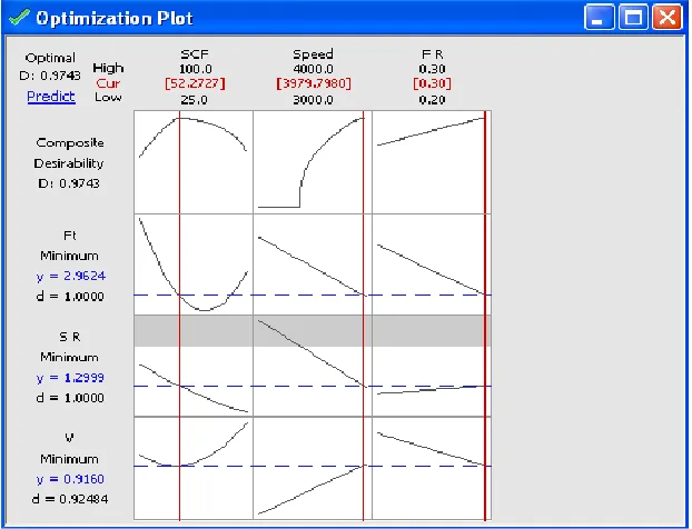
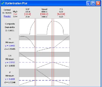
In the present study, a multi response optimization technique was used to optimize process parameters for minimum thrust force, surface roughness and amplitude of drill vibration. In the multi response optimization, a desirability value is determined between 0 and 1 using gradient algorithm. If the desirability value close to 1, then the response is said to be accepted and if the desirability value close to 0, then the response is said to be unaccepted [17]. The multi response function for the treated and untreated composite was shown in the Figure 9 and 10 respectively. Better machining characteristics were found for treated composites at optimum parameters, 52.2727 percent of SCF, 3980 rpm of drill speed and 0.3 mm/rev of feed rate. Similarly, better machining characteristics were found for untreated composites at optimum parameters, 100 percent of SCF, 4000 rpm of drill speed and 0.2030 mm/rev of feed rate
261 Figure 10. Multi response function for three responses of untreated composite
6.
Conclusion
In the present work, SCF/carbon composite was prepared with a commercially available vinylester, methyl ethyl ketone peroxide (catalyst) and cobalt napthenate (accelerator). The prepared composite is aimed to use in aircraft application. Drilling characteristics were studied for both treated and untreated composites. The following characteristics can be drawn from this work:
1. Interaction effect of parameters on the thrust force, surface roughness and amplitude of drill vibration was studied for both the untreated and treated composites. 2. In ANOVA for treated composite, the feed rate and
percentage of SCF are found to be significant on amplitude of drill vibration, spindle speed is found to be significant on surface roughness. But three parameters were not having any significance on the thrust force. 3. In ANOVA for treated composite, the feed rate and
percentage of SCF are found to be significant on amplitude of drill vibration, spindle speed is found to be significant on surface roughness. But three parameters were not having any significance on the thrust force. 4. Better machining characteristics were found for treated
composites at optimum parameters, 52.2727 percent of SCF, 3980 rpm of drill speed and 0.3 mm/rev of feed rate.
5. For untreated composites, better machining characteristics were found at optimum parameters, 100 percent of SCF, 4000 rpm of drill speed and 0.2030 mm/rev of feed rate.
7.
References
[1]. Alper Uysal, 2016 Proc I Mech E Part B: J. Engg. Manu. DOI: 10.1177/0954405416662084
[2]. Rakesh P K, Singh I, and Kumar D, 2012 Proc. I Mech E Part L: J. Mat. Design and Applications DOI: 10.1177/1464420711430007
[3]. Ramesh B, Elayaperumal A, Satishkumar S, Anish Kumar and T Jayakumar,2016 Proc I Mech E Part L: J. Mat. 230(2) 558
[4]. Suleyman Neseli, 2014, Adv. in Mech. Engi. 2014 1
[5]. P Raveendran and P Marimuthu, 2015 Adv. in Mech. Engi. 7(12), 1
[6]. Plastics Vikas Dhawan , Kishore Debnath , Inderdeep Singh and Sehijpal Singh, 2016 Proc I Mech E Part L: J. Mat.: Des. and App. 230(2) 603
[7]. Palanikumar K, 2006 J. of reinf. Plast. and comp. 25,1739
[8]. Mohan N S, Ramachandra, Kulkarni S M, 2005 J. Reinf. Plast. and comp. , 24 1247
[9]. Pramendra Kumar Bajpai , Kishore Debnath and Inderdeep Singh , 2015 J. Thermoplastic Comp. Mat. DOI: 10.1177/0892705715575094
[10].Rajasekaran T, Palanikumar K and Vinayagam BK, 2011 J. Comp. Mat. 46(7) 809
[12]. Erol Kilickap, 2010 J. Comp. Mat. 45(6) 727
[13]. Krishnamoorthy A and Rajendra Boopathy S, Palanikumar K, 2009 J. Comp. Mate. 43 2885
[14]. Paulo Davim J, Francisco Mata,V, Gaitonde N, Karnik S. R, 2010 J. of Thermoplastic Comp. Mat. 23 5
[15]. Sarma P M M S, Karunamoorthy L, palanikumar K, 2008 J. Reinforced Plast. and Comp. 27 711
[16]. Prakash S and Palanikumar K, 2010, J. Comp. Mat. 45(16 1639