IJEDR1701050
International Journal of Engineering Development and Research (www.ijedr.org)1
Developing a Heuristic Model To Solve Cell
Formation Problem In Cellular Manufacturing
1
Gagan Pansare ,
2Dr. Archana Nema
1Rerearch Scholar, Mechanical Department, Bansal institute of Science &Technology, Bhopal, India 2Professor, Mechanical Department, Bansal institute of Science &Technology, Bhopal, India
________________________________________________________________________________________________________ Abstract - In this work a new Heuristic Model has been developed to solve Cell Formation Problem in Cellular manufacturing. A mathematical model has been developed to count actual intercellular movements. Operation Sequence & Production Volume taken as a criterion for forming the cell. A performance measure is used after some modification on existing method of Nair & Narendran model (1998).The work is going to generate an algorithm for optimal number of Cells calculation. The number of machines & number of parts are taken as criteria for the calculation of number of Cells to be form for given production plan. Between an upper and lower limit on number of Cells Form is use to restrict the unwanted cell configuration and increase the efficiency of Model. The Best Cell configuration select on the bases of minimum Intercellular Movement which also turn cut the Material Handling cost. So for all size (small medium & large) problems, proposed Model can be use to get the real number of inter-cell movement and number of cells calculation on the bases of given Production plan
Index Terms- Cellular manufacturing system, cell formation, Grouping efficiency, Group technology, inter-cellular movement, Part machine Incidence Matrix, production Volume. (Keywords)- CMS, CF, GE, GT, ICM, PMIM, PV
________________________________________________________________________________________________________
I.INTRODUCTION
Cellular Manufacturing is an application of Group Technology has been recognized as one of the most recent technological innovation in batch type production. Cellular Manufacturing is a tool to gain economic advantage of similar product .CM is an approach that helps to build variety of product with minimum wastage of resources. The primary difference between Cellular Manufacturing and other manufacturing methods is that Cellular Manufacturing is focused on one piece flow design instead of on making multiple parts and sending them to the next machine/process, as in batch production. The determined is to minimize waste and maximize value added productivity. Cellular Manufacturing is based on the concept of process balancing, which results in continuous product flow, reduced inventory, increased production, reduced wait time between operations, and minimized part movement. One of the most important problem faced in practice of Cellular Manufacturing is grouping of parts and machines into families called Cell Formation.
Cell Formation ideas were first systematically presented by Burbidge (1963)[5] following the pioneering work of Mitrofanov (1959)[13]. The literature on Cell Formation can be broadly classified in two ways – one based on techniques used for Cell Formation and other one the way the Cell Formation problem is modeled. Crama and Oosten (1996)[6] made a study on various models for Cell Formation problems
II. LITRATUREREVIEW
Cell Formation using Heuristics-"Heuristics stand for strategies using readily accessible though loosely applicable information to control problem-solving processes in human beings and machines."(Pearl 1984)[17]Heuristics, in more popular understanding, are rules of thumb, educated guesses, intuitive judgments or simply common sense ideas to solve a particular problem. A heuristic improves the efficiency of a search process, possibly by sacrificing claims of completeness (Rich and Knight 1991)[19].Heuristic algorithms are used to provide quick approximate solutions to hard combinatorial optimization problems. A heuristic algorithm is called an approximate algorithm where the performance of the heuristic is assessed in terms of worst and average case behavior. They do not guarantee optimal solutions. Similarly, close neighbor algorithm by Boe and Cheng (1991)[3]. GRAFICS by Srinivasan and Narendran (1991)[22], CASE by Nair & Narendran (1998)[14], ACCORD by Nair & Narendran (1999)[15] are some well-known heuristics for solving CF problem found in the literature.
Cell Formation using Mathematical Programming Techniques -A number of research studies for cell formation using mathematical programming approach appeared in literature. They are classified under integer programming (Kusiak 1987[11], Co and Araar 1988[7]), dynamic programming (Ballakur and Steudel 1987) [1], goal programming (Shafer and Rogers, 1993a)[21], and linear programming (Boctor 1991)[4].
Operation Sequence based approaches- Most CF methods use binary machine part/matrix and do not have operation sequence information. The approaches reviewed under this section further have operation sequence as part of the input data. Sofianopoulou (1997)[23] presented a CF method formulated as a linear integer program. It tries to minimize the inter-cellular flow between cells. This method does not pre-specify the number of cells to be formed.
IJEDR1701050
International Journal of Engineering Development and Research (www.ijedr.org)324
and within cell material flows using similarity co-efficient approach to cluster parts and machines. But, this approach failed to take into account the issues of number of cells and duplication. Won & Lee (2001)[27] also considered the production volume factor in his formulation but the model was failed due to erroneous intercellular count.III. PROBLEM IDENTIFICATION
Most of previous researches that addressed Cell Formation technique were focused on methodologies where grouping of machines/resources were done based on similarity, and operation sequence. Also in the previous researches none have addressed the number of cells to be formed for given a set of information like number of machines, number of parts, operation sequence and production volume. Nair & Narendran (1998)[14] used most of the above factors for the formation of cells. But the solution he obtained lacked optimality for formation of cells. New method of Cell Formation eliminate these all problem & provides an optimal solution with efficient grouping and count actual number of intercellular movement along with a performance measure for the cells being formed. The new method also includes an algorithm for number of cells calculation.
NOTATIONS USED IN MODEL
n number of parts m number of machines pmin minimum number of cells pmax maximum number of cells r index of part type, r = 1,……..n i, j index of machine type, 1,……m k index of cells (families), k = 1,……p
Lf lower limit of part family size assign to 1 cell Uf upper limit of part family size assign to 1 cell Lc lower limit of machines inside 1 cell
Uc upper limit of machines inside 1 cell
nr Total number of operation required by part 'r' dr Production volume of part 'r'
TOTOPk Total number of operations in the kth cell
NOPk Total number of non-operations(voids) in the kth cell
IV.ALGORITHM
Step 1: Start the Process
Step 2: Input the number of machines, m Step 3: Input the number of parts, n
Step 4:If number of machines, m ≤ 24, and then Lcmin = 2, Lcmax = no.of machines Lcmin
Go to Step 6 Else Go to Step 5
(Here the algorithm makes sure that the maximum Number of machines that can be allotted is 12) Step 5: Calculate Lc min = (no.of machines
12 ), Lcmax =
no.of machines Lcmin
Step 6:If number of parts, n ≤ 24 and then Lf min = 2, Lfmax = no.of parts Lfmin
Go to Step 8 Else Go to Step 7
(Here the algorithm makes sure that the maximum Number of parts that can be allotted is 12) Step 7: Calculate Lf min = (no.of parts
12 ), Lfmax =
no.of parts Lfmin
IJEDR1701050
International Journal of Engineering Development and Research (www.ijedr.org)325
Step 11: Set Lc= Lc min and Uc= 12Step 12: Group the machines using New CF Method
Step 13: Calculate Intercellular flow count and Bond Efficiency Step 14: Display the result
Step 15: If Pmin= Pmax, Go to Step 18 Else Go to Step 16 Step 16: Set Pmin= Pmin+ 1
Step 17: Go to step 9 Step 18: Stop the process
V.MATHEMATICALMODEL
To begin with, PMIM representing the operation sequences and production volumes for grouping of machines into cells and components into part families are given. The inter-cell flows or the sum of the exceptional elements are minimized using a mathematical model. The formulation of the model is shown below
ICM=Min∑𝒑𝒑𝒎𝒎𝒊𝒊𝒏𝒏𝒊𝒊=𝟏𝟏 ∑𝒏𝒏𝒓𝒓=𝟏𝟏∑𝒎𝒎𝒊𝒊=𝟏𝟏∑ �𝒅𝒅𝒎𝒎𝒊𝒊≠𝟏𝟏 𝒓𝒓∗ 𝒃𝒃𝒊𝒊𝒊𝒊𝒓𝒓∗ 𝑿𝑿𝒊𝒊𝒊𝒊𝒓𝒓𝒊𝒊�𝟏𝟏/𝟐𝟐 Eq. 3.1
Where,
bjir=� 1 if volume of material flows from machine ′i′to machine′j′of part ′r′ 0 otherwise
xirk= �1 if machine′i′of part′r′belongs to cell k 0 otherwise
xjrk= �1 if machine′j′of part′r′belongs to cell k 0 otherwise
Xijrk= | xirk-xjrk| Eq. 3.2 ∑𝑝𝑝𝑟𝑟=1𝑥𝑥𝑟𝑟𝑟𝑟= 1, r = 1 ...n. Eq. 3.3
xrk= �1 if part′r
′blongs to cell k 0 otherwise
Lf < ∑𝑛𝑛𝑟𝑟=1𝑥𝑥𝑟𝑟𝑟𝑟≤ 𝑈𝑈𝑓𝑓, k = 1 ...p. Eq. 3.4
∑𝑝𝑝𝑟𝑟=𝑙𝑙𝑦𝑦𝑖𝑖𝑟𝑟= 1, i= 1 ...m. Eq. 3.5
yik= �1 if machine′j
′ blongs to cell k 0 otherwise
Lc <∑𝑚𝑚𝑖𝑖=1𝑦𝑦𝑖𝑖𝑟𝑟 ≤Uc, k = 1 ...p. Eq. 3.6
Eq.3.1 minimizes the intercellular movement for any part machine configuration. Eq.3.2 checks whether there exists any intercellular movement between machines for each product. Constraint sets Eq.3.3 and Eq.3.5 are to ensure that a part and a machine can be assigned to only one cell. Constraint sets Eq.3.4 and Eq.3.6 are to restrict the number of parts and machines that can be allotted to a cell.
IJEDR1701050
International Journal of Engineering Development and Research (www.ijedr.org)326
algorithm is run for different part/machine configurations with 2 cluster configuration being the least configuration. The proposed model is used to calculate both the minimum and maximum number of cells to be formed, based on the number of machines and parts given as input. The algorithm as is follows.VI.PERFORMANCE MEASURES
Compactness-Compactness of each cell is defined as the ratio of the number of operations within it to the maximum number of operations possible in it.
Compactness = ∑Pmink=1 TOTOPk ∑Pmink=1 (TOTOPk+NOPk)
CF Efficiency-Cell Formation efficiency is defined as the ratio of the difference between the maximum number of inter-cell travels possible and the number of inter-cell travels actually required by the system to the maximum number of inter-cell travels possible.
CF efficiency = X−Y X Where,
X=The maximum number of inter-cell travels possible
Y=The number of inter-cell travels actually required by the system.
There exists a trade-off between intercellular movement and compactness of cells formed. With an increase in the number of cells, there is a chance of getting high compactness but the number of intercellular movement also increases. So both values are selected in such a way that an optimal solution is obtained without suppressing both of them.
Bond Efficiency– (β) = (CF efficiency +Compactness)/ 2
The new method of Bond efficiency which minimizes intercellular flow and maximizes the density of 1’s is used for determining
the cell configuration. Bond Efficiency (β), equation 3.7 is defined as a weighted average of Compactness& CF efficiency.
BOND EFFICIENCY={X−Y X +
∑PK=1TOTOPK
∑PK=1(TOTOPK+NOPK)}/2 EQ. 3.7
CF efficiency = X−Y
X Eq.3.8
Where,
X= ∑nr=1dr(nr−1)
Y = ∑nr=1∑n1r−1Xijrdr
Compactness = ∑ TOTOPk
p k=1
∑pk=1(TOTOPk+NOPk)
Eq.3.9
For a perfect diagonal block, Compactness takes the value of ‘1; and NOPk takes the value ‘0’.
VII. METHODOLOGY
Analysis (7 Machines & 4 Parts)
MACHINE
IJEDR1701050
International Journal of Engineering Development and Research (www.ijedr.org)327
A R T
A 1 2 3 4 800
B 3 2 1 4 200
C 2 1 3 4 250
D 1 2 3 4 1000
Table3.6 Part Machine Matrix with sequence and production volume The step-by-step procedure for the above case study is detailed below, from the algorithm (3.2.4.)
Number of machines, m = 7 Number of parts, n = 4
Since number of machines, m≤24, then Lc min = 2
Lcmax = no.of machines Lcmin
= (7/2) =3.5 = 3(rounding off to lower integer value) i.e. Lc max = 3
Since number of parts, n ≤ 24, Lf min = 2, Lfmax = no.of parts
Lfmin
= (4/2) i.e. Lf max = 2
Minimum cells required, pmin= Max (Lc min, Lf min)
= Max (2, 2) pmin= 2
Maximum cells required,
pmax= Min (Lc max, Lf max)
= Min (3, 2)
pmax = 2 (maximum no. of cell required)
Setting Lf = Lf min & Uf = 12, but in this case Uf = 4, But the sequence information is captured using the below formula,
bjir=� 1 if volume of material flows from machine ′i′to machine′j′of part ′r′ 0 otherwise
dr = production volume of part ‘r’
Machine From –To
IJEDR1701050
International Journal of Engineering Development and Research (www.ijedr.org)328
The volume of material flowing between different machines for parts A, B, C and D are shown in Table 3.7.Table 3.7 From –To chart for all Parts Calculation of Intercellular Moves based on New Model
Table 3.7 is taken as input for the formation of cells, by minimizing the intercellular movement as the criterion for Cell Formation, using Eq.3.1. After inputting the values, Eq.3.1 becomes,
2 4 7 7
Min
∑
∑
∑ ∑
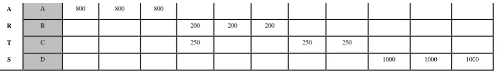
(dr*bijr*xijrk)/2 k=1 r=1 i=1 j≠1The cell configuration obtained after using the above formula for Cell Formation is detailed in Table 3.8.
Table 3.8.Part- Machine Matrix The intercellular movement is calculated by,
(d1b121X1211 + d1b121X1212 + d1b231X2311 + d1b231X2312 + d1b341X3411 + d1b341X3412 + d2b432X4321 + d2b432X4322 + d2b322X3221 + d2b322X3222+ d2b262X2621 + d2b262X2622 + d3b433X4331 + d3b433X4332 + d3b363X3631 + d3b363X3632 + d3b673X6731 + d3b673X6732+ d4b454X4541 + d4b454X4542+ d4b564X5641 + d4b564X5642 + d4b674X6741 + d4b674X6742) / 2
= ((800*1*0) + (800*1*0) + (800*1*0) + (800*1*0) + (800*1*1) + (800*1*1) + (200*1*1) + (200*1*1) + (200*1*0) + (200*1*0) + (200*1*1) + (200*1*1) + (250*1*0) + (250*1*0) + (250*1*0) + (250*1*0) + (250*1*0) + (250*1*0) +(1000*1*0) + (1000*1*0) + (1000*1*0) + (1000*1*0) + (1000*1*0) + (1000*1*0)) / 2,
Total inter-cellular count= 1200
PERFORMANCE MEASURES-
In order to evaluate the performance of the cells formed measures like Compactness and Bond efficiency are used from the proposed algorithm
CF efficiency =𝑋𝑋−𝑌𝑌 𝑋𝑋 Where,
X= ∑𝑛𝑛𝑟𝑟=1𝑑𝑑𝑟𝑟(𝑛𝑛𝑟𝑟−1) = ∑4𝑟𝑟=1𝑑𝑑𝑟𝑟(𝑛𝑛𝑟𝑟−1)
= ((800*3) + (200*3) + (250*3) + (1000*3)) X= 6750
And Y= ∑𝑛𝑛𝑟𝑟=1∑𝑛𝑛1𝑟𝑟−1𝑋𝑋𝑖𝑖𝑖𝑖𝑟𝑟𝑑𝑑𝑟𝑟 = ∑4𝑟𝑟=1∑4−11 𝑋𝑋𝑖𝑖𝑖𝑖𝑟𝑟𝑑𝑑𝑟𝑟 = (1*800) + (2*200)
A A 800 800 800
R B 200 200 200
T C 250 250 250
S D 1000 1000 1000
MACHINE
P A R T
1 2 3 4 5 6 7
A 800 800 800 800
B 200 200 200 200
C 250 250 250 25O
IJEDR1701050
International Journal of Engineering Development and Research (www.ijedr.org)329
Y=1200CF efficiency = 6750−1200
6750 = 0.8223
Compactness = ∑𝑃𝑃𝑃𝑃𝑃𝑃𝑃𝑃𝑘𝑘=1 𝑇𝑇𝑇𝑇𝑇𝑇𝑇𝑇𝑃𝑃𝑘𝑘 ∑𝑃𝑃𝑃𝑃𝑃𝑃𝑃𝑃𝑘𝑘=1 (𝑇𝑇𝑇𝑇𝑇𝑇𝑇𝑇𝑃𝑃𝑘𝑘+𝑁𝑁𝑇𝑇𝑃𝑃𝑘𝑘)
= (3+8)
(3+8)+(1+2) = 0.7857 Bond Efficiency (β)
(β) = (CF efficiency +Compactness)/ 2
= {X−Y X +
∑pk=1TOTOPk
∑pk=1(TOTOPk+NOPk)
}/2
= (0.8222+0.7857)/2 β = 0.8040
Since the maximum number of cells (pmax) possible for the above case is only 2, the algorithm is stopped at this point. Otherwise the algorithm is run until the maximum valve of cell configuration is reached and the results are calculated in the same manner for all cell configurations
VII. Conclusion
In this work, a systematic Heuristic Model has been developed For Cell Formation in Cellular Manufacturing for all (small-medium and large) size problems. A mathematical model has been developed to count actual intercellular movement. The developed model includes details like Production volume and Operation sequence for Cell Formation. The performance measure is used to test the cells efficiency which being formed after few modifications in the existing method from Nair & Narendran (1998). In order to check the entire methodology three different problems small, medium and large size were used. An algorithm is generated to calculate the optimal number of cells on the bases of given input like number of machine and number of parts. Upper and lower limit of number of cells used to eliminate unwanted configuration of cells. The methodology is run for different part/machine configurations with 2 cell configuration being the least configuration for when of small problem (machines or parts limited to 24). In case of medium& large size problem (more than 24 machines and parts) the least cell configuration is calculated using a small algorithm and the configuration is set based on the obtained value. The model is also used to calculate the most allowable cell configuration for any given production plan. Limitations are also placed on the number of machines and parts that can be assigned to a cell.
References
[1] Ballakur, A. and Steudel, H.J., 1987. A with-in cell utilization based heuristic for designing cellular manufacturing systems. International Journal of Production Research, 25 (5), 639-655.
[2] Beaulieu, A. Gharbi, A. And Ait-Kadi., 1997.An algorithm for the cell formation and the machine selection problems in the design of a cellular manufacturing system.International Journal of Production Research, 35 (7), pp.1857-1874.
[3] Boe, W.J. and Cheng, C.H., 1991.A close neighbour algorithm for designing cellular manufacturing systems. International Journal of Production Research,29(10), 2097-2116.
[4] Boctor, F.F., 1991.A linear formulation of the machine-part cell formation problem.International Journal of Production Research, 29 (2), pp.343-356.
[5] Burbidge, J.L. (1963) Production flow analysis. Production Engineer, 42, 742.
[6] Crama, Y. and Oosten, M., 1996.Models for machine part grouping in cellular manufacturing.International Journal of Production Research, 34(6), pp.1693-1713.
[7] Co, H.C. &Araar, A., 1988, “Configuring cellular manufacturing system” International Journal of Production Research, 26(9),1511-1522.
[8] Dimopoulos, C and Mort, N. 2001. A hierarchical clustering methodology basedon genetic programming for the solution of simple cell-formation problems,International Journal of Production Research, 39(1), 1-19.
[9] Gupta, T., 1991.Clustering algorithms for the design of a cellular manufacturing system – an analysis of their performance. Computers and Industrial Engineering, 20 (4), pp.461-468.
[10]Kandiller, L., 1994, A Comparative study of cell formation in cellular manufacturing system. International Journal of Production Research, 32, pp.2395-2429
IJEDR1701050
International Journal of Engineering Development and Research (www.ijedr.org)330
[12] Miltenburg, J. and Zhang.W., 1991. A comparative evaluation of nine well known algorithms for solving the cell formation problem in group technology.Journal of Operations Management, 10 (1), pp.44 -72.[13] Mitrofanov, S.P., 1959.Russian Text; also 1966 Scientific Principles of Group Technology. Part I, Boston: National Lending Library of Science and Technology.
[14] Nair, G.J. and Narendran, T.T., 1998. CASE: A clustering algorithm for cell formation with sequence data. International Journal of Production Research, 36(1), pp157-179.
[15] Nair G.J and Narendran T.T., 1999. ACCORD: a bicriterion algorithm for cell formation using ordinal and ratio level data. International Journal of ProductionResearch, 37(3),pp.539–556
[16] Panneerselvam, R. and Balasubramanian, K.N., 1985. Algorithm grouping of operations sequences. Engineering costs and production economics, 9, pp.125-135
[17] Pearl, J, (1984) Heuristics: intelligent search strategies for computer problem solving,Addison-Wesley, Reading, MA [18] Ramabhatta,V. and Nagi,R., 1998.An Integrated formulation of manufacturing cell formation with capacity planning and multiple routings. Annals of Operations Research, 77, pp.79-95.
[19] Rich, E, and Knight, K, (1991) Artificial Intelligence, McGraw-Hill, New York.
[20] Sarker, Kun Li, (1997). Simultaneous route selection and cell formation: a mixed integer programming time-cost model. Integrated Manufacturing Systems, Volume: 8 Issue: 6 Page: 374 – 377.
[21] Shafer, S.M. and Rogers, D.F., 1993a, Similarity and distance measures for cellular manufacturing, International Journal of Production Research, 31 (5),1131-1142.
[22] Srinivasan, G. & Narendran, T.T. (1991) GRAPHICS - Loss of Pooling Synergy in Cellular Manufacturing Systems. Management Science, 40(4), 466-483.
[23] Sofianopoulou, S., 1999. Manufacturing cells design with alternative process plans and / or replicate machines. International Journal of Production Research, 37(3), pp.707-720.
[24] Vakharia, A.J. and Wemmerlov, U., 1990. Designing a Cellular manufacturing system a material flow approach based on the operation sequences. IIE Transactions, 22 (1), pp.84-97.
[25] Vannelli and Kumar, K.R.,1986.A method for finding minimal bottle-neck cells for grouping part machine families. International Journal of Production Research, 24 (2), pp.387-400.
[26] Waghodekar, P.H. and Sahu, S., 1984.Machine-component cell formation in group technology.MACE.International Journal of Production Research, 22 (6), pp.937-948.
[27] Wemmerlov and Hyer.1987. Research issues in cellular manufacturing, International Journal of Production Research, 25, 413–431