IJEDR1701096
International Journal of Engineering Development and Research (www.ijedr.org)621
Rretrofitting process optimization in CNC machines
using PLC and labview
1
Balaji A,
2Jahir Hussain H,
3Faheem Ashkar M R
1Assistant Professor, 2 UG Scholar, 3 UG Scholar 1Department of Mechatronics Engineering, 1 Kongu Engineering College, Erode, Tamilnadu, India
________________________________________________________________________________________________________ Abstract— This paper inculcates a novel method to control the 3-axis machine with Computer Numerical Control (CNC) codes using LabVIEW and Programmable Logic Controllers (PLC). LabVIEW is used for virtual user interface and PLC is used for machine control. Without burdening the CNC programmer, the paper provides an alternate way to control the CNC machine with minimum cost in comparing with the conventional method. The programmer can use any of the CAD/CAM software to generate the CNC codes. The generated CNC codes are browsed to LabVIEW by means of virtual user interface. The inbuilt program in the LabVIEW can sense any of the CNC codes. After sensing, the codes are being processed in the software to find the co-ordinates of the tool path. The extracted tool path co-ordinates are sent to PLC programming software, RS Logix 500 through OPC server. The inbuilt program in the RS Logix 500 can get the co-ordinates and move the tool accordingly. The overall method is programmed for incremental mode of CNC, so that there is no need of getting positional feedback from the machine. Hence, without having knowledge in the field of LabVIEW programming and PLC logics, the CNC operator can treat the machine similar to the conventional machine.
Index Terms— CNC, LabVIEW, PLC, Relays.
________________________________________________________________________________________________________ I. INTRODUCTION
Manufacturing processes were begun in ancient days itself. The origin of manufacturing machine dates around 1300 BC when the ancient Egyptians first developed the man powered lathe machine. In 18th century, horse powered machines were developed in the American Revolutionary war. Between the late 19th and mid-20th centuries, motors were attached to the machine to semi-automate the manufacturing process. In 1950’s Computer Numerical Control (CNC) machines are developed to computerize the manufacturing process. In CNC machines, end-to-end component design is highly automated using computer-aided design (CAD) and computer-aided manufacturing (CAM) programs. The programs produce a computer file that is interpreted to extract the commands needed to operate a particular machine via a postprocessor, and then loaded into the CNC machines for production. Most of the industries use CNC machines because of its high production rate and high level of accuracy. Hence, it offers high quality products. But CNC machines are more expensive compared to the conventional machines. Hence, there is a need to minimize the cost of the CNC machine by reducing the cost of its physical structure or control module. This paper deals with the minimization of the cost of CNC machines by eliminating the conventional CNC control module with an alternate method of control.
II. METHODOLOGY
Retrofitting is the process of converting normal machine into CNC machines and magnetic punched tapes in the machines are used to read the CNC codes. Even though the CNC machines are versatile, the Geometrical Codes (G codes) are differing from manufactures to manufactures. Each manufacture was pushing its own G codes for defining the tool path. To rectify this problem, the paper completely eliminates the use of magnetic punched tape and uses the existing computer and Programmable Logic Controllers (PLC) in the CNC machines. LabVIEW software is programmed with all the possible CNC codes and while exporting CNC codes in to the LabVIEW, it will extract all the co-ordinates for the tool path and send the values to the PLC simulator, RS Logix 500 through Object Linking and Embedding for Process Control (OPC) server. The PLC program co-ordinates the tool movement accordingly.The machine, which is going to be controlled by CNC codes, consists of 3 axes where the third axis is fixed. Two DC motors are used to control the X and Y axis. Lead screws are used to convert rotational motion into linear motion. Relay circuit is used to convert the 24V output from PLC into 12V to drive the DC motors.
III. DESCRIPTIONOFTHESETUP
IJEDR1701096
International Journal of Engineering Development and Research (www.ijedr.org)622
Power is given by,P = 2 * 3.14 * N * T / 60 T = P * 60 / 2 * 3.14 * N T = 8 * 60 / 2 * 3.14 * 300 T = 0.25 N / m or 2.5 Kgcm Hence, the motor torque is enough to drive load and lead screw.
Figure 1 Assembly view of the setup
IV. MICROLOGIX1000PLC
The MicroLogix 1000 programmable controller as shown in figure. 2 is a packaged controller containing a power supply, input circuits, output circuits, and a processor. The controller is available in 10 I/O, 16 I/O and 32 I/O configurations, as well as an analog version with 20 discrete I/O and 5 analog I/O. Connect the MicroLogix 1000 programmable controller to the personal computer using a serial cable from the personal computer’s serial port to the micro controller. It is also possible to use modems to connect a personal computer to one MicroLogix 1000 controller (using DF1 full-duplex protocol) or to multiple controllers (using DF1 half-duplex protocol). The controller consists of a built-in power supply, central processing unit (CPU), inputs, which you wire to input devices (such as pushbuttons, proximity sensors, limit switches), and outputs, which you wire to output devices (such as motor starters, solid-state relays, and indicator lights). The MicroLogix 1000 programmable controller uses two devices for storing processor files: RAM and EEPROM. The RAM provides easy access storage (i.e., its data is lost on a power down), while the EEPROM provides long-term storage (i.e., its data is not lost on a power down). When the processor file is downloaded to the micro controller, it is first stored in the volatile RAM. It is then transferred to the non-volatile EEPROM, where it is stored as both backup data and retentive data. When a power down occurs, only the retentive data is transferred from the RAM to the EEPROM. (The program files do not need to be saved to the EEPROM since they cannot be modified during normal operation.) If for some reason power is lost before all of the retentive data is saved to the EEPROM, the retentive data is lost. This may occur due to an unexpected reset or a hardware problem. Any MicroLogix 1000 DC input can be configured as sinking or sourcing depending on how the DC COM terminal is wired.
V RELAYS
IJEDR1701096
International Journal of Engineering Development and Research (www.ijedr.org)623
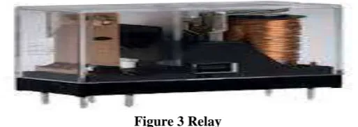
A relay as shown in the figure 3 is an electrically operated switch. Many relays use an electromagnet to operate a switching mechanism mechanically, but other operating principles are also used. Relays are used where it is necessary to control a circuit by a low-power signal (with complete electrical isolation between control and controlled circuits), or where several circuits must be controlled by one signal. The selected components and their speciation’s are listed in table 1 and table 2.Table 1 Components of Electrical setup
S.No Components Specifications
1. PLC
Allen Bradley MicroLogix 1000; Inputs: 10;Outputs: 6;Timers: 40;Counters: 32Communication Port: RS-232
Cable
2. RELAY 24V DC; 16.7 mA
3. LabVIEW National Instruments(students version)
4. Software RS Logix 500
Table 2 Components of mechanical setup
S.No Components Size Quantity Materials
1. Machine Setup
Length= 600mm Breadth= 450mm
Height= 300mm 1 Mild Steel
2. X-axis Lead Screw
Length= 600mm Diameter=20mm
Pitch=2mm 1 Harden Steel
3. Y-axis Lead Screw
Length= 450mm Diameter=20mm
Pitch= 2mm 1 Harden Steel
4. Shaft Mountings
Size= 100mm Diameter=30mm
Bearing= Roller 4 Mild steel
5. DC Motors
Voltage = 12V
Overall Length= 60mm
Diameter=40mm 2
Stainless Steel (Motor Shaft)
VI WORKING
IJEDR1701096
International Journal of Engineering Development and Research (www.ijedr.org)624
Figure 4 LabVIEW user interfaceVII MACHINE CONTROL WITH CNC CODES
G codes are usually followed by X and Y co-ordinates. The co-ordinates are the numerical values which are sent to the PLC’s timer in the RS Logix 500 from LabVIEW. The timer will create a delay. During that delay, the X and Y motor will run. When the timer is stopped, the done bit is enabling and stops the respective motors. Here, the motor having the linear relationship between the time and distance. For example, if the motor runs for 5 seconds, it will move 5cm.
M Codes are the Machine control codes. Hence if it is sensed in the program, PLC ON/OFF the particular device like coolant motor, spindle motor, etc.
Spindle speed is given by Capital ‘S’ letter followed by numerical value. E.g. S250 If capital ‘S’ letter is sensed in the program, the remaining Value 250 is send to Analog PLC’s like Allen Badley Micrologix 1400. The Value 250 is sent to SCP (Scale with Parameter) of the PLC which converts the 250 into equivalent binary digits. According to the values, supply voltage to the spindle motor may vary and the motor runs with 250rpm.
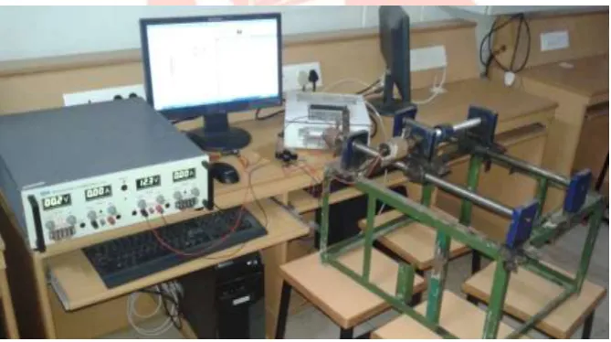
Figure 5 Photograph of setup
VIII CONCLUSION
Thus, the paper provides an alternative way of controlling the CNC machine. The CNC operator needs not to know the PLC ladder logic programming and LabVIEW programming. Because all the CNC codes are programmed in both the software’s. The work grooms the process of retrofitting by completely eliminating the use of magnetic punched tape. It may also use inbuilt PLC’s and computer in the CNC machine. This may further reduce the cost of machine. The work can be further extended by interfacing the computer with the proposed facility to the conventional machine which may be a milling or lathe to convert it to a CNC machine. Spindle speed control and contour milling process are done with the same methodology by using Analog PLC’s. REFERENCES
[1] Allen Badley Micrologix 1000 User manual from Rockwell Automation, India.
[2] David C. Planchard & Marie P. Planchard, Engineering Design with Solidworks 2012, 1st Edition, SDC Publications.
[3] Frank D. Petruzella ‘Programmable Logic Controllers’, 3nd Edition, Tata McGraw Edition.