https://doi.org/10.1007/s10086-018-1774-0
ORIGINAL ARTICLE
Experimental and numerical analyses on nonlinear behaviour
of wooden parallel chord trusses composed of self-tapping screws
Kohei Komatsu1,2 · Qicheng Teng1 · Zherui Li1,2 · Xiaolan Zhang1,2 · Weizhen Cai1 · Zeli Que1
Received: 5 July 2018 / Accepted: 22 October 2018 / Published online: 15 November 2018 © The Japan Wood Research Society 2018
Abstract
Five different wooden parallel chord trusses were made of Canadian spruce 2 by 4 lumbers. Chord–web nodal points were composed of self-tapping-screws (STS) whose numbers per nodal point and allocations in nodal point were considered as the main experimental parameters which were varied from 2rows-2lines till 2rows-4lines. Load–slip relationships at nodal point were evaluated using the joint specimens made of similar materials. These parallel chord trusses were modeled using a finite element method (FEM) program by taking not only nonlinearity of nodal point joints but also material nonlinearity of chord members using fiber model into consideration. Strength properties of the chord members were deduced via specific gravity of chord member based on the regression equations given by a literature. Static monotonic central point loading tests were conducted on five specimens to investigate nonlinear behaviors of wooden parallel chord trusses. Comparisons between observed results by experiments and computed ones by FEM calculations showed a tendency that material nonlinearity gave less effect on the total nonlinear behaviour of the specimens when joint performance was inferior, on the other hand, as the joint performance increased material nonlinearity gave dominant effect on the total nonlinear behaviour of the specimens.
Keywords Wooden parallel chord truss · Self-tapping screw · Finite element method
Introduction
Self-tapping screw (STS) has higher strength and stiffness compared with traditional screw as it is made of stronger steel, hardened threads [1, 2] and a little bit larger ratio of nominal thread and shank diameter [2]. Due to this excel-lent performance, STS obtained higher status and broader reputation in various countries as a new-era’s multi-purposes fastener.
One of the representative uses of STS is for high-per-formance tensile splice timber joints. In this aspect, in 2001, Blass and Bejtka [1] first clarified experimentally that the wood-to-wood tensile single shear joint composed of inclined STS with angle of 60° between screw axis and loading direction showed 1.5 times load-carrying capacity
of that of traditional 90° tensile single shear joint. In 2002, they further proposed theoretical equations [3] for predicting load carrying capacity of the inclined STS joint by taking the effect of yielding and embedment of screw into consid-erations based on Johansen theory [4]. In the same year, Kevarinmäki [5] proposed design equations for withdrawal strength and stiffness of wood-to-wood as well as LVL-to-LVL inclined STS tensile single shear or/and X-shear (both tensile and compressive) joint without considering the effect of yielding and embedment of screw based on the existing European standard [6]. In 2006, Tomasi et al. [7] presented experimental and numerical results of the static, as well as push–pull cyclic loading test on wood-to-wood inclined STS X-shear joint including traditional 90° shear joints for clarifying ductility of STS timber joints. In Chile, Opazo and Bustos [8] confirmed applicability of Bejtka and Blass model [3] to the inclined STS tensile single shear joints made of Chile-grown radiate pine. After these pioneering researches, a lot of researches for making sure the maximum load carrying capacity [2, 9–17] as well as stiffness [12–17] of inclined STS wood-to-wood shear joint as well as steel-to-wood joint [9, 11] have been carried out until today.
* Zeli Que
1 Department of Timber Structures, College of Material
Science and Engineering, Nanjing Forestry University, No. 159 Lonpan Road, Nanjing 210037, Jiangsu Province, China
2 Research Institute for Sustainable Humanosphere, Kyoto
Next important role of STS might be for reinforc-ing inferior strength properties of timber. In this aspect, various researches have also been reported up to recently [18–24].
Among various usages of STS mentioned above, in this article, we paid our attention to mainly the withdrawal performance of STS and aimed to make a wooden paral-lel chord truss specimen whose mechanical performance is controlled in some extents by changing the number of STS to be used for connecting chord and web member at each nodal point.
The basic idea of wooden parallel chord truss that gave useful hints to this study was originally given by H.J. Blass in the WCTE2012 [25] as shown in Fig. 1. In the original idea [25], the joint between chord and tensile web was designed by glued-in-threaded steel rod penetrated into perpendicular layer of CLT to obtain ductile performance [26]. The joint between chord and compressive web was composed of the step-joint which is a kind of traditional European carpentry joint by making use of wood-to-wood contact or/and interlocking action.
While in this study, multiple STS were selected for composing all nodal point joints. One of the reasons we chose STS was that using STS was thought to be easier for making parallel chord truss specimens by non-professional peoples than using glued-in-threaded steel rod for the ten-sile joint or using step joint for compressive joint. The second reason was that multiple STS could change the performance of nodal point in some extents by adjusting the number or allocation of STS in the nodal point. From the reasons mentioned above, our final research purpose was not to create an efficient wooden parallel chord truss but to verify our nonlinear analysis method using wooden parallel chord truss specimens whose nodal point perfor-mances are intentionally adjusted so as to show the various nonlinear behaviors.
Materials and methods
Configurations of parallel chord trusses
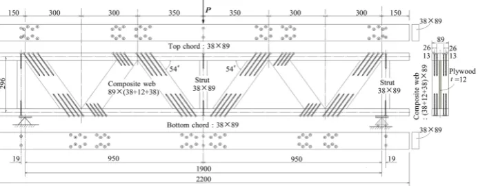
The configuration of wooden parallel chord truss was determined to have a span length of 1900 mm and a depth between top-chord and bottom-chord of 296 mm subject to a central point loading as shown in Fig. 2a. The main reason to choose this configuration was due to the capacity of the testing machine that could be used for this study. Fig. 2b emphasizes the difference of kind, number and allocation of STS at nodal point.
Number of STS per nodal point was set as the experi-mental parameter starting from 2rows-2lines (total 4STS) until 2rows-4lines (total as 8STS). As sufficient cross-sectional area was required to penetrate multiple STS into the nodal point, diagonal member was designed as “composite web” using double 38 mm by 89 mm solid Canadian spruce lumbers with nail-glued 12 mm plywood for a spacer shim as shown in the drawing at right edge of Fig. 2a. Using this type of wider cross-sectional web mem-ber, multiple STS could be penetrated into the nodal point. The tensile nodal joints were all composed of multi-ple longer STS of 140 mm length, while the compres-sive nodal joints were composed of shorter STS of 80 mm length. The first specimen IST-2-1 was fabricated using partially threaded STS having 8 mm diameter as a trial. IST-2-2, IST-3-1, IST-4-1 and IST-4-2 specimens were fabricated using full-threaded STS of 5 mm diameter.
The difference between IST-4-1 and IST4-2 was on the allocation of STS at nodal point. Allocations of 4lines STS in IST-4-1 specimen were staggered 1.0d apart as shown in Fig. 2b, while those of IST-4-2 specimen were stag-gered 2.6d apart as shown in Fig. 2b, in which “d” was the nominal diameter of STS.
The distance between nodal points at central part of upper chord was 350 mm and this was 50 mm longer than other part (300 mm) to avoid concentration of multiple STS in the bottom tensile nodal point at mid-span, therefore, location of struts at both supports were shifted to outside by 19 mm as shown in Fig. 2a. Replication of each truss specimen was one.
Materials
Chord, part of web and strut
Canadian spruce (Picea glauca (Moench) Voss) 2 by 4 dimension lumbers, having the nominal cross section of 38 × 89 mm, imported from Canada, were used for all chord members, struts and outer parts of composite web members. Larch plywood of 12 mm thickness produced in China was used for the inner part of the composite web member.
Modulus of elasticity of materials was measured using the 4-points edgewise bending test with 1600 mm span length (18 times of member height) in accordance with Chinese standard GB/T 50329 [27] before truss specimens were fabricated. Density and moisture contents of materials were measured on the 20 mm cubic specimens taken from destroyed parallel chord truss specimens in accordance with GB/T 1933 [28] and GB/T 1931 [29], respectively. Table 1
shows mean values of the mechanical and physical proper-ties of members used in the parallel chord truss specimens.
Composite web
Diagonal web members were composed of double 2 by 4 edgewise solid lumbers sandwiching with single plywood shim to obtain enough cross-sectional area for penetrating multiple STS. Assembly of solid lumbers and plywood was done using a vinyl acetate resin emulsion adhesive and sev-eral short screws to obtain a perfect composite cross-section. The apparent modulus of elasticity of the composite web
members Ecomp is derived in Eq. (1) assuming that the three parallel members could share a common deformation due to perfect adhesive joint with each other.
where, ECS modulus of elasticity of Canadian spruce 2 by 4
lumber [N/mm2], E
PW modulus of elasticity of edgewise ply-wood [N/mm2], A
CS area of single Canadian spruce member [mm2], A
PW area of plywood member [mm2], Aweb area of
composite web member (= 2 ACS + APW ) [mm2].
STS
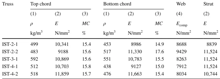
In this study, two different kinds of STS were used. For IST-2-1 specimen (first trial specimen), partial threaded STS having a nominal diameter of 8 mm and length of 80 mm and 140 mm made in China were used. For IST-2-1, IST-3-2, IST-4-1 and IST-4-2 specimens, full-threaded STS having nominal diameter of 5 mm and length of 80 mm and 140 mm made in Italy were used. Fig. 3a, b show photos of screws used in this study.
Measurements of deflection, relative slip and strain in truss specimen
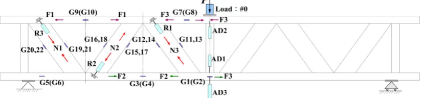
To record the flexural behaviour of wooden parallel chord truss, load–deflection relationship at mid-span, axial force–slip relationship between chord and diagonal web, member strains relating to the estimation of eccentric moment at nodal points were measured using a load-cell, deflection measuring devices, and strain gauges at the loca-tions shown in Fig. 4a–c.
Eccentric moment caused by continuity of chord and eccentric allocations of nodal points was tried to measure by a pair of strain gauges glued on the lower surface and on the 5.5 mm inner side surface of the target point along (1) Ecomp =
(2E
CS⋅ACS+EPW⋅APW Aweb
)
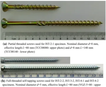
Table 1 Mechanical and physical properties of members used in parallel chord truss specimens
(1) Density, (2) modulus of elasticity parallel to the grain, (3) moisture content at test, (4) apparent modu-lus of elasticity of composite web member [refer to Eq. (1)]
Truss Top chord Bottom chord Web Strut (1) (2) (3) (1) (2) (3) (4) (2)
ρ E MC ρ E MC Ecomp E
kg/m3 N/mm2 % kg/m3 N/mm2 % N/mm2 N/mm2
chord member as shown in Fig. 4c and moment is estimated by Eq. (2).
where, 𝜀upper strain at upper surface = ( 38∕2 38∕2−5.5
)
⋅𝜀side = 1.4⋅𝜀side , 𝜀side : strain measured at 5.5 mm inner side surface
of chord (refer to Fig. 4c), 𝜀lower strain measured at lower
surface, Zchord section modulus of chord member (mm3), Echord modulus of elasticity of chord member (N/mm2).
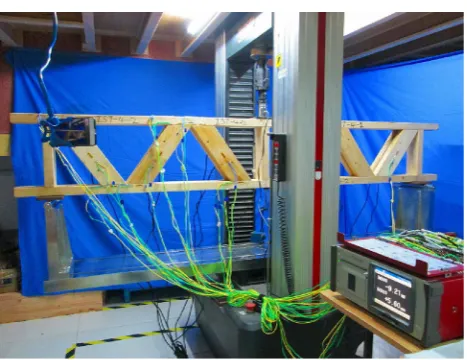
Figure 5 shows a feature of testing machine, test set-up and data acquisition system used in this study. All tests were executed under a monotonic loading protocol with a cross-head speed of 2 mm/minutes.
Fundamental joint test of nodal point
After the destructive experiments on the parallel chord trusses were finished, fundamental joint tests of the nodal point were done using chord materials taken from undam-aged parts of destructed specimens and adding new Cana-dian spruce 2 by 4 lumbers as the diagonal web member. The line number of STS per row in the joint varied from 1 to 4 as the experimental parameter. Specifications of the (2) M= 1
2(𝜀upper−𝜀lower)⋅Zchord⋅Echord
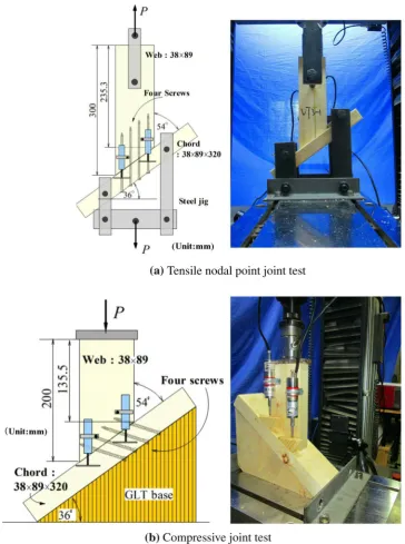
fundamental joint test are tabulated in Table 2. In the case of fundamental joint test, diagonal web was not the com-posite section but single solid lumber was used. Fig. 6a, b show outline of the fundamental joint tests in the case of 4lines STS (VT4 and VC4 specimens) as examples. Rep-lication of each joint test specimen was three.
Finite element method
Chord–web joints
Nonlinear behaviour of test specimens was analyzed using a FEM program [30]. In the program, chord–web joints were modeled as nonlinear axial springs. Transmissions of shear force and moment between chord and diagonal web member were not considered. Force–slip relation-ships of the spring used in tensile and compressive joints were expressed by a tetra polygonal-line approximation model which was packaged in the FEM program [30]. All parameters necessary for describing the tetra polygonal-line approximation model were determined so as to fit the average force–slip curves obtained from the fundamen-tal joint tests. Fitting operations were done based on the visual decisions of the first named author.
Material nonlinearity of chord member
Material nonlinearity was considered only in the chord members by employing fiber model [31, 32] which was installed at both nodal points of chord element so as to have a length of h/2 (h is depth of member, and quantity of h/2 was recommended in the program [30]) as shown in Fig. 7. Strain in a fiber slice was expressed using curvature 𝜙x , axial strain 𝜀0 , and coordinate value of i-th fiber slice
(yi,zi) as shown in Fig. 7. Using the fiber model, axial and
bending interacting stress was automatically evaluated. Stress–strain relationship in a fiber slice of Canadian spruce was deduced as follows;
1. Modulus of rapture Fb and compressive strength parallel
to the grain Fc were presumed via specific gravity G of
chord member based on the regression Eqs. (3) and (4) which were presented in US Wood Handbook [33].
2. Tensile strength Ft was presumed based on the widely
used ratio [34–37] between bending strength and tensile strength.
(3)
Fb=170.7⋅G1.01
(4) Fc=93.7⋅G0.97
3. Compressive proportional limit stress Fy was presumed
based on the research results of Sawada [37].
4. Strain at maximum compressive strength was presumed based on the research results of Sawada [37].
From the above-mentioned assumptions, stress–strain relationship of fiber slice of Canadian spruce will be able to be described schematically as shown in Fig. 8. In the tensile stress–strain region, after stress value reached at Ft, tensile
(5)
Ft=0.6⋅Fb
(6)
Fy=0.79⋅Fc
(7)
𝜀0 =1.1764⋅ (F
c
E )
stress was controlled so as to decrease toward the target strain of 30Ft/E.
Results and discussion
Validity of stress–strain relationship used in the fiber model
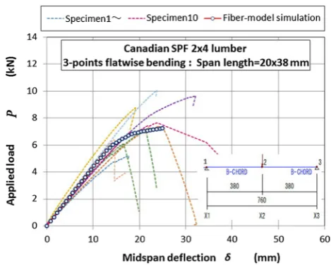
Validity of stress–strain relationship used in the fiber model was evaluated by comparing FEM simulation result and experimental raw data provided by the Canadian research team. The Canadian experiment was done by flat-wise three points bending test method with 20 h span length (h: beam depth) on Canadian SPF 2 by 4 dimension lumbers whose average specific gravity was 0.47 and average MOE was 10.5 MPa. Figure 9 shows comparison between FEM simulation (solid line with markers) and experimental 10 results (dashed lines). FEM calculation was done using a simplest 2-elements FEM model whose mechanical prop-erties were deduced by Eqs. (3) to (7) via given specific gravity and MOE subject to a central incremental deflec-tion of -0.001 mm. As good agreement was recognized, the same estimation method for the material properties of chord members was applied to each FEM model for the parallel chord truss tested.
Results of fundamental joint tests
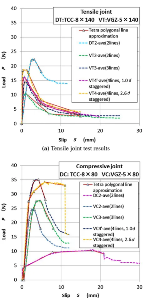
Fig. 10a, b show results of fundamental joint test and tetra polygonal-line fitting situations.
Except DT2 specimen, initial slip region of all tensile joints showed almost less than 1 mm, and after exceeded maximum value, load carrying capacity decreased steeply until almost half of the maximum value, then slowly decreased once again. As the STS used for DT2 specimen had trumpet-shaped wider screw head as shown in Fig. 3a, pull-through resistance by screw head was remarkable so that DT2 only showed large deformation ability without load reduction until 18 mm slip as shown in Fig. 10a and Fig. 5 Feature of testing machine, test set-up and data acquisition
sys-tem used in this study
Table 2 Specifications on the fundamental joint tests (replication numbers: 3)
(1) Specimen code name, (2) number of STS per joint, (3) STS code name, (4) remarks Tensile joint Compressive joint
(1) (2) (3) (4) (1) (2) (3) (4)
DT1 1 TCC08140 Not used for the analyses DC1 1 TCC08080 Not used for the analyses DT2 2 TCC08140 DC2 2 TCC08080
VT1 1 VGZ-5 × 140 Not used for the analyses VC1 1 VGZ-5 × 80 Not used for the analyses VT2 2 VGZ-5 × 140 VC2 2 VGZ-5 × 80
VT3 3 VGZ-5 × 140 VC3 3 VGZ-5 × 80
finally splitting failure occurred at chord member. On the other hand, STS used for VT specimens had cylinder-shaped slender screw head as shown in Fig. 2b. Hence pull-through resistance of screw head was not so expected like the case of DT2 and both withdrawal of threaded part from web member and embedment of cylinder head into chord member were occurred until loading was stopped. Due to this configurational difference, charac-teristic load–slip curves of these two types of joint speci-mens were appeared. For the tensile joint specispeci-mens, the increase of number of screw, as well as pitch in staggered allocation, clearly made initial stiffness and maximum
strength increased. The effect of those was much larger for the stiffness than the strength.
While in the case of compressive joint, initial slip region was 2–3 mm then showed gradual load increasing region until maximum value. After reaching the maximum value, load decrease was not so steep like tensile joint. Load reduc-tion occurred due to pushing out of edge-side timber by an inner bent STS as sliding down movement of web member increased. Some specimens finally failed by sprit at the edge-side surface.
As the actual joints at all nodal points of test specimens had 2rows-multi (2–4) lines STS allocations, all load values Fig. 6 Fundamental joint test of
determined in the tetra polygonal-line approximations were multiplied by 20.9 = 1.866 in accordance with the rule in Eurocode 5 [38].
Comparisons between experimental observations and FEM calculations
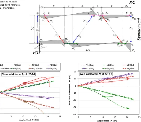
Definitions of axial forces and nodal moments
Figure 11 shows definitions of axial forces and nodal point moments in the left-half side of parallel chord truss ana-lyzed. In this figure, Fi (i = 1–4) is axial force in the chord member, Ni (i = 0–4) is axial force in the diagonal web mem-ber and strut, Mi (i = 2–10) is eccentric moment at nodal
point which is thought to be caused by continuity of chord member and also eccentric allocations of modal points.
Axial forces in members
Comparisons between axial forces observed by strain gauges and those calculated by FEM could be done only in the case of IST-2-1specimen (first trial specimen), because strain gauges for measuring axial forces in chord and web member were only put on the IST-2-1 specimen as shown in Fig. 4a.
Figures 12 and 13 show these comparisons. Agreements between observed axial forces in members (dashed lines) and calculated values (solid line with marker) are almost good except the case of compressive force N2 in the diago-nal web as shown in Fig. 13.
Bending moment at nodal points
As the absolute values of bending moments at nodal points measured by a pair of strain gauge were almost half of those calculated by FEM, we judged that results Fig. 7 Element with fiber slices at both nodal point I and J
Fig. 8 Schematic diagram of stress–strain relationship of fiber slice
of the observed moment were not enough for presenting in this article. This might be a limitation on the accuracy of strain gauge put on this kind of strain field where strain values vary steeply within relatively short region.
Load–deflection, slip at nodal points, fiber stress and final failure phenomena
Figures 14, 15, 16, 17 and 18 show nonlinear behaviors of each test specimen separately. Comparisons between observed load–deflection relationship (solid line) and computed ones (dotted line) including most critical fiber stress (dashed line) as well as observed slip at nodal points (dashed line) and computed ones (solid line with markers) accompanying with photo showing final failure phenom-ena are to be shown at the same time to understand the interactive effects from both joint performance and mate-rial nonlinearity. Locations of slip measuring device Ri are shown in Fig. 4a, b.
IST-2-1 specimen As IST-2-1 specimen composed of par-tially threaded STS whose tensile load–slip relationship was peculiar as seen in Fig. 10a, it showed clear nonlinear behavior from lower applied load level as can be seen from Fig. 14a as the STS had especially lower yield strength. Fig. 14b shows good agreement between observed slip and calculated one was obtained until P reached at 20 kN. Fig. 14a, b show that stress level of the most critical fiber slice was about 67% of its failure level (ft = 0.67Ft) at P = 20 kN level. Afterwards, as the actual tensile joint had already reached to its maximum pull-out capacity, fatal pull-out of STS occurred by accompanying with bottom chord bending failure as shown in Fig. 14c although FEM continued calculation as if there was still some safety mar-gin in tensile joint capacity.
IST-2-2 specimen Fig. 15b describes that when P reached at 20 kN, tensile nodal joint of IST-2-2 specimen was largely pulled out so that stress distribution in the bottom chord changed drastically hence stress in the most critical fiber slice in the bottom chord suddenly rose up to its criti-cal value (ft=Ft) as shown in Fig. 15a. Afterwards, bend-ing failure phenomena gradually progressed as shown in Fig. 15a, c. FEM could qualitatively predict these phe-nomena well, but could not do quantitatively well.
IST-3-1 specimen Fig. 16a–c describe the nonlinear behaviors of ITS-3-1 specimen. The nonlinear behaviors of this specimen are similar to those of ITS-2-2. Namely, when P reached at 29 kN, tensile nodal joint was largely pulled out so that bottom chord subjected to mostly com-pressive force due to re-distribution of axial force, after-ward bottom chord fiber slice reached its critical value (ft = Ft) when δ reached at 27 mm, then bending failure pro-gressed gradually as shown in Fig. 16a and finally load carrying capacity of bottom chord was lost. FEM could qualitatively predict these phenomena very well but not quantitatively perfect.
Fig. 10 Results of fundamental joint test and tetra polygonal-line
IST-4-1 specimen ITS-4-1 specimen behaved quite differ-ently from FEM prediction. As can be seen from Fig. 17b, in this specimen, tensile joint was not pulled-out largely even when P reached 30 kN. While at this instant, fiber stress at bottom of mid-span once reached to its critical value (ft = Ft) but soon stress decreased till about ft=0.82Ft and this level was kept until δ reached to 60 mm. During this term, the so-called “plug-shear” failure occurred at a tensile joint in the bottom chord near the mid-span as shown in Fig. 17c due to 1.0d narrow staggered allocation of STS as shown in Fig. 2b. In consequence, FEM predicted a kind of bi-linear rising load–deflection curve while reality on specimen was quite different as shown in Fig. 17a, c. Fiber model used could not correspond against “plug-shear” failure at all.
IST-4-2 specimen In the case of IST-4-2 specimen, STS allocation was staggered with 2.6d (d is screw diameter)
apart as shown in Fig. 2b so that no more “plug-shear” failure occurred. Failure mode was a pure tensile failure in the bottom chord member near the mid-span as shown in Fig. 18c. In this specimen, pull-out of the tensile nodal joint was scarcely observed as shown in Fig. 18b. Therefore, the cause of nonlinear behaviors was entirely due to mate-rial nonlinearity. Stress in the most critical fiber slice near the mid-span once it reached nearly its critical value ft = Ft when P reached at 30kN, afterward, pure tensile failure occurred by rising up of tensile stress, although FEM did not predict so rigorously.
Comparisons among five specimens
Figure 19 shows load–deflection curves observed on the five different truss specimens. In this section, comparisons are to be done based on this figure.
Fig. 11 Definitions of axial force and nodal point moments in the parallel chord truss analyzed
Fig. 12 Axial forces observed (dashed line) and those calculated by
Comparing IST-2-1 and IST-2-2, although both were composed of same numbers of STS but having different thread profiles, it can be seen that IST-2-1 showed lower stiffness due to less threaded part length but very rich duc-tility due to embedment resistance of trumpet-shaped screw head.
Comparisons among IST-2-2, IST-3-1 and IST-4-2, hav-ing a proportional number of STS with sufficient space with each other, imply that stiffness and strength were likely to be simply proportional to the numbers of STS used for compos-ing nodal joints.
Comparing IST-4-1 and IST-4-2, although both were composed of same numbers of STS but having different space of staggered allocations, it was clear that perfor-mance of IST-4-1 was inferior to that of IST-4-2 because IST-4-1 was staggered with 1.0d apart, while IST-4-2 was staggered with 2.6d apart, consequently there was a large difference between IST4-1 and IST4-2 on stiffness, fail-ure phenomenon and strength.
Summaries
From experimental and numerical investigations on wooden parallel chord truss composed of STS, following findings might be summarized.
1. Agreements between observed axial forces measured by strain gauges and those of calculated by FEM were good, although there were some discrepancies.
in FE-Model, slip behaviors at nodal points of wooden parallel chord trusses were reasonably expressed. 3. Implementation on the nonlinear behaviors of wooden
parallel chord trusses was done using both observed results and FEM results. In some extent, this approach could explain nonlinear behaviors reasonably. In the final stage of the failure, however, predicting abilities
of FEM were not enough probably due to insufficient information about failure criteria of Canadian spruce used in the experiments.
4. Numbers of STS composing nodal joint were simply proportional to the stiffness and strength of wooden par-allel chord trusses.
5. Material nonlinearity gave less effect on the total nonlin-ear behaviour of the specimens when joint performance was inferior, on the other hand, as the joint performance
increased material nonlinearity gave dominant effect on the total nonlinear behaviour of the specimens.
Acknowledgements This work was financially supported by the
Spe-cial Fund for National Natural Science Foundation of China (Pro-ject No.31670566, Principal researcher: Professor Que Zeli). Full-thread screws used in this research (VGZ-series) were all provided by Rothoblaas®, Italy. Raw data on Canadian SPF 2 by 4 dimension
lumbers subject to flatwise bending load were provided by courtesy of Professor Chui’s research team in Canada. Authors would like to express their sincere thanks to all these supports.
References
1. Blass HJ, Bejtka I (2001) Screws with continuous threads in timber connection. In: Proceedings PRO 22: international RILEM symposium on joints in timber structures. Stuttgart, Germany, pp 193–201
2. Ringhofer A, Brandner R, Schickhofer G (2015) Withdrawal resistance of self-tapping screws in unidirectional and orthogo-nal layered timber products. Mater Struct 48:1435–1447 3. Bejtka I, Blass HJ (2002) Joints with inclined screws. In: Proc.
of the CIB-W18 Meeting 35, Paper No. CIB-W18/35-7-5, Kyoto, Japan
4. Johansen KW (1949) Theory of timber connections. In: Inter-national association of bridge and structural engineering, Bern, Switzerland, Publication No.9, pp. 249–262
5. Kevarinmäki A (2002) Joints with inclined Screws. In: Proceed-ings CIBW18 Meeting 35, Paper No. CIB-W18/35-7-4. Kyoto, Japan
6. prEN 1995-1-1, Eurocode 5 (2002) – Design of timber struc-tures—Part 1–1: general rules and rules for buildings. Final Draft, Version 2002-02-28. The European Standard, Brussels 7. Tomasi R, Piazza A, Angeli A, Mores M (2006) A new ductile
approach design of joints assembled with screw connectors. In: Proc. of World Conference on Timber Construction 2006, Portland, OR, USA, August 6–10
8. Opazo AV, Bustos CA (2008) Study of the lateral strength of timber joints with inclined self-tapping screws. In: Proceedings of the 51st International Convention of Society of Wood Science and Technology, November 10–12, Concepción, Chile 9. Pirnbacher G, Brandner R, Schickhofer G (2009) Base
param-eters of self-tapping screws. In: Proc. of the CIB-W18 Meeting 42, Paper No. CIB-W18/42-7-1, Dübendorf, Switzerland
10. Frese M, Blass HJ (2009) Models for the calculation of the withdrawal capacity of self-tapping screws. In: Proc. of the CIB-W18 Meeting 42, Paper No. CIB-W18/42-7-3, Dübendorf, Switzerland
11. Krenn H, Schickhofer G (2009) Joints with inclined screws and steel plates as outer members. In: Proc. of the CIB-W18 Meeting 42, Paper No. CIB-W18/42-7-2, Dübendorf, Switzerland 12. Tomasi R, Crosatti A, Piazza M (2010) Theoretical and
experi-mental analysis of timber-to-timber joints connected with inclined screws. Constr Build Mater 24:1560–1571
13. Jockwer R, Steiger R, Frangi A (2014) Design model for inclined screws under varying load to grain angles. In: International net-work on timber engineering research, INTER/47-7-5, 1st INTER Meeting, A. September, Bath, United Kingdom
14. Ringhofer A, Schickhofer G (2014) Investigations concerning the force distribution along axially loaded self-tapping screws, materials and joints in timber structures—recent developments of technology. In: Aicher S, Reinhardt HW, Garrecht H (eds) RILEM Bookseries 9. Springer, New York
15. Jockwer R, Steiger R, Frangi A (2014) Fully threaded self-tapping screws subjected to combined axial and lateral loading with dif-ferent load to grain angles, materials and joints in timber struc-tures—recent developments of technology. In: Aicher S, Reinhardt HW, Garrecht H (eds) RILEM Bookseries 9. Springer, New York 16. Girhammar UA, Jacquier N, Källsner B (2017) Stiffness model for inclined screws in shear-tension mode in timber-to-timber joints. Eng Struct 136:580–595
17. Brandner R, Ringhofer A, Grabner M (2018) Probabilistic models for the withdrawal behavior of single self-tapping screws in the narrow face of cross laminated timber. Eur J Wood Prod 76:13–30 18. Blass HJ, Bejtka I (2004) Reinforcements perpendicular to the
grain using self-tapping screws. In: Proceedings of world confer-ence on timber construction 2004, Lahti, Finland, June 14–17, pp 1001–1006
19. Jönson J, Thelandersson S (2005) Load carrying capacity of curved glulam beams. In: Proc. of the CIB-W18 Meeting 38, Paper No. CIB-W18/38-7-3, Karlsruhe, Germany
20. Jönson J (2005) Load carrying capacity of curved glulam beams reinforced with self-tapping-screws. Holz als Roh- Werkstoff 63:342–346
21. Blass HJ, Schmid M (2001) Self-tapping screws as reinforcement perpendicular to the grain in timber connections. In: Proceedings PRO 22: International RILEM symposium on joints in timber structures. Stuttgart, Germany, pp 1–10
22. Bejtka I, Blass HJ (2005) Self-tapping-screws as reinforcements in connections with dowel-type fastener. In: Proc. of the CIB-W18 Meeting 38, Paper No. CIB-W18/38-7-4, Karlsruhe, Germany 23. Mohammad M, Salenikovich A, Quenneville P (2006)
Investiga-tions on the effectiveness of self-tapping screws in reinforcing bolted timber connections. In: Proc. of world conference on timber construction 2006, Portland, OR, USA, August 6–10, Connections VI
24. Bejtka I, Blass HJ (2006) Self-tapping-screws as reinforcements in beam supports. In: Proc. of the CIB-W18 Meeting 39, Paper No. CIB-W18/39-7-4, Florence, Italy
25. Blass HJ (2012) Beams and trusses for timber buildings. In: Key-note Lecture, World Conference on Timber Construction 2012, 15–19 July, Auckland, New Zealand, http://www.confe rence .co. nz/files /docs/wcte1 2/hans%20bla ss%20wct e%20201 2%20key note. pdf. Accessed 26 June 2018
26. Stamatopoulos H, Malo AK (2015) Withdrawal capacity of threaded rods embedded in timber elements. Constr Build Mater 94:387–397
27. GB/T 50329 – 2012 (2012) Standard for test methods of timber structures (in Chinese). China Building Industry Press, Beijing
28. GB/T 1933–2009 (2009) Method for determination of the density of wood (in Chinese). Standards Press of China, Beijing 29. GB/T 1931–2009 (2009) Method for determination of the
mois-ture content of wood (in Chinese). Standards Press of China, Bei-jing, China
30. Kozo System (ed) (2018) Technical manual for structural non-linear analysis program (SNAP) ver.7.0.1.2 (in Japanese), Kozo System Inc.
31. Li KN, Kubo T (1998) Reviewing the multi-spring model and fiber model. In: Proc. of The 10th Japan Earthquake Engineering Symposium, Vol. 2, pp 2369–2374
32. Spacone E, Fillipou FC, Taucher FF (1996) Fiber beam–column model for nonlinear analyses of R/C frames: part I, formulation. Earthq Eng Struct Dyn 25:711–725
33. Forest Products Laboratory (ed) (1999) Wood handbook—wood as an engineering material, Gen. Tech. Rep, FPL–GTR–113. U.S. Department of Agriculture, Forest Service, Madison
34. ANON (2009) Design data-I, Characteristic strength of softwood solid timber (in Japanese). In: Architectural Institute of Japan (ed) standard for structural design of timber structures, Maruzen, Tokyo
35. Porteous J, Kermani A (2013) Structural timber design to Euroc-ode 5, 2nd edn. Blackwell Publishing Ltd, West Sussex
36. Walford GB (2003) Comparison of Various Standards for the Characteristic Strength and Stiffness of Structural Timber. NZ Timber Design J 11(2):13–18
37. Sawada M (1958) Studies on the mechanical characteristics of woods—mainly, as affecting’ factors of wood beams. (in Japa-nese) Research Report of Forest Research Institute, vol 108, pp 115–224
![Fig. 1 Concept of glulam paral-lel chord truss introduced by Blass [by K. Komatsu based on the original image by Blass [28]](https://thumb-us.123doks.com/thumbv2/123dok_us/904068.1588041/2.595.186.544.545.713/concept-glulam-paral-introduced-blass-komatsu-original-blass.webp)