http://www.sciencepublishinggroup.com/j/ijecec doi: 10.11648/j.ijecec.20190501.11
ISSN: 2469-8040 (Print); ISSN: 2469-8059 (Online)
Enhancement of Power Generation for PV Systems Using
Dynamic Tacking System
Ayman Mohammad Brisha
Electronics Technology Department, Faculty of Industrial Education, Beni Suef University, Bani Sweif City, A.R.E.
Email address:
To cite this article:
Ayman Mohammad Brisha. Enhancement of Power Generation for PV Systems Using Dynamic Tacking System. International Journal of Electrical Components and Energy Conversion. Vol. 5, No. 1, 2019, pp. 1-9. doi: 10.11648/j.ijecec.20190501.11
Received: December 19, 2018; Accepted: March 20, 2019; Published: May 8, 2019
Abstract:
The objective of this research is tracking power obtained daily (March-September 2017 in Mansoura state) from moving solar panel system during 12 hrs. to enhance power gain. The automatic sun tracking system provides peter alignment of solar panel with the sun. The aim of designing and implementing technology an automatic dual-axes tracking mechanism though chaining the sun tilt-angle due to change of both the seasons and day time is to improve maximum power gain from sun. This proposed system is added to determine the exact time of cleaning process based on real-time clock (RTC). The reading of power output from the proposed system gives a power gain of 74% more than power gain of a fixed solar panel. The proposed solar system design has low consumed power, minimum cost, reliable structure and residential usage applications. The practical experiment proves that all critical points which obtained from moving solar system is better than fixed solar system.Keywords:
Solar Energy, Photovoltaic, Dynamic Tracking Systems, PIC Micro-controller, Self-cleaning, Dust Effects1. Introduction
Solar energy technology is one of the important expected sources of future energy supplies, because not only it is a valid supply of nonpolluting source but also the limited supply sources of non-renewable fuels.
Also, fossil fuels have many side effects due to combustion products that produce pollution which cause acid rains and global warming. Therefore, solar energy conversion is one of the clean energy sources which would enable the world to improve the life quality all over the earth planet [1].
The generated electric power using a photovoltaic power generation system can be used for many applications, such as water desalination, domestic water heating, and power generation [2]. Solar Tracking System technology enhance the efficiency of the solar cells by tracking the sun [3]. There were many ways for maximizing the rate of useful energy; optimizing the conversion of the absorber level by properly choosing the absorber materials, and increasing the incident radiation rate by using tracking systems, and many other methods were reported [4]. Tracking systems are mechanical systems that incorporate mechanics, electronics, and information technology. These mechanisms were driven by rotary or linear actuators, which controlled to ensure the
optimal positioning of the PV modules [5, 6].
Solar cells were fixed on different conventional places, such that fixed panels which were commonly placed at equal latitude tilt angle. As a result, solar cells were unable to receive maximum light because the position of sun changed with time. Since the energy conversion was more efficient when the rays fell vertically on the solar panels [7].
Sun radiation position varies with both time and seasons of the day. Solar cells are conventional fixed on different places, such that the commonly fixed panels are fixed at equal latitude tilt angle. As a result, solar cells are unable to receive maximum light because the position of sun changes with time. Energy conversion is more efficient when the rays fall perpendicular on the solar panels [8].
Sun tracking systems had been studied for different applications to improve the efficiency of solar system by adding tracking equipment's to these systems. A tracking mechanism must be reliable and able to follow the sun with certain degree of accuracy and returns the solar panels, (or flat-plate collector), to their original position at the end of the day, (or during the night). Also tracking during cloud covered [9].
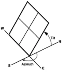
The tilt angle of this axis equals the latitude of the installation site facing directly to the sun; in consequence to this type of tracking system a seasonal tilt angle adjustment is necessary. Therefore, the dual-axis tracking systems which have two degrees of freedom that acts as axes of rotation. Also, these trackers are able to precisely follow the sun path along the period of one year. This is why the dual-axis tracking systems are more efficient than the single one, in spite that they are more expensive because of the usage of expensive components in the system [10]. Figure 1 illustrates the tracking systems.
Figure 1. Track systems.
Generally solar tracking systems will increase the efficiency of the solar panel by 20-62% higher than that of the fixed systems, depending on where you are in the world. Solar trackers were basically microcontroller or sensor based, (in some cases passive tracking systems were used. In microcontroller based systems, different mathematical calculations were used to get the sun’s apparent position according to the programming logic which track sun. In case of sensor based systems the sun was tracked depending upon the signal from the sensors integrated in the system. Typically, the sun sensors were mounted on the controller base or around the panel itself, and were used to feed information regarding the amount of sunlight. This information which (was) is in a form of analogue to digital conversion, ADC, was fed into a closed loop control circuit, where, the amount of sunlight was used to continuously monitor the position of the sun [11].
Previous work researches, related to solar tracking system was investigated the control of two-axis tracking system and used LDR relays and microcontroller. Where, stepper motor is used to move the system panel, the result of output power about 30-45% [12]. Using the pilot scheme as a search technique, LDR as a detector for the sun rise and set, the PIC18f452 microcontroller to control the solar panel and pilot movement, the DC motors also (were) used [13].
The dual-axis solar tracker in this study is the angular height position of the sun in the sky in addition to following the sun’s east-west movement. The gain of the dual-axis tracking system is about 40% compared with the fixed system, The gain of the single- axis tracker systems is about 28% compared with the fixed system, so a compromise between maximum power collection and system simplicity is obtained [14].
Micro Controller Based Solar Tracking System using DC gear Motor, the efficiency of Micro Controller Based Solar Tracking System is improved by 24%. This tracking system does track the sun in a continuous manner. And this system is
more efficient and cost effective in long run [15].
2. Problem Description
The conversion principle of solar light into electricity, (which is called Photovoltaic, PV, conversion), is not new, but the efficiency improvement of the PV conversion still one of top priorities for many academic and/or industrial research groups all over the world. Among the proposed solutions for improving this efficiency is solar tracking [16]. Trackers direct solar panels or modules toward the sun for changing their orientation through the day for maximizing energy capture. The accumulation of dust on the surface of solar panel reduces the efficiency by 30% in high dust areas. A self-cleaning system is also, proposed to maintain the stability of the output power all over the year.
3. The Proposed System Description
The project which is based on microcontroller and light sensors, will develop a dual-axis sun tracking system where design and study of a seasonal angle (tilt angle) at different conditions is considered.
The main objective of the proposed design is to develop the performance of sun tracking system to improve the efficiency of overall electricity generated from the solar energy. Using a proposed dual-axis tracking at two conditions only of seasonal angle (tilt angle) which changes the daily at noon time and at the beginning of the changing seasons (like summer or winter). The PV solar panel will be tilted around the x-axis through June 21 to December 21 (2017) in one direction and through December 22 to June 20 in the opposite direction [17]. The electromechanical system of this proposed tracking system is very simple and easy used in residential societies. It consists of two drivers, (DC-motors), of 12 V, the first is for adjusting the tilt angle and the second is for the east-west, E-W, tracking.
The main components of the control circuit are; LDR, Potentiometers, Dual Full-Bridge Driver L298, RTC, PIC microcontroller, batteries, charge regulator, low power liquid crystal display, LCD, and DC geared motors. The three LDRs each acts as a sensor; one for judging the weather (cloudy or sunny), and others are responsible for tracking sun from east to west. The programming of PIC18F452 will calculate the voltage difference between east-west sensors and give a pulse to the L298 for moving both the E-W motor and north-south, N-S, liner actuator motor.
The effect of dirt and dust on the efficiency of the generated electricity that represents the maximum output of the solar panel is considered. The microcontroller software program is developed to read data from RTC to solve the problem of reducing the output power due to accumulation of dust determines the cleaning periods, and to update the PV panel position through both the seasonal and the day hors.
4. System Design
The controller board consists of three parts as shown in Figure 2; the PIC microcontroller, the sensing part, and the motors. The tracking proposed system is a combination of the active and passive tracking systems. It is composed of photoelectric tracking of daily and tilt angles. It has advantages of all the advantages of the passive and active systems in order to make the proposed system more accurate and stable.
The proposed system consists of three LDRs which produce the input signals to the PIC unit; as clear in item 3, moreover day/night are determined and consequently it can deal with the problem of battery usage; whether the main or the spare battery.
The microcontroller gives the output signals required to drive the DC motors, (geared & linear actuator), to adjust the panel position according to the schedule of the natural direction of the sun to adjust the tilt angle.
Figure 2. Block diagram of the proposed automatic solar tacking system based on PIC microcontroller.
The RTC gives the current date and time database to microcontroller using inter integrated circuit (I2C) transmitting method. The microcontroller's proposed software is developed for adjusting the tilt-angle at the beginning of March 30 and continue tile Sept. 12 (2017).
More detailed schematic diagram of the proposed automatic solar tracking is shown in the following Figure (Figure 3), where its main components are summarized as;
4.1. Sensors and Limit-Switches
The LDRs are placed as shown in Figure 4.
Figure 4. Proposed tracking sensor model.
The E-W LDR sensors are separated by holder which will create shadow on one of the LDRs if the solar panel is not perpendicular to the sun rays results in difference of the value of the resistance between two LDRs. See Figure 5.
Some Improvements were added to raise the sensitivity of light by laying the LDR inside a plastic tube.
Figure 5. Shadow effects.
so as to increase the shadow. The ratio between the height of the holder and that of the tube is taken as 1:2.
Each LDR sensor is placed in series with a resistor of 10KΩ to form a voltage divider. The output analogue voltage of this combination is given by the following equation, (Eq.
1). And is connected to the PIC through analog to digital converter, ADC, pin.
∗
Ω (1)
Where; VReference is equal to VDD considered +5 V. these
analogue voltages are converted into digital value according to following equation, (Eq. 2).
!"#$%&'∗ '(')'!*'
+,-. (2)
PIC will activate the E-W motor direction Based on both E-W LDRs and weather LDR; when the output voltage of the weather LDR is greater than or equal to Threshold Value (which is an integer). If the E-W LDR sensors give the same output voltage, thus the motor is stopped, also if the output voltage of the weather LDR is less than the threshold Value, this means that a cloudy day [18].
The E-W motor stops if the atmosphere remains cloudy for more than 60 minutes, where this system able to move the solar panel toward the ideal situation and set it at an angle, 45°, towards the south (in fixed systems of Egypt site) and then re-search process.
4.2. Main Controller and Motor Drive Circuit
Control board is responsible for giving the required orders processing information coming from the light sensors, and from the other parts, and the motor drive circuit consists of three transistors, L298 dual H-bridge and external bridge of diodes, as shown in Figure 6 to control the direction through operating motors.
Tracking system is controlled by micro-controller with necessary interface. Limit switches are used to bring back the panel to morning position after each day without human interference [19].
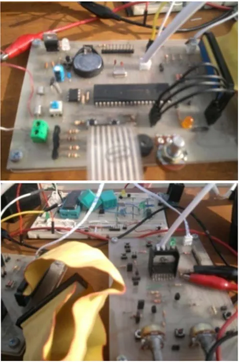
PIC is used to control the rotation of the platform (in bidirectional), and send data to form the DC-geared motor and the linear actuator to make the solar panel perpendicular towards the Sun. DC-geared motor is connected to L298 to control the rotation of the DC-motor, i.e., its terminal voltage of out1 or out2 is positive the motor turns either to clockwise or anticlockwise, Figure 7 shows the hardware circuits of controller and L298 DC-Motors driving, whereas signal from its terminal out3 and out4 [20].
Figure 7. H/W circuits of controller for L298 and DC motors driving.
The external bridge of diodes D1 to D4 is made by four fast recovery elements that must be chosen of a voltage flower, VF, as low as possible at the worst case of the load current. The brake function (Fast motor stop) requires that the absolute maximum rating of 2 Amps must never be overcome.
DC- motor’s winding may cause electrical spikes through switching process (on and off), this problem may cause rebooting or lock-up of the PIC. Therefore, the external diodes bridge for each motor are used as protection circuit, to solve this problem specially when inductive loads are driven, the control system block diagram refer to pervious Figure 2.
4.3. Self-Cleaning System Design
Cleaning the solar panels is also a problem. The normal way to clean the solar panels is washing them, which need time and spending money to the cleaning agency. As the cleaning should be frequently from time to time, this means spending more and more money for cleaning process. Dust decrees the output PV energy, so in [21] a mathematical relationship model presented to solve problem of losing electrical energy output from PV power plant. A simple method of proposed self-cleaning process which gives good results [21]. This proposed cleaning system is shown in the flowing (Figure 8).
Figure 8. Proposed self-cleaning system.
Its idea is a plastic pipe which sprays water through perforated holes of 1 mm in the direction of the solar panel surface. The microcontroller reads data from DS1307 RTC and gives a command to open the water valve according to a specific timetable, which allows water to flow from top to down of the entire surface, where the cleaning process is completed.
The proposed cleaning system depends on the difference in the proportion of efficiency up to 18% and after only 15 days, the accumulation of dust and dirt on the surface of the panel.
The cleaning process is executed before the end of the night, where the solar panel is wet with dew drops which penetrated inside atoms of dust which accumulated on the surface of panel. Once the water is sprayed that will remove nearly 90% of the soil.
4.4. Mechanical Design and Hardware
Using the proposed mechanism the module rotates according to the movement of the sun; where the sun rays fall exactly perpendicular to the module throughout the day. This increases the power generation by the photovoltaic solar cells in the module, and thereby increasing the efficiency
where the program used controls the mechanism either by depending on light sensor signal or RTC, where sun complete its half revolution (180°) in 12 hours, (where the sun rotation per Hour = 180°/12 = 15°/Hour). This control method can only be used when microcontroller cannot receive any signal from LDR sensors, [22, 23].
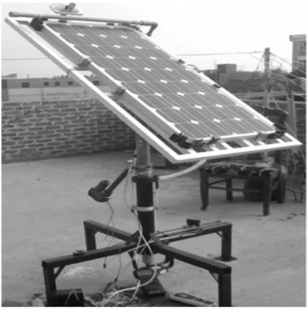
Figure 9. Proposed final H/W design.
The working of dual-axis is similar to that of the single axis but the former captures more the solar energy and is more effectively due rotating in the horizontal as well as the
vertical axes. The proposed model for dual axis tracker is shown in Figure 9.
In the latter Figure the arrangement of proposed model for dual-axis tracker mechanism, for the hardware sets up a support structure of the base platform, fitted with DC motor.
Designed with the proposed dimensions is capable to remain steadfast even in poor weather conditions, (1). This is designed with two degree of freedom to track the sun according to tilt and azimuth angle. Circular shaft, (2), which is diameter equal 3 inch it placed inside the tube of base and connected from the bottom by the DC-Geared motor, and from top by platform which supported to install the solar panel holder, O-ring for facilitation of shaft movement, (3). The DC motor controlling the horizontal movement (E-W Directions) is placed in lower end of the base (4). Actuator, of linear movement controls the vertical movement. It is supported on shaft with holder and coupled with stand frame (5). Solenoid valve, controls the water flow at cleaning times, and is installed on one lead of base (6). Water pipe, is made of plastic and has many holes with diameter 1mm toward the panel surface to spray the water after solenoid valve is active (7). Light sensor stand, of wood material is installed on the panel frame, where light sensor circuit is installed on it (8). Solar panel, (80W) of mono-crystalline type is used. It is installed on the frame platform (9). Panel platform frame, is of aluminum martial (10). Solar panel holders (11). Hardware components and mechanical materials are listed in the following table 1.
Table 1. Components and materials.
Component name Rating and material
PV panel 80W, 12V, 21.8Voc and 4.81Isc. Mono- crystalline type.
Controller PIC 18F452, SC material
DC Motor 12V, 240mA. Permanent Magnet dc motors, with gear rotary movement Liner Actuator 24V, 600mA. With gear liner movement
Water Valve Solenoid Valve, 12V-DC, electromechanically operated. Water Pipe 0.5", plastic material.
LDR 15KΩ under light, 5MΩ in dark light. SC material Light Sensor Stand Wood material, 0.5cm Think
Solar Panel Platform 60*120cm, 1200gm weight, aluminum material
Base platform Four Leads, 50cm length of a lead, highest from ground is 25cm, Mild steel material
Shaft Mild steel material
4.5. Control Software Program
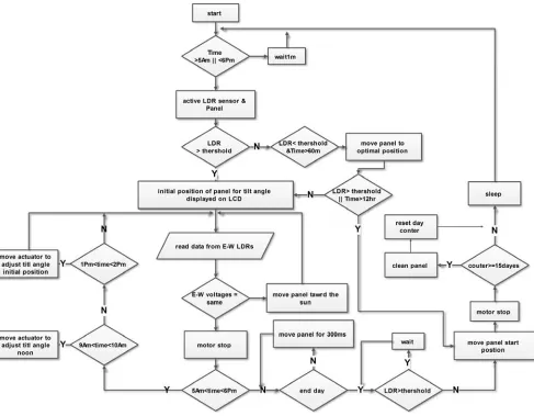
The proposed control software has been developed to determine the optimum position of the panel during day light hours, i.e., how much deviated from maximum output power. And also, developed to adjusting the tilt-angle at different seasons of year, remove accumulated dust on the surface of the solar panel every specific time period and track the panel to optimal position in cloudy day, [24]. The program for the solar tracker is written using C-Language, the Mikro C for
PIC is used. Figure 10 shows the proposed flow chart of the control software.
Figure 10. Flow chart for system.
If the output voltage value of the weather-LDR is less than the threshold value, there are two possibilities either the day reaches night or the weather is cloudy, i.e., two sensors are under shadow.
At night the PIC command makes the motor to rotate and the tracker moves to the reset position waiting for the sun from the east, consequently the PIC enters the sleeping mode to save power.
If the output voltage value of weather-LDR is more than the threshold value, the day is sunny and there are two possibilities either E-LDR is under the shadow, or W-LDR is under the shadow, and the PIC commands the motor either to rotate the panel towards east direction or towards west direction according to shadow occurring on E-W LDRs, or motor stop if shadow is not found.
If the output voltage value of the weather-LDR is less than the threshold value, there are two possibilities either the day reaches night or the weather is cloudy, i.e., two sensors are under shadow. At night the PIC command makes the motor to rotate and the tracker moves to the reset position waiting for the sun from the east, consequently the PIC enters the sleeping mode to save power.
When the weather is cloudy, the system can automatically make solar panels pointed to the best location at noon, which
makes the sun tracking system moves into a fixed solar system. The best location can be computed by PIC, which uses the light sensor technique, Limit switching and RTC. Thus, the method deals with the problem properly when the system cannot find the best location in cloudy days [25].
Summarized recent development and challenges according to respective functions of their vital components (sensitizer, substrate, electrolytes and counter electrode, semiconductor film,…) as well as their effects on photoelectric conversion efficiency [25]. When the intensity of light cannot be detected by the LDR sensors, the system can check the clock. If the time is between 6 am and 6 pm, the system is set to cloudy state. The program makes the panel to rotate to the default optimal position angle using both the limit switches and RTC, and turning off the energy-consuming parts. When weather becomes sunny, the state of the system will be changed, where the system will search for sunlight again. When the battery is discharged, the system will automatically use the spare battery.
5. Experimental Results
current and output power received from both the fixed solar panel and proposed solar tracking system at two conditions adjust in tilt-angle for a day at different times.
The obtained results from the fixed solar panel, (average values of voltage, current and output power), are 18.72 V,
2.33 A and 48.03 W respectively, where the results from proposed solar tracking system, (average values of voltage, current and output power) are 19.49 V, 3.81 A and 80.80 W respectively. The output power is collected during the period from 5:30 AM to 5:30 PM.
Table 2. Reading data from solar panel during hardware testing.
Hours fixed solar panel solar tracking panel
Volt, V Current, A Power, W Volt, V Current, A Power, W
5:30 AM 16.20 0.077 1.2474 18.10 0.10 1.8100
6:30 AM 17.30 0.140 2.4220 19.30 1.90 36.6700
7:30 AM 18.40 1.004 18.4736 19.50 3.30 64.3500
8:30 AM 18.70 1.060 19.8220 19.90 3.60 71.6400
9:30 AM 19.20 2.030 38.9760 20.50 3.65 74.8250
10:30 AM 19.50 2.200 42.9000 20.99 3.73 78.2927
11:30 AM 20.30 2.990 60.6970 21.35 3.99 85.1865
12:30 AM 20.87 3.010 62.8187 20.90 4.00 83.6000
1:30 PM 20.92 2.550 53.3460 20.50 3.78 77.4900
2:30 PM 19.60 1.900 37.2400 19.70 3.72 73.2840
3:30 PM 18.90 1.300 24.5700 19.33 3.57 69.0081
4:30 PM 17.20 0.990 17.0280 19.20 2.91 55.8720
5:30 PM 16.10 0.090 1.4490 18.30 0.40 7.3200
Figure 11 shows the comparison of electric power characteristic curves from fixed solar panel and proposed solar tracking system. It shows that proposed solar tracking system is able to receive more sunlight and consequently generate more power as compared to fixed solar panel.
Figure 11. Comparison between obtained powers from tracking proposed system vs. fixed system.
The results show that the output performance of solar array is significantly improved through optimized layout and the output power or energy is decreased when considering thermal effect [25].
There are also other factor that affects the output efficiency, dust which accumulates on the surface of the solar panel. Readings under accumulated dust are compared with the results after cleaning solar panel by the proposed cleaning system. It reveals that the average output power under the dust accumulated is 66.63W and output power on the next day after the automated cleaning is 76.50 W, the power gain improved by 18.366%.
6. Conclusion
By applying the proposed system using the PIC microcontroller which is based on an efficient solar tracking system with real time clock is developed and described. The proposed system provides a variable indication of their relative angle to the sun by comparing with predefined measured readings.
mechanical structure was very simple and reliable. The controller circuit has been designed with a minimal number of components, is integrated on two boards for simple assembly. By using this proposed system, the solar tracker is successfully maintaining a solar tracking at a sufficiently perpendicular angle toward the sun. The average obtained power increases gain over that of the fixed system was in excess of 74.1545%, during the months from March to September. and the proposed self-cleaning system improve the output power of the dual axis tracking system with 17.83%. The proposed design is achieved with low power consumption, high accuracy and low cost. The proposed constructed system can be applied in the residential area for alternative electricity generation especially for low power appliances.
References
[1] A. Canova, L. Giaccone, and F. Spertino, “Sun Tracking for Capture Improvement,” 22nd European Photovoltaic Solar Energy Conference EUPVSEC, WIP Renewable Energies, Milano. 3053- 3058, September 2007.
[2] Ammar H. Elsheikh, Swellam W. Sharshir, Mohamed Kamal Ahmed Ali, J. Shaibo, Elbager M. A. Edreis, Talaat Abdelhamid, Chun Du, Zhang Haiou, "Thin film technology for solar steam generation: Anew dawn", Solar Energy, vol. 7, pp. 561-575 (2019).
[3] S. Ozcelik, H. Prakash, andR. Challoo, "Two-Axis Solar Tracker Analysis and Control for Maximum Power Generation" Science Direct, Vol. 1, pp. 457-462, 2011. [4] Okan BİNGÖL, Ahmet ALTINTAŞ and Yusuf ÖNER
"Microcontroller Based Solar-Tracking System and its Implementation" Journal of Engineering Sciences, pp 243-248, 2006.
[5] M. A. Panait, T. Tudorache: A Simple Neural Network Solar Tracker for Optimizing Conversion Efficiency in Off-Grid Solar Generators, ICREPQ 2008, Spain.
[6] V. Thakare Vandana, Shailendra Singh, Rajkumar Thenua and Haneet Rana "Solar Tracker With Optical Source" International Journal of Electronics and Computer Science Engineering, V1N3, pp 860-864.
[7] Mayank Kumar Lokhande, "Automatic Solar Tracking System" International Journal Of Core Engineering & Management (IJCEM), Vol. 1, pp 122-133, October 2014. [8] M. R. I. Pervez, Md. Riaz Pervez, R. A. Beg, "Design,
Fabrication and Experimental Study of a Novel Two-Axis Sun Tracker" International Journal of Mechanical & Mechatronics Engineering IJMME-IJENS, Vol. 10, pp 13-18, Feb. 2010. [9] MostefaGhassoul, "Design of An Intelligent Solar Tracking
System Using PIC18F452 Micro Controller" Springer Science, pp 197-201, May 2010.
[10] M. S. Elsherbiny, Wagdy R. Anis, Ismail M. Hafez, Adel R. Mikhail, "Design Of Single-Axis And Dual-Axis Solar Tracking Systems Protected Against High Wind Speeds" International Journal of Scientific & Technology Research, Vol. 6, pp. 84-89, September 2017.
[11] Z. Ahmed, S. Sharief, "Design and Performance of Solar Tracking Photo-Voltaic System using Microcontroller" International Journal of Advanced Research in Computer Science, Vol. 8, pp 295-301, May 2017.
[12] Kais I. Abdul-lateef, "A low Cost Single-axis Sun Tracker System Using PIC Microcontroller" Diyala Journal of Engineering Sciences, Vol. 5, pp 65-78, June 2012.
[13] S. Lakeou, E. Ososanya, Ben O. Latigo, W. Mahmoud, "Design of a Low-cost Digital Controller for a Solar Tracking Photo-Voltaic (PV) Module and Wind Turbine Combination System" European Photovoltaic Solar Energy Conference, pp 2364-2368, 4-8 September, 2006, Dresden, Germany.
[14] Sobuj Kumar Ray, Md. Abul Bashar, Maruf Ahmad, Fahad Bin Sayed, "Two Ways of Rotating Freedom Solar Tracker by Using ADC of Microcontroller" Global Journal of Researches in Engineering General Engineering, Vol. 12, pp 28-34, 2012. [15] International Journal of Engineering and Technology (IJET),
volno 5 Dec 2013-Jan 2014, "solar Tracking for Maximum and Economic Energy Harvesting", Kamala J., Alex Joseph. [16] D. Venkatakrishna, E. Siva Sai, K. SreeHari, "Improved
Structure of Automatic Solar Tracking System" International Journal of Engineering Sciences &Research Technology (IJESRT), pp 295-302, July, 2015.
[17] N. Ketjoy, M. Konyu, "Study of Dust Effect on Photovoltaic Module for Photovoltaic Power Plant", Energy procedia, Volume 52, 2014, Pages 431-437.
[18] A. Syafiq A. K. Pandey N. N. Adzman Nasrudin Abd Rahim, "Advances in approaches and methods for self-cleaning of solar photovoltaic panel", solar energy jornal, vol. 16, 1 March 2018, Pages 597-619
[19] Rohit Agarwal "Concept of Mechanical Solar Tracking System" IOSR Journal of Mechanical and Civil Engineering, pp. 24-27, 2014.
[20] Gustavo Ozuna, Carlos Anaya, Diana Fig., Nun Pitalua, "Solar Tracker of Two Degrees of Freedom for Photovoltaic Solar Cell Using Fuzzy Logic" Proceedings of the World Congress on Engineering, Vol. II, WCE 2011.
[21] Asmarashid Ponniran, Ammar Hashim, Ariffuddin Joret, " Design of Low Power Single Axis Solar Tracking System regardless of motor speed", International journal of Integrated engineering, vol.3, No 2, 2011.
[22] I. Tatu and C. Alexandru, M Khalid, "A study on The Tracking Mechanisms of The Photovoltaic Modules" Fascicle of Management and Technological Engineering, pp 59-66, 2010.
[23] Weiyu Zhu, Yuanming Xu, Jun Li, Huafei Du, Lanchuan Zhang "Research on optimal solar array layout for near-space airship with thermal effect", solar energy, vol 170, pp 1-13, Aug. (2018).
[24] Gang Li, Lei Sheng, Tingyu Li, Jie Hua, Pengwei Li, Kaiying Wang "Engineering flexible dye-sensitized solar cells for portable electronics", solar energy, vol. 177, pp. 80-98 (2019). [25] Pietro Elia Campana, Louise Wästhage, Worrada Nookuea,