H i r o s h i Y o s h i h a r a • A i F u k u d a
Influence of loading point on the static bending test of wood
Received: February 20, 1998 / Accepted: May 19, 1998
A b s t r a c t We conducted three-point bending tests by changing the condition at the loading point and then exam- ined the influence of the loading point on the test data. Yellow poplar
(Liriodendron tulipfera
L.) was used for the tests. First, using loading noses with various radii, static bending tests were conducted by varying the depth/span ratios. Deflections were measured from the displacement of the cross head and at the point against the loading nose; Young's and shear moduli were obtained from the modified Timoshenko's bending equation proposed in a previous paper. Then a similar testing procedure was undertaken by inserting cushion sheets of Teflon between the specimen and the nose. After the measuring these moduli, bending strengths were measured using the loading noses and cush- ion sheets. The following results were obtained: (1) When the deflection was measured from the displacement of the cross head, the radius of the loading nose had an influence on the additional deflection when the depth/span ratio was high, causing the dependence of the shear modulus on the radius. In contrast, the radius had little influence on the measurement of Young's modulus. By placing cushion sheets between the nose and the specimen, the effect of the radius was moderated. When the deflection was measured at the point against the loading nose, the radius of the nose had little influence on the additional deflection; hence the loading nose had little influence when obtaining Young's and shear moduli. This tendency was commonly observed regardless of whet]her the cushion sheets were in place. (2) When the specimen had a high depth/span ratio, the bend-H. Yoshihara (g~)
Faculty of Science and Engineering, Shimane University, Matsue 690-8504, Japan
Tel. +81-852-32-6508; Fax +81-852-32-6123 e-mail: [email protected] Ai Fukuda
Faculty of Agriculture, Shimane University, Matsue 690-8504, Japan
Part of this paper was presented at the 48th annual meeting of the Japan Wood Research Society, Shizuoka, April 1998
ing strength increased with the increase in the radius of the loading nose. However, the influence of the radius was small when the specimen had a low depth/span ratio. There was no significant effect of the cushion sheets used here on the measurement of bending strength.
Key words Bending test • Loading nose. Cushion material • Elastic modulus • Bending strength
Introduction
To evaluate the static deformation and strength properties of wood, three-point bending tests are often conducted be- cause of their simplicity and the many occasions where structural materials are subjected to a bending load in prac- tical applications. However, the bending tests often seem to be undertaken without considering the loading condition carefully. We think that this negligence occurs because of the simplicity of the test itself. According to several studies on advanced materials, such as carbon fiber-reinforced plas- tics (CFRP) and glass fiber-reinforced plastics (GFRP), the loading condition has a serious influence on the bending properties. 12
We thought that the influence of the loading conditions should be considered more carefully in the bending tests of wood. Therefore, we conducted some bending tests under various loading conditions and examined the influence of the loading conditions on the measurement of bending properties.
Experiment
Specimens
Measurement of elastic moduli using various loading noses and cushion materials
Beam specimens were cut to the dimensions of 600mm (longitudinal direction) × 20ram (radial direction) × 2 0 m m (tangential direction) for the measurement of Young's and shear moduli. To examine the influence of the stress concentration near the loading point, the radii of loading noses r were varied as 5, 10, 15, 20, 25, 30, 50, 70, and 90 mm. The noses whose radii were smaller than 30 m m had a half-cylindrical shape. When the radius was larger than 50mm, it was difficult to prepare the half-cylindrical nose.
Thus noses with radii of 50, 70, and 90mm had the shapes illustrated in Fig. 1. Using these noses, static bending tests were conducted under spans varying from 80 to 480mm at intervals of 100mm. The vertical load, whose velocity was 5 mm/min, was applied to the center of the longitudinal- radial (LR) surface, and the deflections were measured by the displacement of the cross head and by the dial gauge set below the center of the specimen. These measurement points correspond to points A and B in Fig. 2. From the linear segment of the load-deflection diagram, the bending Young's modulus (Es), dependent on the depth/span ratio, was obtained by the elementary bending theory as:
0
k
¢
k
Fig. 1. Loading noses whose radii are larger than 50mm
0
10
30
10
Fig. 2. Bending-test equipment. r, radius of loading nose. A, B, measured points of deflections
A
Support
Load P
Loading nose
Dial g a g e
S p e c i m e n
475
E s -
[3 A P 4bh 3 A y
bending strength was evaluated by the equation obtained (1) from the elementary bending theory as follows:
where l, b, and h are the span, breadth, and depth of the beam, respectively, A P is the load increment, and A y is the deflection increment corresponding to A P . As mentioned above, A y was measured from the displacement of the cross head and by the dial gauge. We defined Es as the "apparent Young's modulus" here.
The Young's and shear moduli, E and G, were obtained by regressing the Es - h/l relation into the modified Timoshenko's equation proposed in a previous paper] This equation is written as follows:
3Pj
-
(3)
2bh 2
where Pb is the load at the occurrence of breakage. For a loading nose radius of 15mm, the bending strengths were measured by placing the Teflon sheets between the speci- men and the nose. Five specimens were used for each test condition.
1 _ 1 + 1 . 1 . 2 + a - 7 . (2)
E s E G
where a is a coefficient) The value of a was determined by the flexural vibration tests mentioned below.
A similar testing procedure was followed after placing cushion sheets between the specimen and the loading nose. The cushion material was Teflon of 2ram thickness. The numbers of sheets varied, and the effect of the cushion on Young's and shear moduli was examined.
Flexural vibration tests
Independent of the static bending tests, free-free flexural vibration tests were conducted using the following proce- dure. The test beam was suspended by two threads at the nodal positions for free-free vibration corresponding to its resonance mode. The specimen was excited at the top of the thickness at one end by a hammer. The resonance frequen- cies, whose mode was from first to fourth, were measured by the fast frequency transform (FFT) digital signal analyzer, and Young's and shear moduli were obtained from the Timoshenko-Goens-Hearmon method, the details of which have been described in several previous papers. 4 The Young's and shear moduli obtained from the vibration tests were compared with the moduli obtained by static bending tests.
Measurement of the bending strengths using various loading noses and cushion materials
To measure bending strength using various loading noses and cushion materials we prepared the specimens from the same flitch from which the specimens were obtained for measuring the elastic moduli. The specimens had a cross section of 10ram (radial direction) × 10ram (tangential direction); and the spans were 80, 140, and 250mm. The bending strengths were measured by varying the loading noses in a manner similar to that for measuring the elastic moduli. We verified that the loading speed did not seriously influence the value of bending strength in the range of 2- 10mm/min. Here, the vertical load was applied to the center of the L R surface at the cross head speed of 10mm/min. The
Results and discussion
Young's and shear moduli obtained by the static bending tests
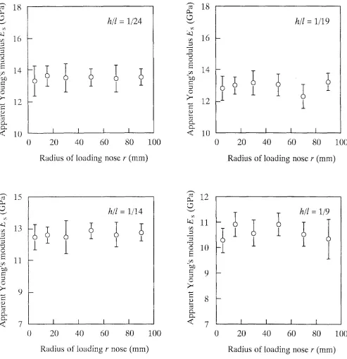
Figures 3 and 4 show the apparent Young's modulus (Es) corresponding to the radius of loading nose (r) when the deflection was measured from the displacement of the cross head and from that of the dial-gauge rod, respectively. Fig- ure 3 indicates that when the deflection was measured at the loading point the apparent Young's modulus was small, in the small r range, but was significant at a high depth/span ratio. In contrast, the dependence of Es on the radius was small when the deflection was measured at a point against a loading nose.
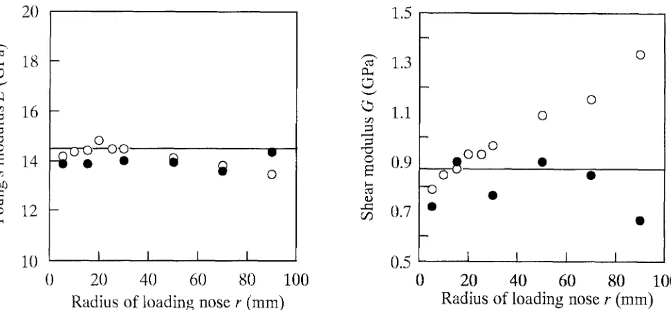
Figure 5 shows Young's modulus (E) and the shear modulus (G) obtained by regressing the E s - h / l relation into Eq. (2) corresponding to the radius of the loading nose (r). For the data obtained by measuring the deflection from the displacement of the cross head, the coefficient a was deter- mined to be 20 by referring to the flexural vibration testing results - Ev = 14.4GPa and Gv = 0.88GPa - and the static bending test data of r = 15mm, and the value of a - h/!
ranged from 0.84 to 2.25. Similarly, a was determined to be 2.0 for the data obtained by measuring the deflection at the point against the loading nose, and the value of a • h/l
ranged from 0.08 to 0.23. The radius of the nose had little influence on the value of Young's modulus, regardless of the points the deflection measured, because of the small effect of the nose on the low depth/span ratio range. Hence, r does not have to be considered seriously when measuring Young's modulus. As for the shear modulus, the influence of the radius was significant when the deflection was measured from the displacement of the cross head. This phenomenon occurred because of the dependence of the apparent Young's modulus on the radius of loading nose in the high depth/span range. In contrast, the shear modulus was not seriously influenced by r when the deflection was measured at a point against the loading nose.
O
~t3
©
k-.. ¢3.
<
18
16
14
12
10
h/l
= 1/24
I
0I I I
20
40
60
80
100
Radius of loading nose r ( m m )
E
¢) ¢J
<
18
16
14
-12
10
0
h/l
= 1 / 1 9I I I
20
40
60
80
100
Radius of loading nose r ( m m )
15
13
7/3E
11
>"
9
¢3.
7
h/l
=1/14
I I I I
0
20
40
60
80
100
Radius of loading r nose (ram)
Fig, 3. Influence of the radius of the loading nose on the a p p a r e n t Y o u n g ' s m o d u l u s corresponding to t h e d e p t h / s p a n ratio w h e n t h e de- flection was m e a s u r e d f r o m the displacement of t h e cross h e a d (point
12
11
r,t?1 0 O
~ 3
= 9 ©
8
< 7 I
0 2 0
h/1
= 1 / 91
I I I
40
60
80
100
R a d i u s o f l o a d i n g n o s e r ( m m )
,'d
>-,
D.
<
18
16
h/l
= 1/24
1 4 i I ~
I
~
(T)
_[
;
1
12
10
0
I
I
I
I
20
40
60
80
100
Radius of loading nose
r ( m m )
18
16
14
©
>" 12
D.
< 10
h/l
= 1 / 1 9
0
m
-
I
I
I
I
I
2 0
4 0
6 0
8 0
1 0 0
R a d i u s o f l o a d i n g n o s e r ( m m )
O
E
c / ?
©
>.
.,..a
C2.
<
15
13
11
9 -
7
0
h/l
= 1/14
12
©
©
~a0
>.
D~ D~
<
100
11
10
_
_
;
-1
1
1
[
I
I
I
I
7
I
I
I
I
20
40
60
80
0
20
40
60
80
1 {}{}
R a d i u s o f l o a d i n g r n o s e ( m m )
R a d i u s o f l o a d i n g n o s e r ( r a m )
2O
1.5
--:¢
18
©
:~ 16
" o O
E 14
12
°
ii
il
o
1.3
1.1
~0"-O
o
0.9
,x: ~0
_ 0 0 °
O
O O
-O •
- 0 . 7 •
10
I ~ ~ t 0.5 I I I0
20
40
60
80
100
0
20
40
60
80
100
Radius of loading nose r (mm)
Radius of loading nose r (ram)
Fig. 5. Influence of the radius of the loading nose on Young's and shear moduli calculated from the modified Timoshenko's theory of bending.
Open and solid circles were obtained from measurements of deflections at points A and B, shown as in Fig. 2, respectively
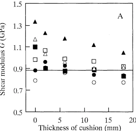
the effect of the nose shape was moderated by the presence of the cushions, and the shear moduli obtained were rather consistent. When the nose had a radius of 5 mm or 90mm, howeverl the cushion had no effect on the measurement of the shear modulus. Hence, when the deflection is to be measured at the loading point, we recommend that cushion materials be placed between the specimen and the loading nose with an intermediate radius. In contrast, when the deflection is to be measured at a point against the loading point, the Young's and shear moduli can be measured with or without the cushions.
The measurement method of deflection is described in detail in ASTM D143-1994, 5 whereas it is not defined in JIS Z2101-19946 or ISO 3349-1975. 7 Hence, on several occasions the deflection has been measured from the displacement of the cross head. Because of the consistent values for elastic moduli obtained by our method, we be- lieve that the deflection should not be measured from the displacement of the cross head when determining elastic moduli.
Bending strength
For every specimen tested here, the failure began at the bottom, even when the specimen had a depth/span ratio of 1 : 8; it was not failed by horizontal shear.
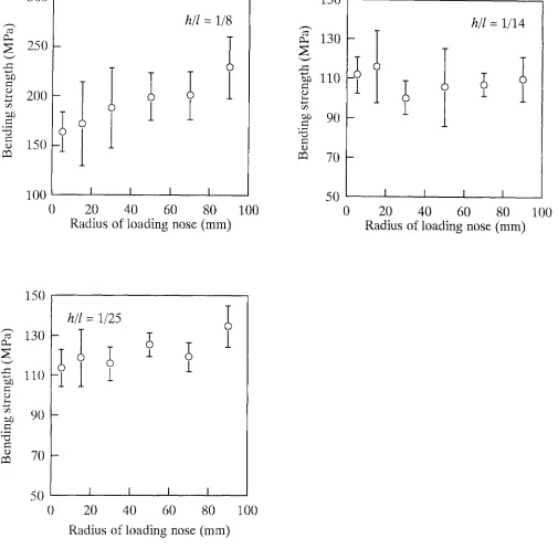
Figure 7 shows the bending strengths corresponding to the radii of the loading noses. The results of bending tests of FRP suggests that the radius of the loading nose has a significant influence on the bending strength even when the specimen has a low depth/span ratio) The radius had an influence on measurement of the bending strength when the
depth/span ratio was 1 : 8. When this ratio was low enough, however, the influence of the radius on bending strength was small.
Figure 8 shows the influence of cushions on the measure- ment of bending strength. Because the cushion sheets had an effect on the additional deflection for the specimens with high depth/span ratios, we expected that their effect would be significant for the bending strengths of the specimen with a depth/span ratio of 1:8. However, the obtained bending strengths were not influenced by placing the cushions. In this experiment, we used Teflon as the cushion. In the bend- ing tests conducted by Hojo and colleagues, however, the effects of the cushion were different depending on the ma- terial used. 2 We suggest that the efficiency of several mate- rials be examined relative to measurements of bending strength.
Conclusion
We conducted some bending tests of wood under various loading conditions and examined the influence of the load- ing conditions on the bending properties. The following results were obtained:
20
18
k4
16
: 0
= 12
O10
A
t
I
I
I
I
{}
5
10
15
T h i c k n e s s of cushion (mm)
20
cD
, . . i l
,.ca c/?
1.5
1.3
1.1
0.9
0.7
0.5
A[]
k - ,
O
A
II
[]
O O
I
I
I
I
0
5
10
15
T h i c k n e s s of cushion (mm)
20
20
B
~: 18
(9
16
O
=
12
O
>-,
1(}
I
I
I
I
0
5
10
15
20
T h i c k n e s s of cushion (mm)
Fig. 6. Effect of cushions on Young's and shear moduli. Open circles, solid circles, open squares, solid squares, open triangles, and solid tri- angles, radius of loading nose r = 5, 15, 30, 50, 70, and 90ram, respec-
1.5
1.3
©
1.1
,-¢j
o
0.9
E
~z
0.7
OqB
- B m
- 7 i
i
0
i
0.5 I
I
I
I
I
0
5
10
15
20
Thickness of cushion (ram)
: 8
o ~ - ~
3 0 0
250
200
150
1
h/l
: 1/8
; 1
l
100
I
I
I
I
{}
20
40
60
80
R a d i u s o f l o a d i n g n o s e ( m m )
100
150
130
,xa
:8
110
=8 90
"0
m
70
50
h/l
= 1/14
I I I I
0
20
40
60
80
R a d i u s o f l o a d i n g n o s e
(mm)
100
150
h/1
= 1/25
~ 110
I
I
o
:8
90 -
, ~ . ~
m
7 0 -
J.
1
1
50
I
I
I
I
0
20
40
60
80
100
R a d i u s o f l o a d i n g n o s e ( m m )
300
150
250
200
150
m
h/l
= 1/8
[
I
l
I
J.
100
i
I
I
0
5
10
15
20
Thickness of cushion (ram)
.s:Z o
"'d
130
110
90
70
50
Fig, 8. Effect of cushions on the bending strength. See Fig. 3 for further explanations
;1
h/l
= 1/14
±
I i I
0
5
10
15
20
Thickness of cushion (mm)
n o s e h a d little i n f l u e n c e o n t h e a d d i t i o n a l d e f l e c t i o n ; h e n c e , t h e i n f l u e n c e of t h e l o a d i n g n o s e was s m a l l w h e n o b t a i n i n g t h e Y o u n g ' s a n d s h e a r m o d u l i . T h i s t e n d e n c y was c o m - m o n l y o b s e r v e d r e g a r d l e s s o f w h e t h e r t h e c u s h i o n s h e e t s w e r e in place.
2. W h e n t h e s p e c i m e n h a d a h i g h d e p t h / s p a n ratio, t h e b e n d i n g s t r e n g t h i n c r e a s e d w i t h t h e i n c r e a s e in t h e r a d i u s o f t h e l o a d i n g n o s e . T h e i n f l u e n c e of t h e r a d i u s was s m a l l w h e n t h e s p e c i m e n h a d a l o w d e p t h / s p a n ratio. T h e e f f e c t of t h e c u s h i o n s h e e t s u s e d h e r e o n t h e m e a s u r e m e n t of b e n d - ing s t r e n g t h was n o t m a r k e d .
Acknowledgments
We thank Prof. Masamitsu Ohta of The University of Tokyo and Dr. Yoshitaka Kubojima, a researcher at the Forest and Forest Products Research Institute, for their help in conducting our experiment.References
1. Uemura M (1981) Problems and designing the standards of me- chanical tests of fiber reinforced plastics II (in Japanese). Trans Jpn Soc Comp Mater 7(2):74-81
2. Hojo M, Noguchi Y, Furue H, Matsui J (1987) Test method for flexural properties of unidirectional laminates reinforced with 4 GPa-class carbon fibers (in Japanese). Reinforced Plast 33:2-11 3. Yoshihara H, Kubojima Y, Nagaoka K, Ohta M (1998) Measure-
ment of the shear modulus of wood by static bending tests. J Wood Sci 44:15-20
4. Hearmon RFS (1958) The influence of shear and rotatory inertia on the free flexural vibration of wooden beams. Br J Appl Phys 9:381- 388
5. ASTM D143-1994: Standard methods of testing small clear speci- mens of timber
6. JIS Z2101-1994: Methods of test for woods