https://dx.doi.org/10.24001/ijaems.3.8.8 ISSN: 2454-1311
A variable gain PI to improve the performances
of a unified power flow controller system
M. Sekour, M. Mankour, Kada Hartani
Laboratory of Electrotechnical Engineering, University Tahar Moulay of Saida, Algeria
Abstract— The instability problems in the electrical supply networks have had a great impact on recent research studies on modern devices. The unified power flow controller (UPFC) is one of the various FACTS (Flexible Alternative Current Transmission Sys-tems) devices that allow the electrical supply networks to be stable with a strong effectiveness. In this paper, the performances of such a device using both a classical PI and a variable gains PI controllers are examined. For this instance, the compensator is first stabilized before trying to stabilize the network. A series of comparative simulation tests have been undertaken for both regulators and analyzed. From the obtained results it is clearly shown that when the system is equipped with the variable gain PI regulator, the performance are much better.
Keywords— Improvement, Unified power flow controller (UPFC), Variable gain PI controller
I. INTRODUCTION
The demand of efficient and high quality power is
continuously growing in the world of electricity. Today’s
power systems are highly complex and require suitable design of new effective and reliable devices in deregulated electric power industry for flexible power flow control. In the late 1980s, the Electric Power Research Institute (EPRI) introduced a new approach to solve the problem of designing, controlling and operating power systems: the proposed concept is known as Flexible AC Transmission Systems (FACTS) [1, 2, 3, 4]. It is reckoned conceptually a target for long term development to offer new opportunities for controlling power in addition to enhance the capacity of present as well as new lines [5, 6]. in the coming decades. Its main objectives are to increase power transmission capability, voltage control, voltage stability enhancement and power system stability improvement. Its first concept was introduced by N.G.Hingorani in April 19, 1988. Since then different kind of FACTS controllers have been recommended. Controllers are based on voltage source converters and includes devices such as Static Compensators (SVC), static Synchronous Compensators (STATCOM), Thyristor Controlled Series Compensators (TCSC), Static Synchronous Series Compensators (SSSC)
and Unified Power Flow Controllers (UPFC).Among them UPFC is the most versatile and efficient device which was introduced in 1991. In , the transmitted power can be controlled by changing three parameters namely transmission magnitude voltage, impedance and phase angle. Unified Power Flow Controller (UPFC) is the most promising version of FACTS devices as it serves to control simultaneously all three parameters (voltage, impedance and phase angle) at the same time. Therefore it is chosen as the focus of investigation. For the last few years, the focus of research in the FACTS area is mainly on UPFC. Many researchers have proposed different approaches of installing UPFC in power systems [3, 4, 8, 11]. The concepts of characteristics have been broadly reported in the literature [5, 12].
II. OPERATINGPRINCIPLEOFUPFC
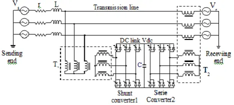
The UPFC is connected in a simplified transmission system as shown in Fig 1. It's installed at the end of the transmission line to which it's connected through the two transformers T1 and T2 [6]. In Fig.1, the voltages and represent respectively the sources of three-phase sinusoidal voltage of the transmission line departure and arrival. The UPFC consists of two inverters controlled PWM (Pulse Width Modulation) placed back-to-back and connected to a capacitor [8, 9]. The series inverter provides the compensation voltage across the transformer series, while the parallel or shunt inverter provides or absorbs reactive power and active power demanded by the series inverter and regulates the voltage at the capacitor level. The active and reactive power are generated and absorbed independently by each inverter [11].
https://dx.doi.org/10.24001/ijaems.3.8.8 ISSN: 2454-1311
III. MATHEMATICALMODELINGOFUPFC
The modeling process has enabled us to obtain equations for the various parameters of the different parts of the system and allowed us to have according to park a suitable model, where we can show the parameters of such an appropriate setting. The simplified circuit of the control system and UPFC compensation is shown in Fig.2.
Fig.2: Equivalent circuit of the UPFC
The dynamic equations of the UPFC are divided into three systems of equations: equations of the series branch, equations of the parallel branch and those of the circuit of DC current.
By applying Kirchhoff's laws we get the following equations for each branch.
3.1. MODELING OF SERIES BRANCH
It is supposed that the inverters series and shunt are ideal controllable voltage sources. Thus, from Fig 2, and by applying the Park transformation to the source voltages Vs and Vr we get the following equation:
sd cd rd
sd sq
sd V V V
L i L r ωi dt
di 1
(1)
sq cq rq
sq sd sq V V V L i L r ωi dt di
1 (2)
3.2. Modeling of the UPFC Continues Branch
Based on the principle of power balance and neglecting the losses of the converters, the voltage is obtained from the following equation:
pd pd pq pq cd rd cq rq
dc
dc V i V i V i V i
CV dt dV 2 3 (3)
3.3. Adjustment of the UPFC
The active and reactive powersP and Q are given by the equations:
Vrd(isd ipd) Vrq(isq ipq)
P
2 3
(4)
The reference power and reactive P*and Q* of the desired real powers P and Q are used as input to the control system of UPFC. From equation (7) the reference currents i*sd and i*sq can be calculated as follows.
2 2
3 2 rq rd sq sd sd V V V Q V P *
i
2 2
3 2 rq rd sd sq
sq V V
V Q V P *
i (6)
These reference values are then compared with actual line currents from the receiver. The outputs of the editors provide the current values of control voltages Vsd and Vsq. The goal is to have active and reactive power at the finish line (Receiving End) identical to those instructions (P*,Q*) by forcing the line currents (i*sq,i*sq) to monitor
properly their references. The reference currents calculated (6) compared to the actual line currents and after a correction to the current one ends control voltages (UPFC series) and Vcq representing the reference voltage
control circuit pulse modulation wide (PMW) of the inverter. Fig.3 represents the series UPFC control.
Fig.3: Block Diagram of the UPFC Control (Serie)
IV. DECOUPLED PI CONTROLLER
According to the system of equation (5) one can have the system contains a coupling between the reactive and active current. The interaction between current loops
caused by the coupling term (ω) Fig.3. This explains the
deviation of reactive power with respect to the reference. To reduce the interaction between the active and reactive power, a decoupling of the two current loops is needed.
The function of decoupling is to remove the product ωLiqs
and controller along the axis and adding the product term
ωLids and the controller along the axis q. There is various
adjustment techniques well suited to the PI controller [8, 9]. So according to the method of Ziegler-Nichols, the critical gain Kpc and the period Tc of the oscillations is
https://dx.doi.org/10.24001/ijaems.3.8.8 ISSN: 2454-1311
Table.1. Ziegler–Nichols method
V. VGPI CONTROLLER STRUCTURE
The use of controllers to control the UPFC is often characterized by an overshoot in tracking mode and a poor disturbance rejection. This is mainly caused by the fact that the gains of the controller cannot be set to solve the over shoot and disturbance rejection problems simultaneously [10]. Overshoot elimination setting will cause a poor disturbance rejection, and rapid disturbance rejection setting will cause important overshoot or even instability in the system. To overcome this problem, we propose the use of variable gains controllers.
A variable gain (VGPI) controller is a generalization of a classical controller where the proportional and integrator gains vary along a tuning curve as given by Fig.4 and Fig.5. Each gain of the proposed controller has four tuning parameters [9, 11]:
• Gain initial value or start up setting which allows overshoot elimination.
• Gain final value or steady state mode setting which allows rapid disturbance rejection.
• Gain transient mode function which is a polynomial curve that joins the gain initial value to the gain final value Fig .4.
• Saturation time which is the time at which the gain
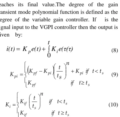
reaches its final value.The degree of the gain transient mode polynomial function is defined as the degree of the variable gain controller. If is the signal input to the VGPI controller then the output is given by:
K
e(t)
t
K
e(
τ(τ)
i(t)
p i0
(8)
s pf s pi pi pf pi t if t Kt if t K n s t t K K
K (9)
s if s s if i t t if K t if t n
t t K
K (10)
Fig .4: VGPI Tuning Curve Fig .5: VGPI controller
Where Kpi and Kpf are the initial and final value of the
proportional gain Kp, and Kif is the final value of the
integrator gain Ki. The initial value of Ki is taken to be
zero. It is noted that a classical PI controller is a VGPI controller of degree zero.
The VGPI unit step response is given by:
VI.
s s if pf s s f pi pf pi t if t t n n t K K t if t n t t t n i K K K K i(t) 1 1(11)
If t >TS (transient region), the classical PI unit step
response is a linear curve beginning at Kpf and finishing at
Kpf+TsKif, whereas the VGPI unit step response (n≠0)
varies along a polynomial curve of degree n+1 beginning at Kpi and finishing at (Kpf+TsKif) /( n+1).If t ≥TS
(permanent region), the unit step responses of a PI and a VGPI controller are both linear with slope Kif. From these
results, one can say that a VGPI controller has the same properties than a classical PI controller in the permanent region with damped step response in the transient region. A VGPI controller could then be used to replace a PI controller when we need to solve the load disturbance rejection and overshoot problems simultaneously.
Control
Type Kp Ti Td
https://dx.doi.org/10.24001/ijaems.3.8.8 ISSN: 2454-1311
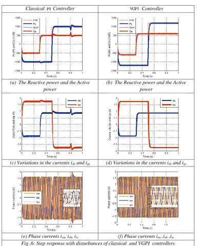
To assess the sensitivity to disturbances of the controllers we introduced at t= 0.8s a disturbance of amplitude equal
to ω/5 and a duration of 0.2s.Fig.6 (a, c, e) illustrates the
behaviour of active and reactive power and current, where we see that the control system has a fast dynamic response to the forces reach their steady states after a change in the reference values. We also note the presence of the interaction between the two components. These influences are caused by the inverter is unable to produce continuous signals needed by the decoupling, thus increasing the error in the PID controllers. The results given by fig.6 (b, d, f) show excellent performance in regulation for the VGPI controller with very good.
are excellent for the VGPI controller which also provides better performance in terms of power and time disturbance rejection.
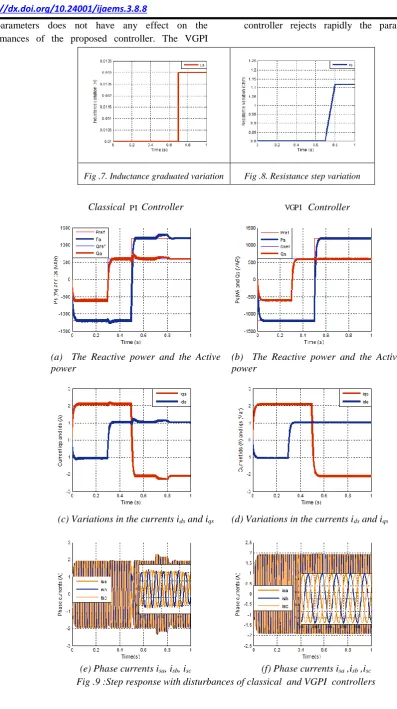
VII. ROBUSTNESS
In order to verify the robustness of VGPI regulator under UPFC parameters variations, we have simulated the system with inductance step variation at t=0.7s and resistance graduated variation between (t=0.7s and 0.8s) fig.7, fig.8. Fig.9 (b, d, f) shows the responses powers and currents in the test of robustness when the transmission line parameters are changed in a relative large range. The results indicate that the VGPI regulator Classical Controller Controller
(a) The Reactive power and the Active power
(b) The Reactive power and the Active power
(c) Variations in the currents ids and iqs (d) Variations in the currents ids and iqs
(e) Phase currents isa, isb, isc (f) Phase currents isa ,isb ,isc
Fig .6: Step response with disturbances of classical and VGPI controllers
https://dx.doi.org/10.24001/ijaems.3.8.8 ISSN: 2454-1311
the parameters does not have any effect on the performances of the proposed controller. The VGPI
controller rejects rapidly the parameters disturbance
Fig .7. Inductance graduated variation Fig .8. Resistance step variation
Classical Controller Controller
(a) The Reactive power and the Active power
(b) The Reactive power and the Active power
(c) Variations in the currents ids and iqs (d) Variations in the currents ids and iqs
(e) Phase currents isa, isb, isc (f) Phase currents isa ,isb ,isc
Fig .9 :Step response with disturbances of classical and VGPI controllers
https://dx.doi.org/10.24001/ijaems.3.8.8 ISSN: 2454-1311
VIII.
CONCLUSION
The performance of the UPFC under classical and VGPI method control was investigated. A UPFC located at the middle of the transmission line was modelled realistically by transforming its variables into a rotating synchronous reference frame. The developed control concept shows an excellent dynamic behaviour and behaves robust to parameter changes of the power system. In conclusion it seems that classical PI controllers could be transformed to high performance robust controllers just by varying their gains. Our perspective is to develop a variable gain Fuzzy Logic controller for power control.
APPENDIX
Table.II.System parameters
Parameter name Symbol Value Unit
Voltage of network Vs 220 Volt
Voltage of loads Vr 220 Volt
DC link voltage Vdc 280 Volt
Frequency f 50 Hz
Capacitor C 2000 F
Resistance of the line
(serie) rs 0.8
Inductive reactance of the
line (serie) Ls 10 mH
Resistance of the line
(shunt) rp 0.4
Inductive reactance of the
line (shunt) Lp 10 mH
REFERENCES
[1] K.Narendra, K. Parthasarathy Identification and control of dynamical systems using neural networks, IEEE Trans. Neural Networks, Vol 1, pp 4-27,(1990).[2] F-C.Chen, Back propagation neural networks for nonlinear self-tuning adaptive control, IEEE Control System Magazine, Special Issue on Neural Networks for control - pp 45-48,(1990). [3] F-C.Chen, Adaptive control of a class of nonlinear
discrete-time systems using neural networks,IEEE Trans. Automatic Control, Vol 40, nº 7, pp 791-801, (1995).
[4] L. Jin et al, Adaptive control of discrete time nonlinear system using recurrent neural networks, IEE Proc. Control Theory Applications, Vol 141, nº 3, (1994).
[6] J. Henriques, A. Dourado,,A Hybrid Neural-Decoupling Pole Placement Controller and its Application , accepted for presentation in ECC99 - 5rd
European Control Conference, Karlsruhe, Germany, 31 August – 03 September 1999.
[7] S. Zebirate, A. Chaker, Commande hybride du système UPFC, RS série RIGE. Volume 7- n° 1-2/, pages 75 à 104, (2004).
[8] Sheng-Huei Lee ,Chia-Chi Chu.,Power Flow Models of Unified Power Flow Controllers in Various Operating Modes. IEEE Trans. Power Elect. 0-7803-8110-6/03, (2003).
[9] H. Fujita,Y. Watanabe ,H. Akagi, Dynamic Control and Performance of a Unified Power Flow Controller for Stabilizing an AC Transmission System, IEEE Trans. Power Elect. 21(4): 1013-1020, (2006). [10] A.Miloudi, Al Radadi, A. Draou,, A Variable Gain
PI Controller Used for Speed Control of a Direct Torque Neuro Fuzzy Controlled Induction Machine Drive, Turkish Journal of Electrical Engineering, VOL.15, NO.1, pp. 37-49, (2007).
[11] M.Sekour,A.Chaker,M. Benyahya,S. Zeberate , Deffect of instability in supplay network and improvementwith UPFC and VGPI, AMSE Journal, Association for the Advancement of modeling & Simulation, USTHB, Alger Algeria july 02-05, (2007).