DESIGN & DEVELOPMENT OF IMPROVED PLASTIC BAFFLE FOR COST
EFFECTIVENESS
VARSHA DHANGAR, PG Student, JSPM, RSSCOE,
DR. AVINASH BADADHE, Guide, RSCOE, Tathawade, Pune
ABSTRACT:
The current trend NVH plays an important role while designing the BIW of automobile vehicle. Acoustic baffle is one of the important parts of a vehicle which helps in reducing the NVH of vehicle. This report gives the design of baffle for section 8 of lower end of A pillar. Previously baffle was made by pressing the expandable foam material between the two metal plates. These metal plates are replaced by a plastic carries which is made up of polyamide. These plastic carries are manufactured by using the injection molding & after that expandable foam, made of ethylene/vinyl-acetate copolymers (EVA) is overmold on the plastic carrier. Selection of expandable foam material various testing need to be carried out like, temperature storage stability (before & after expansion), adhesion, mechanical behavior, expansion behavior, chemical &corrosion stability. Also snapping feature design provides the advantage of using the same baffle for both right hand side & left hand side of pillar. By using this baffle noise level can be reduced up to 15db. When BIW goes into the electro coat baking oven, the sealing material is being heated to a temperature in the range of the activation temperature. The heat expandable material is sealing the peripheral gap between the carrier and the inner side of the cavity walls. After the expansion of foam NVH test will be carried out at vehicle level to compare the results. The use of expandable foam baffles with plastic material as a carrier replaces the use of metal carrier & thereby reducing the complexity, cost, reduced weight & reduced assembly operations. As the metal part is avoided there is no possibility of rusting of pillars or baffle. Also the main advantage is, the injection molding process gives the consistency in the part & therefore the foam reaches corner sealing with guided expansion.
KEYWORDS: Design of baffle, Prototyping, NVH testing
I. INTRODUCTION: A. BACKGROUND:
Previously baffle was made by comprising expandable
sealing by fitting it to the structured member [1]. With modern techniques baffles were designed in correspondence to the cross sectional member of cavity of hollow structure & by this wastage of material was reduced to certain extent [2].
Modern vehicle concepts and structural designs of vehicles have a plurality of cavities which have to be sealed in order to prevent the ingress of moisture and contaminants, since the latter can result in corrosion from the inside on the corresponding body parts. This applies to modern self-supporting body constructions in which a heavy frame construction is replaced by so-called “space frames”. With the latter, use is made of a lightweight, structurally solid chassis made of prefabricated hollow sections. Such constructions have, depending upon the specific system, a number of cavities which have to be sealed against the penetration of moisture and contaminants. These cavities include the upwardly extending A, B and C Pillars supporting the roof structure, the roof rail, portions of the fenders, or the sill. In addition, these cavities transmit airborne sound in the form of unpleasant vehicle running noises and Wind noises, therefore Such sealing measures also serve to reduce the noises and therefore to enhance the comfort of traveling in the vehicle. During the assembly of the car, these frame parts and body parts containing cavities are prefabricated from half-shell components which were joined at a later time by welding and/ or adhesive bonding so as to form the closed hollow section. With such a type of construction the cavity in the early body in White (“body shop”) state of a vehicle body is accordingly easily accessible, so that sealing and acoustically damping baffle parts (sometimes referred to as “pillar fillers” or “cavity filler inserts”) can be fixed in this early phase of body construction by mechanical hanging, by insertion into appropriate holding devices, bores or by Welding to the cavity walls [3].
between the carrier and the walls of the cavity. Typically, the sealing material is activated (thermally or chemically) after insertion into the cavity so that the sealing material forms a seal with the walls of the cavity [3].
Certain design factors can affect the performance of a baffle. For example, a baffle can include a rigid carrier that supports a layer of expanding foam. The weight and thickness of the rigid carrier can affect how the baffle reacts to various noise and vibration frequencies. Unfortunately, certain baffle designs that include a rigid carrier cannot be modified without expensive changes in tooling and manufacturing. Therefore, it can be time consuming and expensive to tailor a baffle to a particular application, or to change the design to meet certain customer requirements.
II. PROBLEM STATEMENT AND OBJECTIVES: A. A. PROBLEM STATEMENT:
To design and manufacture the acoustic plastic baffle for section 8 of A pillar by using injection molding to reduce the wastage of foam material & ultimately reduce the cost. Instead of using metal nut bolts checking the feasibility of plastic fastening feature.
B. OBJECTIVES:
1) To reduce the vibration and avoid the entry of
contaminants
2) To provide the solution of plastic baffles for currently
using Metal baffles.
3) To avoid the wastage of foam material by injection
molding
4) To avoid the use nuts and bolts for fastening to structure. 5) To Reduce Cost
III. METHODOLOGY: A. DESIGN CALCULATION:
For fitting the metal baffle to the pillar customer is using M8 bolt.
Hence from this we have calculated the load which is acting on the bolt.
d= 8mm dc= 0.8dmm
Syt (Plain Carbon Steel 30C8)= 450 N/mm2
Factorof safety= 5 Strength of bolt in tension
Strength of bolt in shear
As tensile load acting bolt is more than the shear load. Hence tensile load need to be used for further calculation.
Section modulus calculations
Fig .1 Hollow rectangular beam section bo= 122.2mm
bi= 118.2mm do= 70.9mm di= 66.9mm
(Fig.1 shows dimensions of the A pillar Section 8.) Moment of inertia in X-direction
Section modulus in X-direction
Moment of inertia in Y-direction
For selection of snapping feature & material we need to calculate the Tensile stress & bending moment developed in the structure.
Bending moment of beam in X-direction
As per DSR standard given by customer, door trims are tested against the load of 1500N in X-direction to check the load carrying capacity of door trim.
Stress induced in X-direction
As bolts are acting load in Y-direction, hence tensile load (P= ) is used for calculating the bending moment & stress in Y-direction.
Bending Moment @ A=0
Bending Moment @ C= 4204.23X23.3= 97958.559N Bending Moment @ D= 4204.23 X (23.3+16) – 2859.29X16 = 165226.239 – 45748.64
= 119477.599 N-mm
Bending moment @ point D has maximum value, hence using this force for calculating stress induced in Y-direction.
Total stress induced in structure,
B. MATERIAL SELECTION: 1. PLASTIC CARRIER:
The rigid support plate is made of polyamide or sheet metal selected from steel, galvanized steel, aluminum or aluminum alloys. The carrier is preferably made from a thermoplastic material with a melting point above the activation temperature range. Preferred thermoplastics are polyamides, polyimides, polyoxypropylene or polyethylene terephthalate, most preferably the carrier is made of polyamide. The polyamide for making the carrier and/or the rigid support plate may contain fibers and/ or inorganic fillers. Also polyamides have good adhesion characteristics which can hold the foam material in place. Polyamides are the group of thermoplastic polymers containing amide groups in the main chain. They are popularly known as Nylons. Polyamides are manufactured either by polymerizing hexamethy lenediamine with adipic acid [3][4].
Characteristics of Nylon
1) Hard & tough thermoplastic 2) Good abrasion resistance 3) Low coefficient of friction 4) High tensile strength 5) Good dimensional stability
6) Resistance to lubricants, engine oils, grease etc.
7) High temperature resistance and High water absorption
As the baffle is going to fit in cavity of pillars and it is going to be assemble before baking operation following factors to be considered while selecting material, Yield stress
a)Flexural stress
2. EXPANDABLE FOAM SEAL:
The heat expandable material can be made from ethylene/vinyl-acetate copolymers (EVA), copolymers of ethylene with (meth) acrylate esters, which optionally also contain (meth) acrylic acid incorporated proportionately by polymerization. In addition, the polymer compositions may also contain cross-linking agents, coupling agents, plasticizers as well as further auxiliary substances and additives. With a view to achieving a sufficient foaming capacity and expandability, these polymer compositions may also contain blowing agents. Suitable, in principle, by way of blowing agents are all known blowing agents such as, for example, the “chemical blowing agents” Which release gases as a result of decomposition or “physical blowing agents”, i.e. expanding hollow beads. Preferably, the heat expandable material has an activation temperature below 200° C [3]. Characteristics of EVA [4]
1) Flexible and low temperature toughness (-70ºC) 2) Chemically inert.
3) Higher VA content resins possess excellent toughness. 4) Good stress cracking resistance and excellent impact strength.
5) Good resistance to oil and grease.
6) Low melting point and heat seal temperature. 7) Low temperature flexibility.
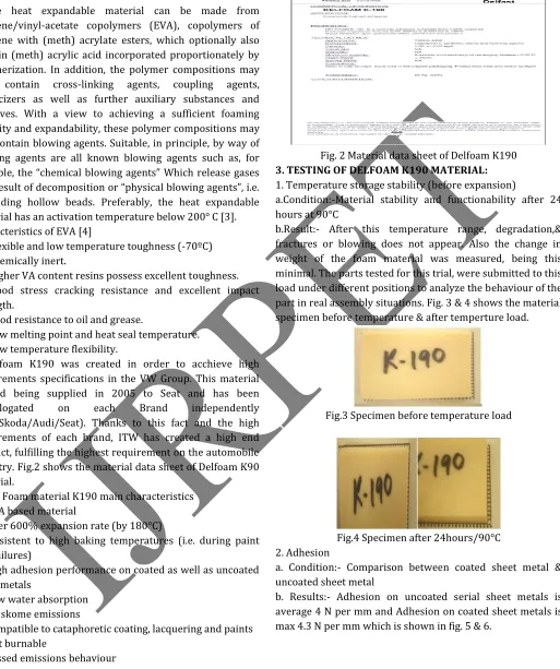
Delfoam K190 was created in order to acchieve high requirements specifications in the VW Group. This material started being supplied in 2005 to Seat and has been homologated on each Brand independently (VW/Skoda/Audi/Seat). Thanks to this fact and the high requirements of each brand, ITW has created a high end product, fulfilling the highest requirement on the automobile industry. Fig.2 shows the material data sheet of Delfoam K90 material.
ITW‘s Foam material K190 main characteristics 1) EVA based material
2) Over 600% expansion rate (by 180°C)
3) Resistent to high baking temperatures (i.e. during paint line failures)
4) High adhesion performance on coated as well as uncoated sheet metals
5) Low water absorption 6) No skome emissions
7) Compatible to cataphoretic coating, lacquering and paints 8) Not burnable
9) Passed emissions behaviour
Fig. 2 Material data sheet of Delfoam K190
3. TESTING OF DELFOAM K190 MATERIAL:
1. Temperature storage stability (before expansion)
a.Condition:-Material stability and functionability after 24 hours at 90°C
b.Result:- After this temperature range, degradation,& fractures or blowing does not appear. Also the change in weight of the foam material was measured, being this minimal. The parts tested for this trial, were submitted to this load under different positions to analyze the behaviour of the part in real assembly situations. Fig. 3 & 4 shows the material specimen before temperature & after temperture load.
Fig.3 Specimen before temperature load
Fig.4 Specimen after 24hours/90°C 2. Adhesion
a. Condition:- Comparison between coated sheet metal & uncoated sheet metal
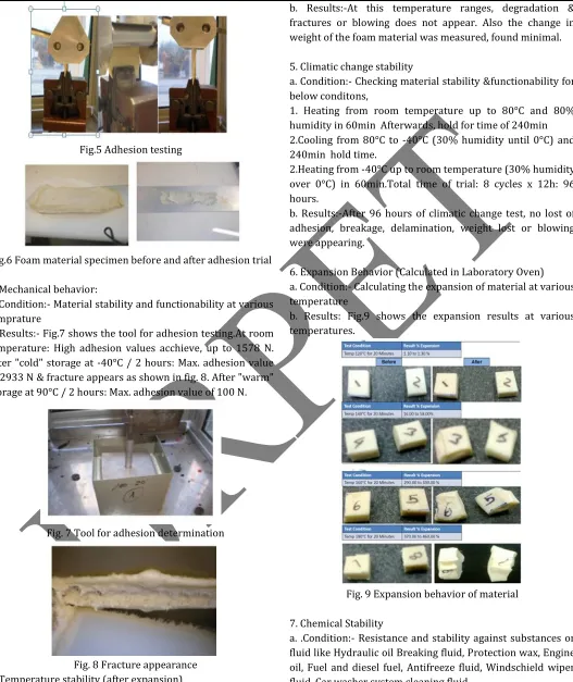
Fig.5 Adhesion testing
Fig.6 Foam material specimen before and after adhesion trial
3. Mechanical behavior:
a. Condition:- Material stability and functionability at various temprature
b. Results:- Fig.7 shows the tool for adhesion testing.At room temperature: High adhesion values acchieve, up to 1578 N. After "cold" storage at -40°C / 2 hours: Max. adhesion value of 2933 N & fracture appears as shown in fig. 8. After "warm" storage at 90°C / 2 hours: Max. adhesion value of 100 N.
Fig. 7 Tool for adhesion determination
Fig. 8 Fracture appearance 4. Temperature stability (after expansion)
a. Condition:- Material stability and functionability at below temprature/time. 180°C / 20min - 200°C / 60min - 220°C /
b. Results:-At this temperature ranges, degradation & fractures or blowing does not appear. Also the change in weight of the foam material was measured, found minimal.
5. Climatic change stability
a. Condition:- Checking material stability &functionability for below conditons,
1. Heating from room temperature up to 80°C and 80% humidity in 60min Afterwards, hold for time of 240min 2.Cooling from 80°C to -40°C (30% humidity until 0°C) and 240min hold time.
2.Heating from -40°C up to room temperature (30% humidity over 0°C) in 60min.Total time of trial: 8 cycles x 12h: 96 hours.
b. Results:-After 96 hours of climatic change test, no lost of adhesion, breakage, delamination, weight lost or blowing were appearing.
6. Expansion Behavior (Calculated in Laboratory Oven) a. Condition:- Calculating the expansion of material at various temperature
b. Results: Fig.9 shows the expansion results at various temperatures.
Fig. 9 Expansion behavior of material
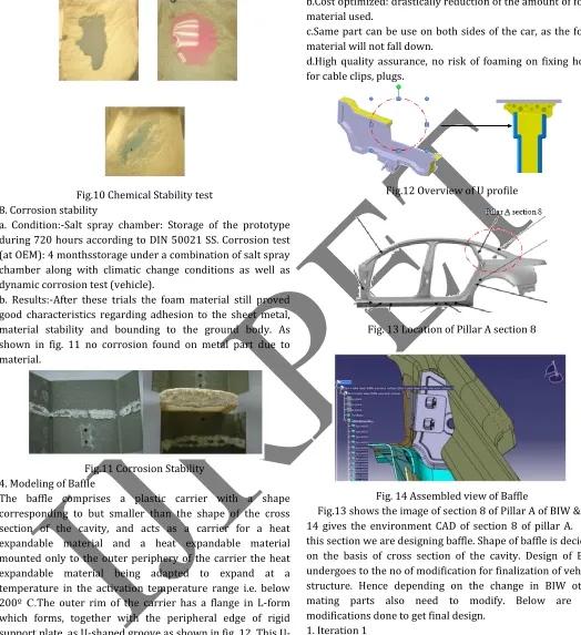
7. Chemical Stability
a. .Condition:- Resistance and stability against substances or fluid like Hydraulic oil Breaking fluid, Protection wax, Engine oil, Fuel and diesel fuel, Antifreeze fluid, Windschield wiper fluid, Car washer system cleaning fluid.
Fig.10 Chemical Stability test 8. Corrosion stability
a. Condition:-Salt spray chamber: Storage of the prototype during 720 hours according to DIN 50021 SS. Corrosion test (at OEM): 4 monthsstorage under a combination of salt spray chamber along with climatic change conditions as well as dynamic corrosion test (vehicle).
b. Results:-After these trials the foam material still proved good characteristics regarding adhesion to the sheet metal, material stability and bounding to the ground body. As shown in fig. 11 no corrosion found on metal part due to material.
Fig.11 Corrosion Stability 4. Modeling of Baffle
The baffle comprises a plastic carrier with a shape corresponding to but smaller than the shape of the cross section of the cavity, and acts as a carrier for a heat expandable material and a heat expandable material mounted only to the outer periphery of the carrier the heat expandable material being adapted to expand at a temperature in the activation temperature range i.e. below 200º C.The outer rim of the carrier has a flange in L-form which forms, together with the peripheral edge of rigid support plate, as shaped groove as shown in fig. 12. This U-shaped groove is adapted to receive the heat expandable material [3].
Advantage of U-shaped groove
a.Directed expansion of the foam material to the gap of the cavity. (Pay for what you use!) No expansion in non relevant areas.
b.Cost optimized: drastically reduction of the amount of foam material used.
c.Same part can be use on both sides of the car, as the foam material will not fall down.
d.High quality assurance, no risk of foaming on fixing holes for cable clips, plugs.
Fig.12 Overview of U profile
Fig. 13 Location of Pillar A section 8
Fig. 14 Assembled view of Baffle
Fig.13 shows the image of section 8 of Pillar A of BIW & fig. 14 gives the environment CAD of section 8 of pillar A. For this section we are designing baffle. Shape of baffle is decided on the basis of cross section of the cavity. Design of BIW undergoes to the no of modification for finalization of vehicle structure. Hence depending on the change in BIW other mating parts also need to modify. Below are the modifications done to get final design.
1. Iteration 1
Fig.15 shows the initial stage, at this slot size was 8.5mmX8.5mm and panel thickness was 0.8 mm. As per that design was made & weight 17.9gm.
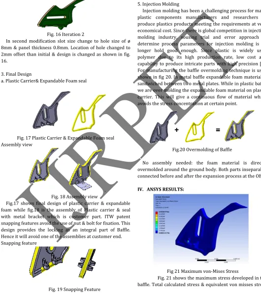
2. Iteration 2
Fig. 16 Iteration 2
In second modification slot size change to hole size of ø 8mm & panel thickness 0.8mm. Location of hole changed to 2mm offset than initial & design is changed as shown in fig. 16.
3. Final Design
a. Plastic Carrier& Expandable Foam seal
Fig. 17 Plastic Carrier & Expandable Foam seal Assembly view
. Fig. 18 Assembly view
Fig.17 shows final design of plastic carrier & expandable foam while fig.18 is the assembly of Plastic carrier & seal with metal bracket which is customer part. ITW patent snapping features avoid the use of nut & bolt for fixation. This design provides the locking as an integral part of Baffle. Hence it will avoid one of the assemblies at customer end. Snapping feature
Second important thing about the design is both side fixation and locking feature permit the use of same baffle for LH & RH side of pillar as shown in fig.19 called as snapping features. This will save the cost of development of new baffle for either LH or RH section.
5. Injection Molding
Injection molding has been a challenging process for many plastic components manufacturers and researchers to produce plastics products meeting the requirements at very economical cost. Since there is global competition in injection molding industry, sousing trial and error approach to determine process parameters for injection molding is no longer hold good enough. Since plastic is widely used polymer due to its high production rate, low cost and capability to produce intricate parts with high precision [5]. For manufacturing the baffle overmolding technique is used shown in fig 20. In metal baffle expandable foam material is sandwiched between two metal plates. While in plastic baffle we are over molding the expandable foam material on plastic carrier. This will give a continuous flow of material which avoids the stress concentration at certain point.
Fig.20 Overmolding of Baffle
No assembly needed: the foam material is directly overmolded around the ground body. Both parts inseparably connected before and after the expansion process at the OEM.
IV. ANSYS RESULTS:
Fig 21 Maximum von-Mises Stress
developed in part is same i.e. 6.92 N/mm2. Hence design is safe.
V. PROTOTYPING & TESTING:
Prototyping is done to validate the transmission loss between the metal baffle & plastic baffle. In proto plastic baffle expandable foam material is sandwiched between two plastic carries with the help of screw fittings. Fig. 22 shows the images of prototype plastic baffle.
Fig.22 Prototype of Plastic Baffle
To check the transmission loss baffle is fitted in the pillar section. First metal baffle fitted in the pillar section & heated at 180˚C temperature for 20 min. at this temperature foam gets expand & provide the sealing to the pillar section as shown in fig.23. This pillar section is tested in laboratory to check the sound transmission or transmission loss from one end to other end of pillar. Same procedure will be carried out for plastic baffle & transmission graph is plotted between sound levels in db & frequency.
Fig. 23 Images of metal & plastic baffles after heat cycle fixed at the same place in same section
Fig. 24 Laboratory testing procedure of Baffle
Fig. 24 shows the laboratory testing method of baffle for sound level measurement from one channel to other. For this Bruel & kjaer type 2270 sound level measurement instrument is used. This instrument can
measure 4.2 Hz to 22.4 kHz broadband linear frequency range.
Fig. 25 Graph of transmission loss comparison for Metal & Plastic Baffle
VI. COMPARISON BETWEEN METAL & PLASTIC BAFFLE:
Table. 1 Comparison between metal & plastic baffle
Table 1 shows the comparison between the metal & plastic baffle in terms of design, no of parts, assembly & overall cost of baffle.
VII. CONCLUSION:
From fig.25 we can conclude that, transmission loss of plastic baffle with reference to the metal baffle is same & can achieve upto 70db transmission loss. Also form table 1 shows the advantages of plastic baffle over metal. By using plastic baffle 45.7% cost improvement can be achieved.
VIII. ADVANTAGES:
2) Less foam with high performance compared to completion part
3) Less weight, Less Assembly i.e. less installed cost
4) Reduces welding, Assembly at Tier1 eliminating logistic issue Ease of Assembly at OEM with ITW click – On solution
5) No red rust issues (inside vehicle) which is due to welding 6) This design ensures Foam Reaches corner sealing with
guided expansion
7) Automated process with Robo assisted 2K molding gives more consistency
REFERENCES:
1) Philip E. Weber, Novi, MI (US), ACOUSTIC BAFFLE, US 20050082111A1, Apr. 21, 2005.
2) Jean-lPlerre Monnet, Boulleret (FR), Fabmel’runarety,$I-$at11r(FR); SébastienPeget, Saint BouiZe (FR); Gregory Magnet’ St'LOup (FR), ACOUSTIC BAFFLE, US008215704B2, Jul. 10, 2012
3) Jean-Pierre Monnet, Boulleret (FR); FabricePrunarety, St. Satur (FR); SebastienPeget, Saint BouiZe (FR); Gregory Magnet, St.Loup (FR), ACOUSTIC BAFFLE, US 20110057392A1, Mar. 10, 2011.
4) Dr.J.S.Anand, Applications of Plastic, Central institute of Engineering andTechnology, 1997, pg 99 & 111.