VOLUME 3, ISSUE 4, Apr.-2017
174 | P a g e
STRESS CALCULATION FOR RECTANGULAR PLATE USING SIMPLIFIED
ANALYTICAL METHOD
ANJAN KUMAR NANDI
Dept. of Mechanical Engineering JCOE, Kuran Pune, India, [email protected]
HREDEY MISHRA
Dept. of Mechanical Engineering JCOE, Kuran Pune, India, [email protected]
ABSTRACT:
Plate stress calculation is a fundamental problem of strength of material. Accurate analytical solution needs rigorous analytical calculation of solving differential equations. Such calculation gives values bending moment and stresses at all points. In the simple analytic calculation mentioned here we have calculated bending moment across most critically loaded section. We have first selected the most critical section of the plate where the max bending moment and max stresses are expected to occur. Then we have calculated bending moment (average) across that section using simple methods of equilibrium of forces and moments. Thereafter we have calculated stresses corresponding to that bending moment using strength of material formula. FEM analysis using ANSYS is carried out to find out exact max stresses (Von Misses). Four different combinations of support condition and load cases are done. We have checked the error in such approximate calculate analytic calculation.
KEYWORDS: rectangular, plate, analytical, simplified method, ANSYS, static structural.
I. INTRODUCTION:
In strength of materials, calculating stresses of a loaded plate is a fundamental problem. Detailed analysis has been done by Timoshenko & Woinosky-Krieger [1] and various other scientists. Such detailed analysis needs solving complex differential equations. Such analysis gives moment & stress equations from where we can obtain moments and stresses at every points on the plate. However many a times we are not interested about stresses on every points but only on max stress which will be the basis of our design (say calculating plate thickness). However many a times during design process we assume the values of such parameters (say thickness) then we calculate stress by using FEM analysis assuming the plate thickness. FEM analysis is done to find out max stress based on the assumed plate thickness. If stress is more than allowable stress or stress is very low we change the plate thickness to obtain optimum value. In such case it is essential that our initial guess be fairly accurate so that we can obtain optimum value with minimum iteration. Here we have calculated initial value by simple method of force
and moment balance to calculate bending moment which is very close to the actual max bending moment and stress. These values can be used to calculate stresses or required plate thickness. Plate thickness obtained by this method can be used for final FEM analysis.
II. ANALYTICALMETHOD:
Following are the basics considered for analytical calculation:
Plate dimensions: Length b (longer side)
Width a
Thickness h
Uniform pressure p
Total load on plate w = p*(a*b)
Reaction forces R
Moment per unit length M
A. LOAD CASES:
1) Case-I: Rectangular Plate With Corner Support and
uniformly distributed load
Here, a rectangular plate is simply supported at four corners and a uniformly distributed load is applied is applied over top surface of the plate.
Total load on plate is
w=p*a*b (1)
Where w is total load on the plate.
For symmetry all four reactions forces on the corner supports will be same (R)
w=4R or R=w/4=pab/4 (2)
Bending moment & stress on the plate will vary and maximum is expected to occur on the centre of the plate. One critical line which is parallel to shorter side of plate passing through centre is considered for calculating the bending moment. We will now calculate average bending moment along this line. This will be very near to max value.
VOLUME 3, ISSUE 4, Apr.-2017
2) Case-II: Rectangular Plate With Corner Support And
Concentrated Load At Centre
Here, a rectangular plate is simply supported at four corners and a concentrated load is applied at centre of the plate.
For symmetry all four reactions will be same (R) w=4R or R=w/4=pab/4 (5)
Here also, bending moment & stress on the plate will vary and maximum is expected to occur on the centre of the plate. One critical line which is parallel to shorter side of plate passing through centre is considered for calculating the bending moment. We will now calculate average bending moment along this line. This will be very near to max value.
Equilibrium of moments about XX axis:
(R*b/2)*2=M*a (6)
M= wb/4a (7)
Where, M is average bending moment per unit length along XX.
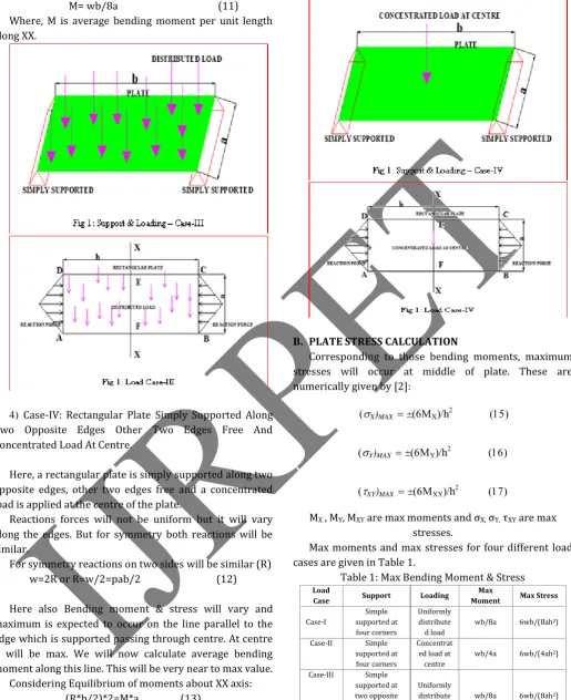
3) Case-III: Rectangular Plate Simply Supported along
two opposite edges other two edges Free and Uniformly Distributed Load
Here, a rectangular plate is simply supported along two opposite edges, other two edges free and a uniform distributed load is applied on top surface of the plate.
Reactions forces will not be uniform but it will vary along the edges. But for symmetry both reactions will be similar (both varying similarly)..
Let us consider total reaction at each side is R and the resultant is expected to occur through centre of area of the force diagram. Due to symmetry it will through centre of each side.
Total load on plate is
w=p*a*b (8) w=2R or R=w/2=pab/2 (9)
Bending moment & stress will vary and maximum is expected to occur on the line parallel to the edge which is supported passing through centre. At centre it will be max. We will now calculate average bending moment along this line. This will be very near to max value.
Considering Equilibrium of moments about XX axis:
VOLUME 3, ISSUE 4, Apr.-2017
176 | P a g e M= wb/8a (11)
Where, M is average bending moment per unit length along XX.
4) Case-IV: Rectangular Plate Simply Supported Along
Two Opposite Edges Other Two Edges Free And Concentrated Load At Centre.
Here, a rectangular plate is simply supported along two opposite edges, other two edges free and a concentrated load is applied at the centre of the plate.
Reactions forces will not be uniform but it will vary along the edges. But for symmetry both reactions will be similar.
For symmetry reactions on two sides will be similar (R) w=2R or R=w/2=pab/2 (12)
Here also Bending moment & stress will vary and maximum is expected to occur on the line parallel to the edge which is supported passing through centre. At centre it will be max. We will now calculate average bending moment along this line. This will be very near to max value.
Considering Equilibrium of moments about XX axis: (R*b/2)*2=M*a (13)
M= wb/4a (14)
Where, M is average bending moment per unit length along XX.
B. PLATE STRESS CALCULATION
Corresponding to those bending moments, maximum stresses will occur at middle of plate. These are numerically given by [2]:
X)MAX±Xh
Y)MAX±Yh
XY)MAX±XYh
MX , MY, MXY are max moments and σX, σY, τXY are max stresses.
Max moments and max stresses for four different load cases are given in Table 1.
Table 1: Max Bending Moment & Stress Load
Case Support Loading
Max
Moment Max Stress
Case-I
Simple supported at four corners
Uniformly distribute
d load
wb/8a 6wb/(8ah2)
Case-II Simple
supported at four corners
Concentrat ed load at centre
wb/4a 6wb/(4ah2)
Case-III Simple
supported at two opposite edges other two
free
Uniformly distribute
d load
wb/8a 6wb/(8ah2)
Case-IV Simple
supported at two opposite edges other two
free
Concentrat ed load at centre
VOLUME 3, ISSUE 4, Apr.-2017 III. ANSYSANALYSIS:
Plate dimensions: Length- b = 1000 mm Width- a = 500 mm Thickness- h = 20 mm Uniform pressure p = 5000 / (1000*500) =0 .01 MPa
Total load on plate w = p* (a*b) = 5000 N Support Condition:
Case I & II – Simply supported at four vertices
Case III & IV – Simply supported at two opposite faces (shorter faces , along width i.e. a), other two edges are free.
External Load:
Case I & III– Uniformly distributed load on top surface of the plate.
Case II & IV– Concentrated load on centre of top surface of the plate.
Max Von Misses stress and Max Principal Stress are calculated for all four cases as mentioned in analytical calculation. Results are tabulated below:
ANSYS Workbench Version: 14.5
Analysis type: Static structural analysis. (Self weight of plate is not considered for analysis)
Material – Structural Steel
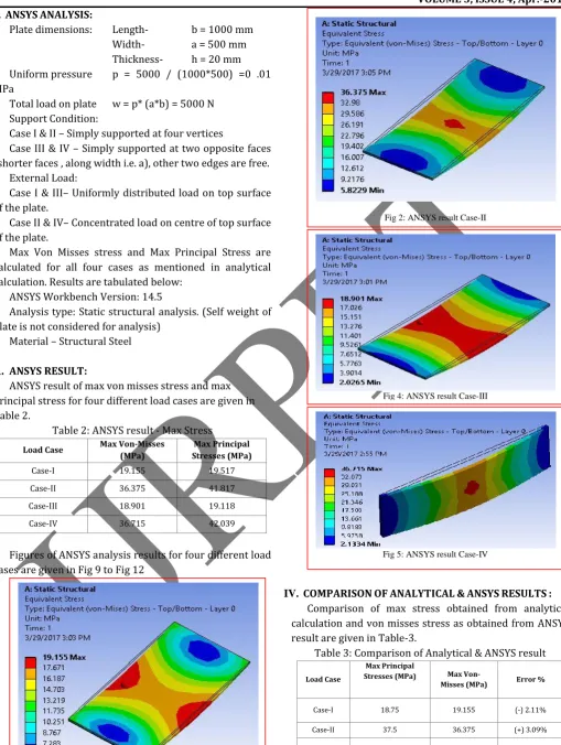
A. ANSYS RESULT:
ANSYS result of max von misses stress and max principal stress for four different load cases are given in Table 2.
Table 2: ANSYS result - Max Stress Load Case Max Von-Misses
(MPa)
Max Principal Stresses (MPa)
Case-I 19.155 19.517
Case-II 36.375 41.817
Case-III 18.901 19.118
Case-IV 36.715 42.039
Figures of ANSYS analysis results for four different load cases are given in Fig 9 to Fig 12
IV. COMPARISONOFANALYTICAL&ANSYSRESULTS: Comparison of max stress obtained from analytical calculation and von misses stress as obtained from ANSYS result are given in Table-3.
Table 3: Comparison of Analytical & ANSYS result
Load Case
Max Principal
Stresses (MPa) Max
Von-Misses (MPa) Error %
Case-I 18.75 19.155 (-) 2.11%
Case-II 37.5 36.375 (+) 3.09%
Case-III 18.75 18.901 (-) 0.8 %
Case-IV 37.5 36.715 (+) 2.14%
Fig 1:ANSYS result Case-I
Fig 2: ANSYS result Case-II
Fig 3: ANSYS result Case-II
Fig. 1. Example of a figure caption. (figure caption)
Fig 4: ANSYS result Case-III
VOLUME 3, ISSUE 4, Apr.-2017
178 | P a g e It is observed from the table that the variation in stress between analytical methods is less than 4%.
V. CONCLUSION:
Analytical calculation mentioned here is very simple and quick. In this calculation we are actually calculating average stress across the section which we have considered not the maximum stress at a particular point, hence this is an approximate method. It is necessary that such section be carefully selected. From the above analysis it is clear that error is not very high. Hence, we can use the above procedure for getting approximate value of stress. In many case during design we assume values of the parameters may be plate thickness in case of plate analysis
then we calculate actual values and compare these with allowable stresses. Above mentioned procedure can be used to obtain these values which can then be used in further detail analysis or by using fem software like ANSYS to obtain accurate values.
REFERENCES:
1) Stephen P. Timoshenko, S. Woinosky-Krieger,”Theory
of plates and shells”, Second Edition,McGraw Hill,1959
2) Richard G. Budynas, “Advanced Strength and applied
stress analysis”, Second Edition.Mc Graw Hill, 1999