e-ISSN: 2278-067X, p-ISSN: 2278-800X, www.ijerd.com
Volume 6, Issue 11 (April 2013), PP. 62-67
Short Circuit Analysis on 400 Kv Sub-Station Soja
1
V.J.Rathod,
2prof. G R.Patel
1M.E. [Power System] Student, Department of Electrical Engineering,
S.K.Patel College of Engineering Visnagar, Gujarat.
2
Asst.Professor, Department of Electrical Engineering, S.K.Patel College of Engineering Visnagar, Gujarat.
Abstract:- A Short Circuit analysis is used to determine the magnitude of short circuit current. To
demonstrate its use, a simple 19-bus system was selected as a example of 400kV SOJA substation.
Keywords:- Fault current, short circuit
I.
INTRODUCTION
The reliability of power supply implies much more than merely being available. Short circuit studies and hence the fault analysis are very important for the power system studies since they provide data such as voltages and currents during and after the various types of faults which are necessary in designing the protective schemes of the power system. Current that flows in the power system components just after the occurrence of faults, that flows a few cycles later and the steady state value (i.e. sustained value of) fault currents differ very much from each other. Protective scheme, basically consists of protective relays and switch gears such as circuit breakers etc.
There are different types of faults in the power system which can broadly be divided into symmetrical and unsymmetrical faults [4].The currents and voltages resulting from various types of faults occurring at different
locations throughout the power system network must be calculated in order to provide sufficient data for designing the protective scheme [1].
II.
OBJECTIVE
Aselectrical utilities grow in size the number of interconnections increased, planning for future expansion going to be complex. In the paper circuit analysis has been carried out using Mi-power software on 400 kV soja substation.
III.
SHORT CIRCUIT STUDY
Short circuit studies are very important from the operating and planning points of view. Abnormal conditions can arise in a power system owing to short circuits between two phases, or a line snapping and making contact with ground or a lightning stroke hitting a particular transmission line. These give rise to heavy current in the system. Before these current can do any damage to equipments such as expensive generator and transformer, the faulty parts of the transmission system must be isolated [5]. This is done by circuit breakers
actuated through sensing relays hence, the determination of the interrupting duties of circuit breaker as well as relay setting is needed. This information can be easily calculated if we know the current in the system on the occurrence of a fault such investigation are termed as short circuit studies. Consequently, the short circuit studies become essentially a linear network problem since the generator will be represented by means of a voltage source in series with a reactance (generally the transient or sub transient reactance).
There are different types of faults in the power system which can broadly be divided into symmetrical and unsymmetrical faults [2].
Certain Assumptions Will Be Made:
[1] The generated e.m.f. system is of positive sequence only.
[2] The impedance of the fault is zero.
[3] Any one phase shall be taken as the reference phase.
IV.
VARIOUS TYPE OF FAULTS
1. Line to ground fault (L-G) 2. Line to line fault (L-L)
4. Three phase to ground fault(L-L-L-G)
V.
AN INTRODUCTION ABOUT 400KV S/S SOJA
The Gujarat Energy Transmission Corporation has established a 400kV SOJA sub-station it is 1.5km between from Gojariya- Gandhinagar highway.
The incoming line of 400kV at Soja s/s is from Wanakbori and PGCIL 400kV s/s which is single circuit type transmission line. The tower required for eraction of 400kV transmission line which is coming from Wanakbori and PGCIL s/s are of three type i.e., A, type C and type D tower. The total number of tower required between Wanakbori & PGCIL and soja s/s is 412. The line has charged since 28th January 1987.In single line diagram two incoming lines from Wanakbori and PGCIL of 400kV, and two incoming line from Gandhinagar of 220kV.
Figure-1 Single Line Diagram of 400 kV Soja Substation
5.1 Objective
Short circuit analysis taken here for case study is with reference to the 400 kV sub-station of Soja, Gandhinagar. The network shown in Figure-1 is a single line diagram is prepared using Mi-Power software. The data required for the network, some of which are taken from 400 kV Soja sub-station. Entered in the Mi-Power database.
In the network taken here, there are 19buses, 3transformers, 12transmission lines and 3 generators.
5.2 RESULTS & DISCUSSIONS:
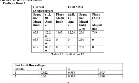
Faults on Bus-17
Current (Amps/degree)
Fault MVA
Seque nce Magn itude
(1,2, 0) Angl e
Phase Magn itude
(A,B, C) Angl e
Seque nce Magni tude(1 ,2,0)
Phase (A,B,C ) Magnit ude
655 82.2 6
1965 82.26 250 749
655 82.2 6
0 0 250 0
655 82.2 6
0 0 250 0
Table 5.1: Fault at bus 17
Post Fault Bus voltages
Bus no. 1 2 0
1 0.922 0.989 0.905
3 0.825 0.943 0.816
4 0.882 0.978 0.868
5 0.856 0.966 0.896
6 0.837 0.957 0.829
7 0.823 0.967 0.821
8 0.821 0.825 0.967
9 0.878 0.984 0.875
10 0.820 0.972 0.823
11 0.809 0.967 0.812
12 0.808 0.966 0.811
13 0.808 0.966 0.811
14 0.811 0.807 0.964
15 0.810 0.808 0.966
16 0.811 0.808 0.966
17 0.811 0.669 0.965
18 0.807 0.965 0.810
19 0.807 0.965 0.810
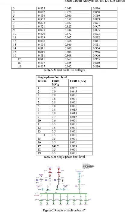
Table 5.2: Post Fault Bus voltages
Single phase fault level
Bus no. Fault
MVA
Fault I (KA)
1 0.9 0.047
2 0.9 0.045
3 0.8 0.001
4 0.8 0.001
5 0.8 0.001
6 0.8 0.001
7 0.8 0.013
8 0.8 0.013
9 0.7 0.012
10 0.6 0.001
11 0.5 0.001
12 0.5 0.001
13 0.5 0.001
14 0.5 0.001
15 0.5 0.001
16 0.5 0.001
17 748.7 1.965
18 0.5 0.001
19 0.5 0.001
Table 5.3: Single phase fault level
Faults on Bus-15
Current (Amps/degree) Fault MVA
Sequ ence Mag nitud e (1,2, 0) Ang le Pha se Mag nitu de (A, B,C ) An gle Sequenc e Magnitu de(1,2,0) Phas e (A,B, C) Mag nitud e
3581 84.4 0
358 1
84. 40
1364 1364
0 90.0 0
358 1
155 .60
0 1364
0 90.0 0
358 1
35. 60
0 1364
Peak asymmetrical Short-Circuit Current :7313
Amps
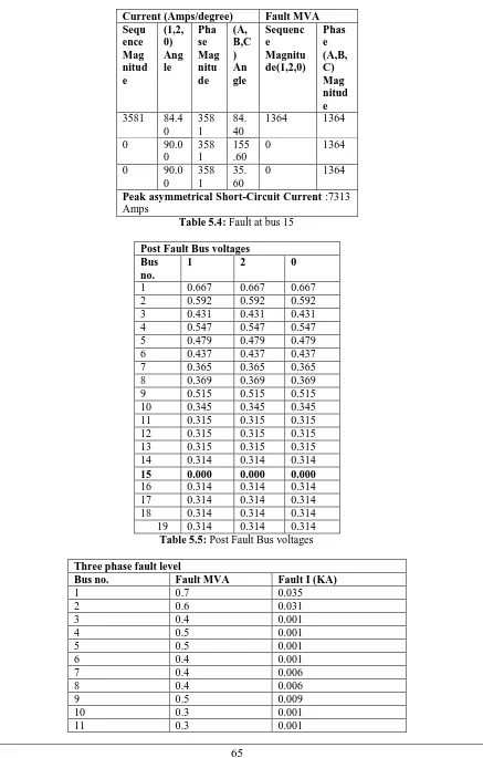
Table 5.4: Fault at bus 15
Post Fault Bus voltages Bus
no.
1 2 0
1 0.667 0.667 0.667 2 0.592 0.592 0.592 3 0.431 0.431 0.431 4 0.547 0.547 0.547 5 0.479 0.479 0.479 6 0.437 0.437 0.437 7 0.365 0.365 0.365 8 0.369 0.369 0.369 9 0.515 0.515 0.515 10 0.345 0.345 0.345 11 0.315 0.315 0.315 12 0.315 0.315 0.315 13 0.315 0.315 0.315 14 0.314 0.314 0.314
15 0.000 0.000 0.000
16 0.314 0.314 0.314 17 0.314 0.314 0.314 18 0.314 0.314 0.314 19 0.314 0.314 0.314
Table 5.5: Post Fault Bus voltages
Three phase fault level
Bus no. Fault MVA Fault I (KA)
1 0.7 0.035
2 0.6 0.031
3 0.4 0.001
4 0.5 0.001
5 0.5 0.001
6 0.4 0.001
7 0.4 0.006
8 0.4 0.006
9 0.5 0.009
10 0.3 0.001
12 0.3 0.001
13 0.3 0.001
14 0.3 0.001
15 1364.4 3.5881
16 0.3 0.001
17 0.3 0.001
18 0.3 0.001
19 0.3 0.001
Table 5.6: Three phase fault level
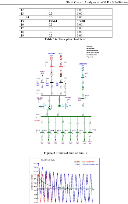
Figure-3 Results of fault on bus-17
VI.
CONCLUSION
Above result shows the fault MVA and fault current on the faulted bus-17, 704.8 MVA and 1.850 KA respectively.
Above result shows the 3 phase fault MVA and fault current on the faulted bus-15, are 1300 MVA and 3.413 KA respectively.
Mi-power generated single line diagram shows the fault MVA and phase angle on each bus and on each line.
REFERENCES
[1]. Nedic, Dusko, Bathurst, Graeme & Heath, John (2007) “A Comparison of Short Circuit Calculation Methods and Guidelines for Distribution Networks” CIRED2007 session3, paper No. 0562. 19th International Conference on Electricity Distribution; 21-24 May 2007; Vienna.
[2]. Z.X. Han, “Generalized Method of Analysis of Simultaneous Faults in Electric Power Systems,” IEEE
Transactions on Power Apparatus andSystems, Vol. 101, No 10, pp. 3933–3942, Oct. 1982.
[3]. V. Brandwajn and W.F. Tinney, “Generalized Method of Fault Analysis,” IEEE Transactions on
Power Apparatus and Systems, Vol. 104, No 6, pp. 1301–1306, June 1985.
[4]. Stagg GW, El-Abiad AH. Computer methods in power system analysis. McGraw-Hill; 1968. [5]. Kothari D.P., Nagrath I.J. Modern power system analysis. McGraw-Hill; 2004.
[6]. Grainger J.J., Grainger J.J., Stevenson WD. “Power system analysis” McGraw-Hill; 1994. [7]. Sadat H. “Power system analysis” McGraw-Hill; 2004