Page 290 www.ijiras.com | Email: contact@ijiras.com
Fourier Transform And Its Application In Modulation Techniques
Mrs. Supriya Nilesh Thakur
Mrs. Megha Kishor Kothawade
Assistant Professor, Basic Engineering Science Department, Guru Gobind Singh College Of Engineering And Research Centre,
Nashik
I. BACKGROUND
Mathematics is everywhere in every phenomenon, technology, observation, experiment etc. All we need to do is to understand the logic hidden behind. Since mathematical calculations give way to the ultimate results of every experiment, it becomes quite pertinent to analyse those calculations before making conclusions. The present era of communication technology has provided some major catalysts in developing the modern human society. Communication includes automatic transmission of data over wires and radio circuits through signals. In communication systems, signal processing, and electrical Engineering, signal is a function that conveys information about the behaviour or attributes of some phenomenon. Signal is basically a means of transmitting information in accordance with certain prearranged system or code. It includes, among others, audio, video, speech, image, communication, geophysical, sonar, radar, medical and musical signals.
II. ROLE OF FOURIER TRANSFORM (FT) IN MODULATION TECHNIQUES
Jean Baptiste Joseph Fourier, the French mathematician/physicist made an astonishing discovery in 1800. According to Fourier, every function could be represented by an infinite series of elementary trigonometric functions: sine and cosine. For example, consider decomposing the signal into its trigonometric constituents reveals the fundamental frequencies (tones, overtones, etc.) that combine to produce the instrument’s distinctive timbre. Fourier analysis is an essential component of much of modern applied (and pure) mathematics. It forms an exceptionally powerful analytical tool for solving a broad range of partial differential equations. Fourier analysis lies at the heart of signal processing, including audio, speech, images, videos, seismic data, radio transmissions, and so on. Many modern technological advances, including television, music CD’s and DVD’s, cell phones, movies, computer graphics, image processing, and fingerprint analysis and storage, are, in one Abstract: The Fourier Transform is a tool that breaks a waveform (a function or signal) into an alternate representation characterised by sine and cosines.The Fourier Transform shows that any waveform can be re-written as the sum of sinusoidal function.
Communication is all based on Mathematics, be it digital, wired or wireless. Signal transmission is done through modulation i.e. amplitude modulation (AM), frequency modulation (FM) or phase modulation (PM). At the receiving end the transmitted signal is demodulated to extract the information. All these techniques are based on pure mathematics. While modulating the information signal, a high frequency sinusoidal carrier signal is used to transmit the message signal through a medium (cable or air). It is then received and demodulated using Fourier Transform analysis. So for understanding the communication technology, the processes of modulation, demodulation and Fourier Transform need to be explored first.
Page 291 www.ijiras.com | Email: contact@ijiras.com way or another, founded upon the many ramifications of
Fourier theory.
The principle of the Fourier transform is that any signal, such as the sound produced by a musical instrument, e.g., piano, violin, trumpet, or drum, any sound recording can be statistical applications across a broad range of applications.
Frequency domain analysis and Fourier transforms are a cornerstone of signal and system analysis. These ideas are also one of the conceptual pillars within electrical engineering. Among all of the mathematical tools utilized in electrical engineering, frequency domain analysis is arguably the most far-reaching. In fact, these ideas are so important that they are widely used in many fields – not just in electrical engineering, but in practically all branches of engineering and of Fourier Transform because sound may be represented by a complex combination of their waves. Humans, very easily perform FT mechanically almost every day without having idea of it. For example, when you are in a room with a great deal of noise and you selectively hear your name above the noise, you have just performed FT. FT is the mathematical way of gathering unique frequencies from a broad spectrum of frequencies, like in the FID spectrum obtained in NMR. Fourier Transform can be used to convert from the series of numbers to sound.
III. MATHEMATICS BASE FOR MODULATION TECHNIQUE
MODULATION
Modulation is a process of translating information signal from low band frequency to high band frequency that suits the transmission medium. The inputs to the modulator are carrier and information (modulating) signals while the output is called the modulated signal. Modulating or information signal is usually of low frequency, so it cannot travel far. It needs a carrier signal of higher frequency for long distance destination.
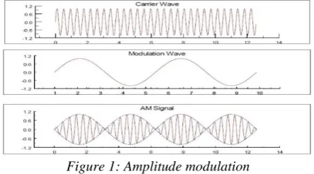
Modulation With the proper equipment, radio signals can be transmitted and received over large distances. Information may therefore be exchanged over large distances by encoding information on radio waves. This is accomplished through modulation of radio signals. Modulation is the process of encoding information onto a carrier signal which has frequency Fc. This carrier signal is called the modulated signal, while the information carrying, or baseband signal is referred to as the modulating signal. Two types of modulation will be reviewed in this module. Amplitude modulation consists encoding information onto a carrier signal by varying the amplitude of the carrier. Frequency modulation consists of encoding information onto a carrier signal by varying the frequency of the carrier. Once a signal has been modulated, information is retrieved through a demodulation process. AMPLITUDE MODULATION
Amplitude modulation consists encoding information onto
a carrier signal by varying the amplitude of the carrier.
Figure 1: Amplitude modulation
SUPPRESSED CARRIER AMPLITUDE MODULATION (DOUBLE SIDEBAND)
A general sinusoidal signal can be expressed as f ( t) =_
A( t ) cos where the amplitude A and phase angle _ may, in general, be functions of time. It is convenient to write time
varying angle as .
Therefore the sinusoidal signal may be expressed as
Figure 2: Amplitude modulation (suppressed carrier)
The term A(t) is called the envelope of the signal f(t), and as is called the carrier frequency. The process of amplitude modulation consists of the amplitude of the carrier wave being varied in sympathy with a modulating signal. A mathematical representation of an amplitude modulated signal is obtained by setting =0 in the expression for the general sinusoidal signal, and letting the envelope A(t) be proportional to a modulating signal f(t). What results is a new (modulated)
signal, given by .
The spectrum of the modulated signal y( t) can be found by using the modulation property of the Fourier transforms. The Fourier transform pair was defined as,
The Fourier transform of a signal is then F
Thus the Fourier transform of may be expressed
F
Page 292 www.ijiras.com | Email: contact@ijiras.com When y(t) is expressed in this form, and from the example
above, it can be seen that the Fourier transform of y(t) is given by
F
Thus, the spectrum of is translated by It is seen that the modulation process causes frequencies associated with the modulating signal to disappear. Instead, a new frequency spectrum appears, consisting of two sidebands, known as the upper sideband (USB), and the lower sideband (LSB). The spectrum of the modulated signal y(t ) does not contain the spectrum of the original carrier, but is still centered about the carrier frequency . Thus this type of modulation is referred
to as double-sideband, suppressed-carrier amplitude
modulation. A block diagram of the suppressed carrier amplitude modulation operation is presented in Figure 2.
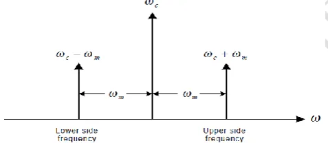
If the modulating signal contains a single frequency ,
then and
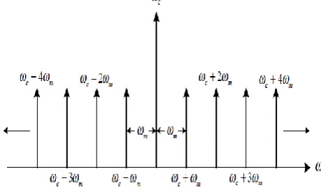
, (Figure 3). If modulating signal has a bandwidth of , then
F( $ the spectrum of will extend from to .The upper sideband of the spectrum of the modulated signal Y( will extend from to Likewise, the lower sideband will extend from to . Both the negative and positive frequency components of the modulating signal appear as positive frequencies in the spectrum of the modulated signal y(t). It is also seen that the bandwidth of is doubled in the spectrum of the modulated signal when this type of modulation is employed.
Figure 3: Single modulating frequency AM signal spectrum
AM DEMODULATION
An AM signal is demodulated by first mixing the modulated signal y(t ) with another sinusoid of the same carrier frequency,
( =
The Fourier transform of this signal is
F ( F
F( =
By using a low-pass filter, the frequency components centered at can be removed to leave only the term. It is obvious that in order to properly recover the original signal it is necessary that
THE ENVELOPE DETECTOR
An envelope detector is any circuit whose output follows the envelope of an input signal. The simplest form of such a detector is a non-linear charging circuit which has a fast charge time and a slow discharge time. This is easily implemented by placing a diode in series with a parallel combination of a capacitor and a resistor. The envelope of an input signal is detected by the following process:
The input waveform (in this case a large carrier AM signal) charges the capacitor to the maximum value of the waveform during positive half-cycles of the input signal.
As the input signal falls below maximum, the diode becomes reverse biased, and switches off.
The capacitor then begins a relatively slow discharge through the resistor until the next positive half-cycle. When the input signal becomes greater than the capacitor voltage, the diode becomes forward biased, and the capacitor charges to a new peak value. For optimum operation, the discharge time constant RC is adjusted so that the maximum negative rate of the envelope never exceeds the exponential discharge rate.
If the time constant is too large, the envelope detector may miss some positive half-cycles of the carrier, and will not correctly reproduce the envelope of the input signal.
If the time constant is too small, the detector generates a ragged signal.
FREQUENCY MODULATION
Frequency modulation consists of encoding information
onto a carrier signal by varying the frequency of the carrier. Once a signal has been modulated, information is retrieved through a demodulation process.
Figure 4: Frequency modulation
Frequency modulation is a type of angle modulation. Angle modulation changes the phase of a signal as well as its amplitude, where amplitude modulation leaves the phase unchanged. Phase modulation is another type of angle modulation very similar to frequency modulation.
The general form of a sinusoidal signal can be written as The instantaneous angular frequency of this signal is the derivative of the phase
Page 293 www.ijiras.com | Email: contact@ijiras.com This definition of instantaneous frequency suggests two
obvious methods of angle modulation:
- If the phase angle of a carrier with fundamental frequency is varied linearly with a modulating waveform f(t)
t+
The modulated signal is said to be phase modulated. Here , , are constants.
The instantaneous frequency of a phase modulated signal is given by
+
If the instantaneous frequency of a carrier with fundamental frequency $ is varied in proportion to an input modulating signal f(t), such that
+
the resulting modulated signal is said to be frequency
modulated. Here and are constants. The phase angle
associated with the FM signal is given by
which may also be expressed
It can be seen in Figure 4.that phase and frequency modulation are closely related. For both phase and frequency modulation, the modulating signal causes the carrier to increase and decrease from the fundamental frequency while the amplitude remains constant. For the FM signal, the frequency rises with positive modulating amplitudes and falls with negative modulating amplitudes. For the PM signal, the frequency rises with increasing modulating amplitudes, and decreases with decreasing modulating amplitudes.
FREQUENCY MODULATION HAS SEVERAL
ADVANTAGES OVER AMPLITUDE MODULATION
The radiated signal level remains constant, therefore transmitters can be run at a constant Power output.
Amplitude variations due to external interference sources are not interpreted as signals.
Selective fading does not occur because the amplitude of the carrier is constant.
It is possible to design systems having better dynamic range and signal-to-noise ratio.
The obvious disadvantage of frequency modulation is that a greater bandwidth is required than for amplitude modulation.
Another significant difference between amplitude and angle modulation has to do with the Relationship between the modulated and modulating signals. When signals are Amplitude
Modulated, one-to-one correspondence exists between the modulated and modulating signals. In this case the modulation is said to be linear. This linear relationship does not always exist for phase and frequency Modulation. As a result, the sidebands associated with angle modulation do not obey the principle of superposition.
FM DEMODULATION
Many methods of recovering information from an FM waveform exist. One method involves the use of a system that has a linear frequency-to-voltage transfer characteristic. This type of system is referred to as a discriminator. The simplest such device is an ideal differentiator.
A general FM waveform may be expressed:
If A is a constant then
If , then the expression above has the from of an AM signal with envelope
having frequency
Thus, the differentiator has converted the FM signal into an AM signal with a slight frequency variation (assuming that ) The original waveform may now be recovered by an envelope detector.
Figure 4: Frequency modulation signal spectrum band
IV. CONCLUSION
The Fourier Transform can be used to analyse and demonstrate different modulation signals. Such as Amplitude Modulation and Frequency Modulation. Modulation Technique are made easier with the help of Fourier Transform which transforms time domain into frequency domain. In modulation technique the modulation theorem is of great importance in radio and television where harmonic carrier wave is modulated by an envelope. Thus in development of communication technology Fourier Transform plays a vital and important role.
REFERENCES
[1] Davis Kennedy, Electronic Communication Systems, (1999), Tata McGraw-Hill.
Page 294 www.ijiras.com | Email: contact@ijiras.com [3] R. Bracewell, The Fourier Transform and its
Applications, (1999), Tata McGraw-Hill.
[4] Simon S. Haykin and Van Veen Barry, Signals and Systems, 2nd ed., (2002), Wiley Press.
[5] Taub and Schilling, Principles of Communication Systems, (1991), Tata McGraw-Hill.
[6] R. N. Bracewell: The Fourier Transform and Its
Applications (2nd Ed., Revised), MacGraw-Hill, 1986
[7] H. Dym and H. P. McKean: Fourier Series and Integrals, Academic Press, 1972
[8] The Fourier Transform and its Application by Prof. Brad Osgood.