Project Report on Deep Beam Analysis using
ANSYS
Sumedh Lokhande Prof. Dr. Tushar Shende
PG Student Head of Department Department of Civil Engineering Department of Civil Engineering G.H Raisoni Academy of Engineering and Technology,
Nagpur, India
G.H Raisoni Academy of Engineering and Technology, Nagpur, India
Saurabh Aher Bharat Indurkar
PG Student PG Student
Department of Civil Engineering Department of Civil Engineering G.H Raisoni Academy of Engineering and Technology,
Nagpur, India
G.H Raisoni Academy of Engineering and Technology, Nagpur, India
Abstract
In present day construction system Deep Beam is more constructed in spans, dams, collapsed Plate Roof Structures, stopping storm cellar chunk. Deep beam is characterized as the member loaded on one face and supported on opposite face so that compression struts can create between the heaps and support. In this investigation we can consider a model of cantilever rectangular deep beam. We can dissect this model with fem program by Dr P N Godbole and ANSYS 2D with Plane 82. Ansys is more precise software program when contrasted with staad genius, Etabs. Also we can Analyze Cantilever Rectangular deep beam with 4nodes Element by Ansys 2d with plane 182 and fem program. We can break down Ansys 2d with plane 183 of 8 nodes component and fem program. Deep beam is discovered when L/D is not as much as equivalent to 2 is called as deep beam. Continuous beam are considered as deep when the proportion L/D is under 2.5. The successful traverse is characterized as the inside to focus remove between the backings or 1.15 times the unmistakable traverse whichever is less.For displacement in regular and fine work, plane 182 and plane 183 and Eulers Bernoullis Theory (EBT) comes about are shut to diagnostic solution, for utilize, so for this situation FEM is smarter to use. By an indistinguishable reason from FEM is proposed for Normal and Shear stress. FEM is prescribed and better for use to solve the problems. Deflection esteem given by EBT are considerably less than the esteem given by Fem program and Ansys program if there should be an occurrence of rectangular deep beam. From the outcomes given by fem program, Ansys it is discovered that the flexural stress distribution in deep beam isn't straight as in the event of slim beam, But EBT gives the flexural stress distribution as direct for deep beam. EBT gives the greatest shear stress at the middle line of the beam, however in deep beam the most extreme shear stress it is beneath the inside line of the beam. It is watched that the nonpartisan pivot moves downwards.
Keywords: Deep beam, ANSYS 2D, aspect ratio, convergence study, discritisation, flexural stress, EBT, Plane 82, cantilever rectangular deep beam, plane 182
________________________________________________________________________________________________________
I. INTRODUCTION
Deep beams are characterized as the members loaded on one face and supported on the opposite face so that compression struts can create between the heaps and the supports. In IS-456 (2000) condition 29, an essentially supported beam is delegated deep when the proportion of its compelling traverse L to general profundity D is under 2. Continuous beams are considered as deep when the proportion L/D is under 2.5. The compelling range is characterized as the inside to focus separate between the supports or 1.15 times the unmistakable traverse whichever is less.
Plane section before twisting stay plane in the wake of bowing does not hold useful for deep beams. The behaviour of deep beam is fundamentally unique in relation to that of beams of more normal proportions, requiring exceptional consideration in examination, outline and enumerating of reinforcement. A deep beam is in certainty a vertical plate subjected to stacking in its own particular plane. The strain or stress distribution over the profundity is not any more a straight line, and the variation is for the most part reliant on the perspective proportion of the beam.
II. PROBLEM PROCLAMATION
formulae or past experience. As of late, the Strut-and-Tie Model (STM) has been recognized as a compelling apparatus for design of both B-and D-Regions but still method has not yet been widely implemented. There are different theories which consider the shear deformation impact, developed by the specialists for the examination of deep beams. These theories have their own assumptions and limitations.
There are numerous software bundles available for the examination of deep beams but we by and large utilize SAP, ANSYS software. In limited component method numerous ISO parametric elements are available, for example, triangular component, elements of serendipity family. In ANSYS it is modeled utilizing plane 82 for 2D investigation. In this undertaking, consequences of deflection, flexural stress and shear stress of cantilever kaleidoscopic deep beams obtained utilizing FEM program for ISO parametric elements and ANSYS 2D examination are compared. A parametric study of deep rectangular beams for point load has been carried out.
III. OBJECTIVE
The fundamental objective of this undertaking is to provide a brief idea about behavior of rectangular deep beams and the utilization of Finite Element Method Program for ISO parametric elements for the investigation of deep beams. The study is focused on the variation of distribution of flexural stress and shear stress through the section of deep beam.
The particular objectives of this proposal include.
1) Analysis of deep rectangular beam subjected to point load.
2) Comparative study of deep beams of different viewpoint proportions utilizing FEM.
3) Comparisons of the outcomes obtained from FEM Program for ISO parametric elements, and ANSYS 2D examination.
IV. METHODOLOGY
The Euler-Bernoulli elementary theory of bending (EBT) of beam disregards the impact of shear deformation. The theory is suitable for slender beams and not for the deep beams since it is based on the assumption that the plane section before bending stays plane in the wake of bending. The elementary beam theory disregards the transverse shear deformation and thus underestimates the deflections if there should be an occurrence of deep beams, where shear deformation impacts are critical. The discrepancies in the elementary theory of beam bending forced the development of higher order or refined shear deformation theories. Following method which is used for the flexural examination of deep beams: Finite Element Method
V. ANALYSIS
The basic concept of finite element method is based on dividing the entire structure/domain/region into littler pieces or sub-regions known as elements. It is assumed that, these elements are interconnected at finite number of joints or nodes. The elements can be of any size depending on the problem. The dividing or part of the structure into number of elements is called discretization or idealization (Figure 1)5Example
1) Cantilever beam with uniformly distributed load q
A cantilever beam with rectangular cross section (b × h) is subjected to uniformly distributed load q at surface z = −h/2 acting in the z direction. The origin of beam is taken at free end i.e. at x = 0 and it is fixed or clamped at x = L. The boundary conditions associated with cantilever beam are as given:
Using these boundary conditions the general expressions for ϕ(x) and w(x) are obtained from the general solution as follows
Fig. 1: Discretizational sampling of a Cantilever Beam for examination
Numerical Integration
In the finite element method, while evaluating the properties of elements in particular the stiffness matrix and load vector, it becomes necessary to evaluate volume, surface and line integrals. Sometimes these integrals are evaluated easily but more often the evaluation is not easy or even not possible. In such situations the integration is carried out numerically because of their inherent advantage over analytical procedure.
Method of Gauss Quadrature
In Gauss quadrature the integral is evaluated between limits -1 and +1 and is expressed as summation. For line integral, we have
m i i i f w d f I 1 1 1
where,m = Number of Gaussian points or sampling points
ξi = Location of sampling points (abscissas)
wi = Weighting coefficients
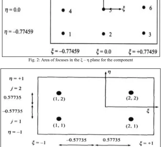
The location of points along ξ axis (abscissas) and corresponding weighing coefficients for different number of sampling points are given in Table 1.. It should be remembered that m sampling points a polynomial of degree (2m-1) can be integrated exactly.
Table – 1
Abscissand weight coefficient
n
i
wi
(1) (2) (3)
1 0.00000 2.00000 2 0.57735 1.00000 3 0.77459
0.00000
0.55555 0.88888 4 0.86113
0.33998
0.34785 0.65214 5
0.90617
0.53846 0.00000
Fig. 2: Area of focuses in the ξ – η plane for the component
Fig. 3: Area of joining focuses for straight components
VI. ANSYS
ANSYS programming is a capable and adaptable universally useful limited component investigation and computational liquid elements bundle utilized for structural building Mechanical building, electrical designing, physis and science reproductions. ANSYS is a broadly useful limited component displaying bundle for numerically tackling a wide assortment of issues in building, specifically:
1) Static/unique auxiliary investigation ( both direct and non-straight) 2) Fluid investigation Laminar and turbulent stream
3) Acoustic investigation 4) Electromagnetic investigation
5) Thermal investigation conduction, convection , radiation etc.
Element Name PLANE182 Input Nodes
I, J, K, L Degrees of Freedom
UX, UY Real Constants
R1,R2
R1- None, if KEYOPT (3=0,1,2) Thickness, if KEYOPT(3)=3 R2 - None, if KEYOPT(1)=0
Hourglass Stiffness Scaling factor, if KEYOPT(1)=1 (1.0 by default or if set to 0.0)
Material Properties
EX, EY, EZ, (PRXY, PRYZ, PRXZ or NUXY, NUYZ, NUXZ), ALPX, ALPY,ALPZ, DENS, GXY, DAMP Surface Loads
Pressures
face 1 (J-I), face 2 (K-J), face 3 (L-K), face 4 (I-L) Body Loads
Temperatures --
T(I), T(J), T(K), T(L), T(M), T(N), T(O), T(P) when KEYOPT(1) = 0 T(I), T(J), T(K), T(L), T(M), T(N) when KEYOPT(1) = 1 Special Features Plasticity, Stress stiffening, Large deflection, Large strain
KEYOPT(1) 0 - Full integration with B-bar method
1 - Uniform reduced integration with hourglass control KEYOPT(3) 0 - Plane stress
1 – Axisymmetric
2 - Plane strain (Z strain = 0.0) 3 - Plane stress with thickness input
Output Data
The solution output associated with the element is in two forms:
nodal displacements included in the overall nodal solution
additional element output. Several items are illustrated.
The element stress directions are parallel to the element coordinate system. A general description of solution output.
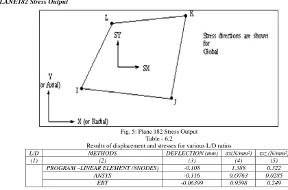
PLANE182 Stress Output
Fig. 5: Plane 182 Stress Output Table - 6.2
Results of displacement and stresses for various L/D ratios
L/D METHODS DEFLECTION (mm) σx(N/mm²) τxz (N/mm²)
(1) (2) (3) (4) (5)
PROGRAM –LINEAR ELEMENT (8NODES) -0.108 1.388 0.322
ANSYS -0.116 0.O763 0.0285
PROGRAM –LINEAR ELEMENT (4NODES) -0.1802 1.42 0.3134
ANSYS -0.238 1.44023 0.080
EBT -0.124997 1.199 0.269
Variation of Shear Stress at Mid Span of the Beam
Fig. 6: Shear Stress for curve for L/D=1
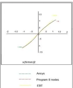
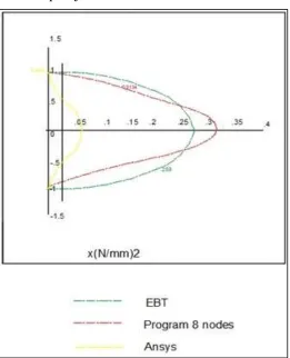
Variation Showing Flexural Stress near the Mid Span of the Beam
Variation of Flexural Stress near the Support of the Beam
Fig. 8: Flexural Stress curve for L/D=1
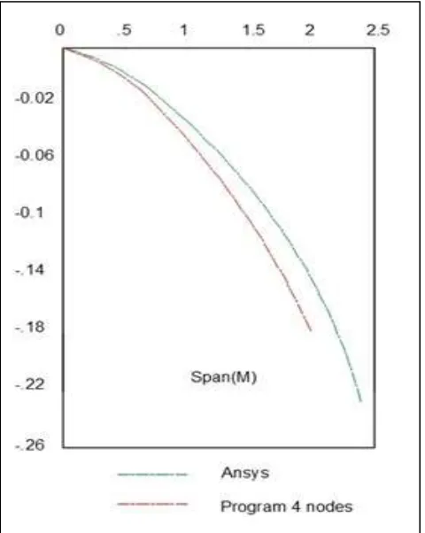
Graph showing deflection at the center line of the Beam
Graph Showing Deflection at the Center Line of the Beam
Fig. 10: Deflection curve for L/D=1
Variation of Shear Stress at the Mid-Span of the Beam
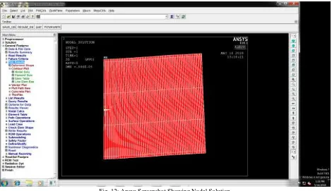
Fig. 12: Ansys Screenshot Showing Nodal Solution
VII. CONCLUSION
For displacement in regular and fine work, Plane, 182 and 183 and EBT comes about are near investigative solution, for utilize, so for this situation FEM is smarter to utilize. By an indistinguishable reason from FEM is recommended for normal and shear stresses. FEM is prescribed and better for use to solveplane issues. The beam of various L/D proportions are broke down by FEM program and ANSYS 2D investigation. Results got are contrasted and each other. From the outcomes conclusions are made and are as per the following
1) Deflection qualities given by EBT are significantly less than the qualities given by FEM program and ANSYS if there should arise an occurrence of rectangular deep beam
2) From the outcomes given by FEM program, ANSYS it is discovered that the flexural stress distribution in deep beam isn't direct as if there should be an occurrence of slim beams, however EBT gives the flexural stress distribution as straight for deep beam.
3) EBT gives the greatest shear stress at the inside line of the beam, yet in deep beams the most extreme shear stress is underneath the middle line of the beam
4) It is watched that the impartial pivot moves descending
REFERENCES
[1] Godbole P. N. (2013) “Introduction to Finite Element Method”, Page No. 23-184 I. K. Publishing House Pvt. Ltd. New Delhi Page [2] NiranjanB.R. and Patil S. S. (2012), “Analysis of Deep Beam By Finite Element Method” , IJMER VOL. 2, Issue 6.
[3] Yuwaraj M. Ghugal And Rajneesh Sharma (2011) “A refined shear deformation theory for flexure of thick beams”, Latin AmericanJournal of Solids and Strures Vo1. 8183-195.
[4] Mahdy and O. Sh. Farhan, A. A. A1- Azzawi 1, A. H. (2010) “Finite element analysis of deep beams on nonlinear elastic foundations”, Journal of the Serbian Society for Computational Mechanics, Vo1. 4, No. 2, pp. 13-42
[5] MuziburRahman, ReazAhmed S. (2008) “Toward The Exact Elasticity Solution Of A Deep Beam With Guided Ends”, Proceedings of the 4th BSME-ASME International Conference on Thermal Engineering 27-29 Dhaka, Bangladesh.
[6] ANSYS 12 Manual (2007), “Element References”, Ansysln.,
[7] Lawrence A, Soltis (1999) StructuralAualys Equations Chapter & Mood Handbook pg 463 U.S. Depositional of Agrieullure, Forest Products Laboratory, Madison, WI.
[8] Maki A.C. and Kuengi E.W (1965) Dihechou and stresses in tapered wood beams Res .pa1 FPL-RP-34, U.S. Depositional of Agrieullure, Forest Products Laboratory, Madison, WI Li Chow, Harry D. and Winter G.
[9] Yoo, T. M; Doh, J. H., and Guan, H. (2004) Experimental work on Reinforced and Prestressed Concrete Deep Beans with Various Web Openings. Griffith school of Engineering, Griffith University Gold Coast Campus, Queensland, Australia.
[10] Kong, F. K; and Chemrouk, M. (2002) Reinforced concrete deep beans. University of Newcastle Upon Yyne
[11] Sciarmmarella, C. A. (1963). Effect of holes in deep beams with reinforced vertical edges”, Engineering progress, University of Fla, 17, No. 12.
[12] Singh, R., Ray, S. P. and Reddy, C. S. (1980). Some tests on reinforced concrete deep beams with and without opening in the web, The Indian concrete journal, vol. 54, No. 7, Pp. 189 – 194.