Robust PID Controller Tuning for a Networked
Control System with Delay
Vikas Chandra Panigrahi Anirudh Mudaliar
ME Scholar Assistant Professor
Department of Electronics & Telecommunication Engineering Department of Electronics & Telecommunication Engineering
SSTC, Bhilai, India SSTC, Bhilai, India
Abstract
This paper presented a robust PID controller design for time delay system. This controller will be utilizing the gain-phase margin method; a specification-oriented parameter region in the parameter plane that characterizes all admissible controller coefficients sets can be obtained. Tuning of a PID controller refers to the tuning of its various parameters (P, I and D) to achieve an optimized value of the desired response. The basic requirements of the output will be the stability, desired rise time, peak time and overshoot. A compromise between the performances of the system with Ziegler-Nichols method is also included. Here we are measuring the plant response with and without delay condition with respect to original reference signal. Small modeling error is encountered and it is gradually detuned to a PID controller.
Keywords: Delay, Networked Control System, PID Controller, Ziegler-Nichols
________________________________________________________________________________________________________
I. INTRODUCTION
In Control system any quantity of interest in a machine, instrument is maintained or altered with a desired manner [3]. Control system implementation uses point-to-point communication architecture for long time. But there is a limitation in point-to-point architecture due to expanding physical setups and functionality [1]. Hence, these system are no longer suitable to meet new requirements such as modularity, decentralization of control, integrated diagnostics, quick and easy maintenance, and low cost. But new system called networked control systems (NCSs) are evolved due to advance technology network availability results in giving network facilities to Control system [12]. The major advantages of these systems are modular and flexible system design, simple and fast implementation, and powerful system diagnosis and maintenance utilities [3].
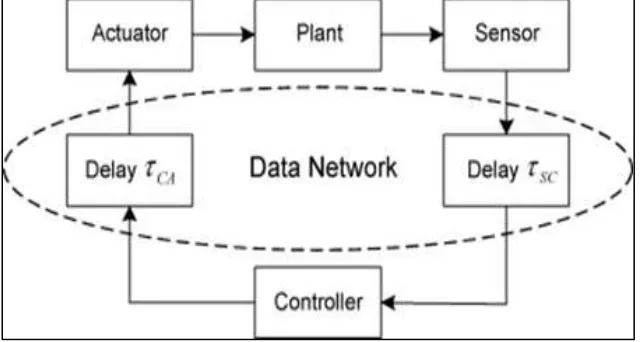
There are two general NCS configurations Direct and Hierarchical Structures. In Hierarchical Structure approach Fig. 1 the plant is controlled by its own remote controller at remote station.
Fig. 1: Networked Control System Configuration.
II. DELAYS IN NETWORKED CONTROL SYSTEM
Fig. 2: General NCS Configuration and Network Delays for NCS Formulations
As the use of computer networks grows rapidly applications, such as networked control systems (NCS), have emerged. NCS suffer from varying time-delays that bring new problems to the control loop [3]. The problem is that the network induces varying time delays into the control loop, which have to be taken into account in the control design [2].
Fig. 2 shows network delays in the control loop, where r is the reference signal, u is the control signal, y is the output signal, k is the time index and T is the sampling period.
Delay Characteristics
The delay of data transmission between the units of NCS is one of the important problems of NCS .due to This delay some data packages spoiled or completely get lost. That is, the signals are weakened. The network – induced delay appears from two main parts as sensor-controller and controller-actuator. The control systems constructed without considering this delay have a low performance and Reliability.
Effects of Delays In-The-Loop
Performance degradation
Delays in a control loop are widely known to degrade system performances of a control system, so are the network delays in a Network Control System.
Destabilization
Delays in-the-loop including network delays in an NCS can destabilize the system by reducing the system stability margin. Depending on the technology used for making AVR.
The time delays in the NCS may deteriorate the system performance and cause the system instability. Therefore, it is necessary to design a controller which can compensate for the time delays and improve the control performance of the NCS. The main aim in NCS environment of the control system is to maintain Quality of Performance (QoP) of the control system irrespective of the delays in the network. The system should be enough strong to compensate the delay induced by the network.
III. PID CONTROLLERS IN NCS
The PID controllers have been successfully applied to many industrial control systems. The robustness of systems mainly depends on the Gain margin and phase margin. In this paper, the previous achievement is extended to the non-minimum phase plant containing an uncertain delay time with specifications in terms of gain and phase. The gain-phase margin tester method is used to test the stability bounder y in the parameter plane for any given gain or phase margin specifications.
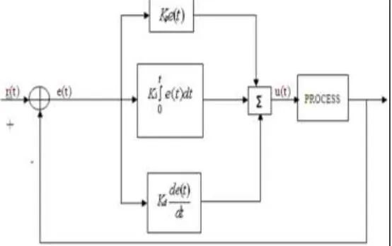
PID control logic is widely used in the process control industry. PID controllers have traditionally been chosen by control system engineers due to their flexibility and reliability. P-I-D controller has the optimum control dynamics including zero steady state error, fast response (short rise time), no oscillations and higher stability. Fig. 3 shows the block diagram of an PID controller
PID controller equation is given by
𝑢(𝑡) = 𝐾𝑝𝑒(𝑡) + 𝐾𝑖∫ 𝑒(𝑡)𝑑𝑡 + 𝐾𝑑 𝑡
0
𝑑𝑒(𝑡) 𝑑𝑡
Where 𝐾𝑝 represents the proportional gain, 𝐾𝑖 represents the integral gain, and 𝐾𝑑 represents the derivative gain, respectively. By tuning these PID controller gains, the controller can provide control action designed for specific process requirements.
Various system performances resulting from the tuning of the adjustable parameters can be realized completely. PID controller with coefficients selected from the obtained parameter area stabilizes the non-minimum phase time delay systems with pre-specified safety margins. Especially when the delay time is uncertain, this method works well.
The objective in every PID controller is to find the optimal tuned parameter of Kp, Ki and Kdwhich together gives the best desired response of the process under concern. There are many tuning formulas like Cohen-Coon formula, Wang- Juang-Chen formula, formula can be used for tuning the PID controller gains. Ziegler-Nichols’s step reaction curve method and closed loop cycling method are the two most popular tuning rules which are performed under proportional control around the nominal operating point.
IV. TUNING OF PID PARAMETERS
Tuning of a PID controller refers to the tuning of its various parameters (P, I and D) to achieve an optimized value of the desired response. The basic requirements of the output will be the stability, desired rise time, peak time and overshoot. Different processes have different requirements of these parameters which can be achieved by meaningful tuning of the PID parameters.
Ziegler–Nichols Rules for Tuning PID Controllers
There are two methods called Ziegler–Nichols tuning rules: the first method and the second method. First Method
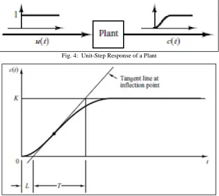
In this method we find experimentally the response of the plant for a unit-step input, as shown in Fig.4 If the plant involves neither integrator(s) nor dominant complex-conjugate poles, then such a unit-step response curve may look shaped, that S-shaped curve shown in Fig.5
Fig. 4: Unit-Step Response of a Plant
Fig. 5: S-Shaped Response Curve
Table - 1
Ziegler–Nichols Tuning Rule Based On Step Response Of Plant Type of Controller 𝐾𝑝 Ki 𝐾𝑑
P 𝑇
𝐿 ∞ 0
PI 0.9𝑇
𝐿 𝐿
0.3 0
PID 1.2𝑇
𝐿 2L 0.5L
𝐶(𝑠) 𝑈(𝑠)=
𝐾𝑒−𝑡𝑠
𝑇𝑠 + 1
Ziegler and Nichols provided the set values of Kp , Ki and Kd according to the formula shown in Table 1 Notice that the PID controller tuned by the first method of Ziegler–Nichols rules Gives
𝐺𝑐(𝑠) = 𝐾𝑝(1 +
1 𝑇𝑖𝑠
+ 𝑇𝑑𝑠)
= 1.2𝑇 𝐿(1 +
1
2𝐿𝑠+ 0.5𝐿𝑠)
= 0.6𝑇(𝑠 + 1 𝐿)2 𝑠
Thus, the PID controller has a pole at the origin and double zeros at 𝑠 = −1
𝐿 Second Method
In this second method first we set Ki = ∞ and Kd = 0. Using the proportional control action only, increase Kp from 0 to a critical value Kcr at which the output first exhibits sustained oscillations. If the output does not exhibit sustained oscillations for whatever value Kp may take, then this method does not apply. Thus, the critical gain Kcrand the corresponding period Pcrare experimentally determined (shown Fig.6). Ziegler and Nichols suggested that we set the values of the parameters Kp, Ki and Kd according to the formula shown in Table 2
Fig. 6: Sustained Oscillation With Period 𝑃𝑐𝑟(𝑃𝑐𝑟 Is Measured In Sec.)
Table - 2
Ziegler–Nichols tuning rule based on critical gain 𝐾𝑐𝑟and critical period 𝑃𝑐𝑟 (second method) Type of Controller 𝐾𝑝 Ki 𝐾𝑑
P 0.5𝐾𝑐𝑟 ∞ 0
PI 0.45𝐾𝑐𝑟
1
1.2𝑃𝑐𝑟 0
PID 0.6𝐾𝑐𝑟 0.5𝑃𝑐𝑟 0.125𝑃𝑐𝑟
The PID controller tuned by the second method of Ziegler–Nichols rules gives :
𝐺𝑐(𝑠) = 𝐾𝑝(1 +
1 𝑇𝑖𝑠
+ 𝑇𝑑𝑠)
= 0.6𝐾𝑐𝑟(1 +
1 0.5𝑃𝑐𝑟𝑠
+ 0.125𝑃𝑐𝑟𝑠)
= 0.075𝐾𝑐𝑟𝑃𝑐𝑟
(𝑠 +𝑃4
𝑐𝑟) 2
𝑠
Thus, the PID controller has a pole at the origin and double zeros at 𝑠 = − 4
Ziegler–Nichols tuning rules have been widely used to tune PID controllers to control different processes where the plant dynamics are not precisely known. Ziegler–Nichols tuning rules can be applied to plants whose dynamics are known [13].
V. SIMULATION RESULTS
Here we are designing a controller to deals with the instability introduce due to time delay for non- minimum phase system. The plant transfer function with time delay as shown below
𝑝𝑙𝑎𝑛𝑡 𝑡𝑟𝑎𝑛𝑠𝑓𝑒𝑟 𝑓𝑢𝑛𝑐𝑡𝑖𝑜𝑛 = 𝐴𝑥 𝑠3+ 𝐴
2𝑠2+ 𝐴1𝑠 + 𝐴0
𝑒−𝑇𝑠
Where T is the time delay. By using second order approximation the time domain and frequency domain specifications are converted as interval gain margin and phase margin. Hence the PID controller connected in series with the plant to achieve the specification of 5 𝑑𝐵 ≤ 𝐺𝑀 ≤ 10 𝑑𝐵 and 30° ≤ 𝑃𝑀 ≤ 60°.
Fig. 7: Block Diagram Of A Typical PID Control System.
Fig 7 shows the typical PID controller. Where controller GC(s) connected in series with plant GP(s) and D(s) is external disturbance. An error-actuated PID controller has the general transfer function
𝐺𝐶(𝑠) = 𝐾𝑃+
𝐾𝐼
𝑠 + 𝐾𝐷𝑠
The output is the simulation result obtained with the help of MATLAB at different plant conditions.
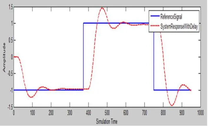
Fig. 8: System response with delay and absence of controller
Fig. 9: System response with delay and in presence of PID controller
Above figure shows the system response with PID controller. It is clear from fig.9 the system response has improved rise time as compare to system without controller. From the figure it is clear that the amplitude of maximum peak, maximum overshoot is more than the 1.5.
The response of the system is more accurate if the value of PID parameter is closure to the stability boundary.
Fig. 10: (a) Output of PID Controller (b) Magnitude and (c) Phase Response at 𝐾𝑝= 0.2 and KI = 2
Fig. 11: (a) Output of PID Controller (b) Magnitude and (c) Phase Response at Kp = 0.3 and Ki = 1.5
This figure shows the system response in the case of 𝐾𝑝 = 0.3 and 𝐾𝑖 = 1.5 . In this case system has moderate overshoot and lees settling time as compare to fig. 10.
Fig. 12: (a) Output of PID Controller (b) Magnitude and (c) Phase Response at 𝐾𝑝= 0.1 and 𝐾𝑖 = 1
VI. CONCLUSION AND FUTURE SCOPE
P-I-D control and its variations are commonly used in the industries due to their high stability zero steady state error and improved rise and overshoot. The desired closed loop performances, such as fast response, zero steady state error and less overshoot are achieved through incorporation of P, I and D actions respectively. By using Ziegler – Nichols tuning method we implemented the robust PID controller. This makes the system performance satisfactory with delay.
But it is very difficult to reduce the effect of delay on the system performance. So this paper also opens up work to reduce the difficulties while using this robust PID controller. This paper also opens scope for designing of robust PID controller to control plant with uncertainty and delay for closed loop unity feedback system.
REFERENCES
[1] N. Hohenbichler, J. Ackermann, “Synthesis of Robust PID Controllers for Time Delay System”, IEEE Publication, pp- 432-437, (2007).
[2] Takaaki Hagiwara, Kou Yamada, Iwanori Murakami Yoshinori Ando and Tatsuya Sakanushi “A Design Method For Robust Stabilizing Modified PID
Controllers For Time-Delay Plants With Uncertainty”, International Journal of Innovative Computing, Information and Control, Volume 5, Number 10(B), October 2009.
[3] Mikael Pohjola, Lasse Eriksson and Heikki Koivo “Tuning of PID Controllers for Networked Control Systems”, IEEE Publication, pp- 4244-0136,(2006).
[4] Yifei YANG, Huangqiu ZHU, “Robust Stability Regions of PID Parameters for Uncertainty Systems with Time Delay Using D-partitionTechnique”,
Journal of Computational Information Systems 9: 20,pp 8227-8234 (2013).
[5] Xavier Litrico, Didier Georges, “Robust continuous-time and discrete-time flow control of a dam- driver system. 2ndController design”,IEEE Publication
pp- 829-846(2004).
[6] P. V. Gopi Krishna Rao, M. V. Subramanyam, K. Satyaprasad, “Model based Tuning of PID Controller”, Journal of Control & Instrumentation Volume 4,
Issue 1, ISSN: 2229-6972,pp- 16-22(2013).
[7] KarimSaadaoui, Sami Elmadssia and Mohamed Benrejeb, “Stabilizing PID Controllers for a Class of Time Delay Systems”, Automatica, Volume 41, pp-
141-158 (2003).
[8] Ari Ingimundarson, Stefan Solyom, “On A Synthesis Method For Robust PID Controllers For a Class Of Uncertainties”, IEEE publication(2004).
[9] Tao Liu, DanyingGu, Weidong Zhang, “A H infinity design method of PID controller for second-order processes with integrator and time delay”,
Proceedings of the 42nd IEEE Conference on Decision and Control Maui,Hawaii USA, pp- 6044-6049 , (2003).
[10] M. Shamsuzzoha, JongpalJeon, Moonyong Lee, “Improved Analytical PID Controller Design for the Second Order Unstable Process with Time Delay”,
ESCAPE17, elevesr, (2007).
[11] Ahmed Bensenouci “PID Controllers Design for a Power Plant Using Bacteria Foraging Algorithm” 978-1-4577-0069-9/11/$26.00 ©2011 IEEE
[12] L. Eriksson, “A PID Tuning Tool for Networked Control Systems”, WSEAS Transactions on Systems, Vol. 4, Issue 1, pp. 91-97, (2005).
[13] Hang Wu, Weihua Su, Zhiguo Liu PID Controllers: design and tuning methods, IEEE publication pp-808-813 (2014)
[14] Kiyong Kim, Richard C. Schaefer. “Tuning a PID Controller for a Digital Excitation Control System” IEEE Transactions On Industry Applications, Vol.