ISSN (Online): 2320-9364, ISSN (Print): 2320-9356
www.ijres.org Volume 3 Issue 6 ǁ June 2015 ǁ PP.66-73
Synthesis and Characterization of Silica-Nickel Nanocomposite
through sol-gel route
A.K.Pramanick
Department of Metallurgical & Material Engineering Jadavpur University Kolkata-700032, India
.
Abstract
: The optimum combination of experimental variables- temperature, time of heat treatment under nitrogen atmosphere and amount of Ni-salt was delineated to find the maximum yield of nanophase Ni in the silica gel matrix. The size of Ni in the silica gel was found in the range 35 and 61nm. In the last two decades synthesis, characterization and understanding a material with lower dimensions have become the most interesting area of research due to their novel properties and potential applications in different fields.Keywords
: Sol-gel; Ni, Nano phase, NanocompositesI.
Introduction
The synthesis and characterization of nanostructured materials have recently been studied world over because of their novel properties and potential applications in many fields and effort has been given for basic understanding(1-3) . Many methods have been used of which sol-gel technique is more versatile(4-6) .This technique has been exploited to synthesize metal insulator nanocomposites which have possible applications in optical switches and single electron transistor (7), fine soft magnetic materials(8) , microwave absorbing and shielding materials( 9) , and super paramagnet(10)etc. The kinetics of the reduction of the metal salts in silica gel matrix has been widely studied. Detailed kinetic analysis have been carried out ,for in situ reduction of transition metal salts in silica(11) and silica- alumina gel matrix(12) to understand the mechanism of reduction and to compute the activation energy. This would help to control and tailor make the nanocomposites. The amount of metal along with other morphological characterization would influence the property (13).
II.
Experimental Procedure
The silica-Nickel gels were prepared through the hydrolysis followed by poly-condensation of tetraethyl-orthosilicate (TEOS) in water/ethanol solution under acidic condition. In this typical process, each one with TEOS:H2O:C2H5OH ratio of 1:1:2 by volume respectively is prepared as follows. First a homogeneous solution is prepared with 1 ml of distilled water, containing required amount of NiCl2, 100% excess glucose over stoichiometric requirement of complete reduction of NiCl2, 5 ml of ethyl alcohol; and 4ml of distilled water under stirring. A second homogeneous solution of 5 ml C2H5OH and 5 ml tetraethyl orthosilicate(TEOS) is also prepared in a beaker under constant magnetic stirring. The first solution is added drop wise to the second one under continuous stirring with a magnetic stirrer followed by the addition of a few drops of 8 (N) HCl as a catalyst to the solution. The resulting solution is left for gelling at room temperature. We prepare the samples for 5 Wt%, 10 Wt%, 15 Wt%, 20 Wt%, of nickel with 100% excess glucose over that required for the complete reduction of NiCl2 .
The heat treated samples were ground and passed through 400 mesh and XRD patterns of these were taken using Cu Kα monochromatic radiation in Regaku make Ultima III, XRD instrument. The TEM images have been recorded with a JEOL JEM 1010 microscope. The sizes of nanoparticles from each TEM image were measured and the corresponding size histogram have been reaaised using specific software.
III.
Results and Discussion:
The insitu reduction of NiCl2 in silica gel occurs as follows as reported elsewhere in details [5] C6H12O6 = 6C + 6H2O ↑
C + H2O = CO↑+ H2↑ H2 + NiCl2 = Ni +2HCl↑.
hardly any oxidation.
Fig1-4, represent the XRD patterns of the silica gel samples containing 5wt%,10wt%, 15Wt% and 20wt% Ni heat treated at 550oC for 12 minutes. In each figure, peaks corresponding to Ni are marked.
Scherrer formula, given below has been used to compute the crystallite size of nickel, t = 0.9λ/Bcosθ
Where,
t is the average crystallite size in A0
B is the width of the peak at half maximum in radian, and λ is the wave length of X-ray in Å.
The highest intensity peak in each case has been used to compute the crystallite size of the Ni for Silica-5 wt% Ni, 10 wt% Ni, 15 wt% Ni and 20 wt% Ni nanocomposite respectively.
Fig. 5-8 represent the TEM image of the silica - 5 wt% Ni, 10 wt% Ni, 15 wt% Ni, 20 wt% Ni nanocomposite respectively, heat treated at 550oC for 12 minutes in N2 atmosphere. The Nickel particles of nanometric dimension are clearly visible in TEM image (Figs). It is to be noted from the TEM images that agglomeration is more for when the Nickel content is more, e.g. 10, 15 & 20 wt%. This is probably the reason why the image sizes estimated from TEM for these samples are significantly larger than those which are measured by scherrer formula. However, in TEM images for all the samples 5wt% to 20wt%Ni there is the distribution of size. This is because the nickel nuclei which are formed at the longer stage through reduction can grow for longer time. The particle size of nickel was calculated (ref. Scherrer formula) and directly measured from the TEM images tabulated below in the table 1. From the table it is observed that the particle sizes of Nickel changes from 35 to 61 nm as the Nickel content in the Silica –Nickel nanocomposites increases from 5wt% to 20wt% of Ni.. The value of Sinθ/λ the hump in each of samples (ref. Fig 1- 4 ) is 0.116, very close to 0.12 which is attributed to amorphous silica[13]. This is plausibly due to slow kinetics of crystallization of amorphous silica arising out of lower reduction temperature for a shorter period of time. It is observed that with the increase in the content of Nickel, the relative amount of silica decreases, as a result of which the height of silica hump reduces & becomes negligible small for 20wt% Ni sample (ref. Fig.4).
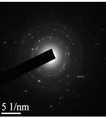
Fig.9-12 represents the SAED (Selected Area Electron Diffraction) patterns for the above samples. From this fig we compute compute the interplaner spacing and compare with the standard dhkl of Nickel. Table 2 shows that the agreement between the standard and experimental dhkl are good. This suggest that dhkl of Nickel and this is agree mental with the findings of XRD( Ref. JCPDS)
Fig. 13-16 represents the lattice image. The interplanar spacing (.21nm) matches reasonably well with the standard value of metallic nickel(.202nm) (JCPDS Card no.—1051) This further confirms the presence of metallic Nickel.
0 20 40 60 80 100
50 100 150 200 250 300 Ni Ni Inten sit y (a.u ) 2theta(degree)
0 20 40 60 80 100 50 100 150 200 250 300 350 400 Ni Ni Int ensit y (a.u) 2theta(degree)
Fig 2 XRD pattern of sample containing Silica-10wt% Ni heat treated at 550oC for 12 minutes in nitrogen atmosphere.
0 20 40 60 80 100
50 100 150 200 250 300 350 400 Ni Ni Ni Inten sit y (a.u ) 2theta(degree)
Fig 3 XRD pattern of sample containing Silica -15wt% Ni heat treated at 550oC for 12 minutes in nitrogen atmosphere
20 30 40 50 60 70 80
0 200 400 600 800 1000 1200 1400 1600 1800 2000 Ni Ni Ni Ni Int ens it y (a. u) 2theta(degree)
Fig. 5 TEM image of sample containing Silica - 5 wt% Ni heat treated at 550oC for12 minutes in nitrogen atmosphere
Fig. 6 TEM image of sample containing Silica -10 wt% Ni heat treated at 550oC for12 minutes in nitrogen atmosphere
Fig. 7. TEM image of sample containing Silica -15 wt% Ni heat treated at 550oC for12 minutes in nitrogen atmosphere
Ni
SiO
2Ni
SiO
2SiO
2Fig. 8 TEM image of sample containing Silica - 20 wt% Ni heat treated at 550oC for 12 minutes in nitrogen atmosphere
Fig. 9 SAED pattern of sample containing Silica - 5 wt% Ni heat treated at 550oC for 12 minutes in nitrogen atmosphere
Fig. 10 SAED pattern of sample containing Silica - 10 wt% Ni heat treated at 550oC for 12 minutes in nitrogen atmoshere
SiO
2
Fig. 11 SAED pattern of sample containing Silica- 15 wt% Ni heat treated at 550oC for12 minutes in nitrogen atmosphere
Fig. 12 SAED pattern Lattice image of sample containing Silica -20 wt% Ni heat treated at 550oC for 12 minutes in nitrogen atmosphere
Fig. 14 Lattice image of sample containing Silica - 10 wt% Ni heat treated at 550oC for 12 minutes in nitrogen atmosphere
Fig. 15 Lattice image of sample containing Silica-15 wt% Ni heat treated at 550oC for 12 minutes in nitrogen atmosphere
Table 1 contains the particle sizes of Nickel in Silica-Nickel Nanocomposites
Samples Nickel crystallite size from
XRD
Nickel particle size from TEM image
Silica -5wt% Ni 35nm 36nm
Silica -10wt% Ni 40nm 39nm
Silica -15wt% Ni 52nm 53nm
Silica -20wt% Ni 60nm 61nm
Table 2 contains interplaner spacing and compare with the standard dhkl of Nickel
Samples d (111) value
from XRD
d value from TEM lattice image
d (111) value
from SAED pattern
d (111) value from JCPDS Card No. 03-1051
Silica -5wt%Ni 0.204 nm 0.213 nm 0.218 nm 0.202 nm
Silica -10wt% Ni 0.203 nm 0.212 nm 0.211 nm 0.202 nm
Silica -15wt% Ni 0.204 nm 0.206 nm 0.207 nm 0.202 nm
Silica- 20wt% Ni 0.204 nm 0.207 nm 0.209 nm 0.202 nm
IV.
Conclusions
1. Silica-Nickel Nanocomposites have been successfully synthesized via sol-gel route through insitu reduction at 550oC for different percentage of Nickel.
2. The particle size of Nickel computed by scherrer is in the nanometric levelas observed from the X-ray diffraction patterns. It is observed that the Nickel particle size ranging from 35 to 61 for different Nickel content in the silica matrix from 5wt% to 20wt% is in good agreement with obtained from TEM analysis.
V.
Acknowledgement
:A.K.Pramanick appreciates the University Grants Commission (UGC), the Government of India for financial assistance under the University with the ‘potential for excellence’ programme. Discussion with Professor G.C.Das, Professor M.K.Mitra led to improvement of this paper.
References
[1] Gao Y.Q, Bando Y, Nature 415, 599. 2002[2] Gorla C.R,Emanetoglu N.W, Liang S, Mago W.E, Lu Y, Wraback M, M..Shen M, Journal of Applied Physics. 85, 2595. 1999 [3] Aldal J, Rico- Gracia J.M, Lopez-Alonso J.M, Boreman S Nanotechnology 16, 230. 2005
[4] Rao C.N.R 1993 Material Science and Engineering B 18, 1
[5] Das G.C, Basumallick A, Mukherjee S, 1990 Bulletin of Material Science, 13,255-258.
[6] Mallick S,.Das G.C,Mukherjee S, Mitra M.K, 2006 Journal of Physics and Chemistry of Solids 67, 1792
[7] Yeshchenko,Oleg A, Dmitruk, Igor M, Alexeenko, Alexandr A, Dmytruk, Andriy M, 2008 Journal of physics and chemistry of solids. 69, 1615
[8] peng Kun, Zhou Lingping, Hu Aiping, Tang Yuanhong, and Li Deyi 2008 Materials Chemistry & Physics 3, 34 [9] Fonseca F.C, 2003 Applied physics A Materials Science & Processing, 76, 621.
[10] Basumallick A,Das G.C, Mukherjee S,1999 Thermochimica Acta 325, 167-170. [11] Roy S.K.,.Dey R,.Mitra A, Mukherjee S, Mitra M.K, Das G.C, 2007 27,725-728.
[12] Kafarov V, 1976 Cybernetic methods in Chemistry and Chemical Engineering Mir Pub. Moscow.