Simulation of Rolling Forming of Precision
Profile Used for Piston Ring based on LS_DYNA
Jigang Wu
Hunan University of Science and Technology/Hunan Provincial Key Laboratory of Health Maintenance for Mechanical Equipment, Xiangtan, 411201, China
Xuejun Li and Kuanfang He
Hunan University of Science and Technology/Engineering Research Center of Advanced Mine Equipment, Ministry of Education, Xiangtan, 411201, China
[email protected], [email protected]
Abstract—The rolling process of precision profile used for piston ring is simulated by large general-purpose explicit dynamic finite element analysis software ANSYS/LS_DYNA. The modeling of finite element models, the selection of material models and element types, the meshing of the model are introduced in detail. The rolling metal flow rulers of each pass are gained. The deformation of rolled piece and distribution of stress field are analyzed deeply. These can provide guidance for the design of forming roller and the optimization of process.
Index Terms—piston ring, precision profile, rolling forming, explicit dynamic finite element, numerical simulation
I. INTRODUCTION
Piston ring is one of the key parts of engine, and is often compared to the heart of engine. Meanwhile, piston ring is also an easy-to-break part and needs to be changed frequently, and billions of piston rings are manufactured in China each year. The dimension of piston ring is small and the requirements of dimensional accuracy and surface roughness are high. The piston ring is formed at last through more than twenty procedures such as turnery, milling and grinding and so on with cast iron material by traditional processing approach for a long time, and the production cost of piston ring is very high.
With the development of precision forming technology, the precision profile which is satisfied with the requirements of cross section shape and dimensional accuracy of the piston ring is produced by cold forming rolling technology in developed country, and then the precision profile is coiled into openings elliptic with specific shape by CNC forming machine, so the piston ring can be formed at once. The past more than twenty procedures can be reduced to several procedures, so not only the processing cost is reduced but also the product performance is improved. However, the machining and manufacturing of this precision profile is still a blank in our country, and in order to meet the production requirement of piston ring, the precision profile must be imported from abroad each year though the price of
oversea precision profile is high. Therefore, the localization of the precision profile has great significance.
During the cold forming rolling process, the law of plastic deformation of materials, the friction between roller and rolled piece, the change of material microstructure, the influence of rolling reduction rate, roller diameter and rolling speed and so on are very complex issues. In order to investigate the deformation law of metal materials in the rolling process, the experimental research method can provide accurate reference data for on-site production and it is in accord with actual production. But the cycle of the experimental research is longer because a lot of work must be done before the experiment, such as the preparation, field experiment and experimental results processing and so on. Moreover, because of the uncertainty of experiment, it is often difficult to resolve all the issues to be studied in one experiment, and at the same time the probability of the failure in the experiment is very high. Once the experiment failed, it will waste a lot of manpower and material resources. At the same time, the traditional experimental methods is difficult to deal with the rolling of precision profile which is related to the quantitative calculation of distributed variables such as metal flow and stress field and so on.
material properties on T-section ring rolling by three-dimensional elastic–plastic FE method [7]. Hua et al. established the three-dimensional FE model of plastic penetration in L-section profile cold ring rolling under ABAQUS software, and based on this model, the expanding rules of plastic zone in roll gap are revealed by FE simulation, and three deformation behaviors of L-section ring that exist in the rolling process are exposited [8]. Shuai et al. proposed a finite element model for simulating the formation process of shaped steel tube for driving shaft based on the deformation characteristics of Y type mill [9]. Chen et al. developed a comprehensive procedure to predict the degree of void closure using finite element analysis and neural net-work [10]. But until now, very few focused on the study of the simulation of rolling forming of the precision profile. The rolling process of precision profiles used for piston ring at the production is simulated with explicit dynamic finite element technology, and it can provide more accurate reference data for the design and optimization of rolling mill and the optimization of rolling process parameters.
II. MODELING OF ROLLING PROCESS
A. Explicit Dynamic Finite Element
The general form of finite element equation for dynamic analysis is shown as follows.
[ ]
M U{ }
&& +[ ]
C U{ }
& =[ ] [ ]
P − F (1) Where,{ }
U&& is acceleration array of whole nodes,{ }
U& is velocity array of whole nodes,[ ]
M is whole massmatrix,
[ ]
C is whole damping matrix, { }P is called asexternal node force array,
{ }
F is called as internal node force.Mathematically, formula (1) is a second order system of differential equations. If the balance of the object finite element system at t+ Δt moment is considered, the following equation will be obtained.
[ ]
t t{ }
[ ]
t t{ }
t t{ }
t t{ }
M +Δ U&& + C +Δ U& =+Δ P −+Δ F (2) Formula (2) is a nonlinear differential equation, and needs to be solved with implicit integral method. If formula (1) is constant coefficient system of differential equations, the velocity and acceleration can be represented approximately with displacement by any appropriate finite difference method, and the formula (1) can be changed to explicit linear system of equations whose unknown variables are t+Δt
{ }
U , and the t+Δt{ }
Ucan be worked out directly. If the balance of the object finite element system at t moment is considered, the idea will be realized. As to the moment t, formula can be written as follows.
[ ]
M t{ }
U&& +[ ]
Ct{ }
U& =t{ } { }
P −t F(3)
If the velocity and acceleration are represented approximately with displacement by any appropriate finite difference method, the formula (3) can be changed to explicit linear system of equations whose unknown
variables are t+Δt
{ }
U, and then the displacement of t+Δt
moment can be worked out directly. This solution method is called as explicit integral method. As to the dynamic analysis of elastoplasticity issue, an effective method is central difference method. The difference quotients of central difference method are as follows.
{ }
{ }
{ }
t 1 t t t t
U ( U U )
2 t
+Δ −Δ
= −
Δ
& (4)
{ }
{ }
{ }
{ }
t t t t t t
2
1
U ( U 2 U U )
t
+Δ −Δ
= − +
Δ
&& (5)
The formula (4) and (5) are substituted into formula (3), then
[ ]
[ ]
{ }
{ } { }
[ ]
{ }
{ }
[ ]
{ }
t t 2 t t
t t t t t
t
( M C ) U t ( P F )
2
t
M (2 U U ) C U
2 +Δ −Δ −Δ Δ + = Δ − + Δ − + (6)
Denoted as follows,
[ ] [ ]
[ ]
t t
K M C
2
Δ
= + (7)
{ } { }
[ ]
{ }
{ }
[ ]
{ }
t 2 t t t t t
t t
ˆ
R t ( P F ) M (2 U U )
t C U 2 −Δ −Δ ⎡ ⎤ = Δ − + − ⎣ ⎦ Δ
+ (8)
The formula (6) can be wrote as follows,
{ }
{ }
t t
t ˆ t ˆ
K +Δ U R
⎡ ⎤ =
⎣ ⎦ (9) The t t
{ }
U
+Δ
can be worked out directly according to formula (9).
The calculation of the central difference method is conditionally stable. In order to ensure the stability of the calculation, the time step Δt must less than critical time step Δtcr. The critical time step value is related to the
minimum natural vibration period of the object system
min
T . As to finite element analysis, Tmin is minimum vibration period of the finite element sets. Ordinarily, the
cr
t
Δ can be worked out with the following formula.
min cr
T t
Δ =
π (10)
In the finite element analysis of the plastic forming, ordinarily the time step Δt can be chose as follows.
cr
t t
Δ = ηΔ (11) Where, η is a coefficient which is less than 1.0, ordinarily can be choose from 0.5 to 0.8. In the real calculation, the critical time step Δtcr can be ascertained
approximately according to the element size. As to every element, the critical time step Δtcr can be calculated with the following formula.
e cr
L t
c
Δ ≤ (12) Where, the c is the propagation velocity of elastic wave, as to metal, c is calculated as follows.
2G(1 v) c
(1 2v)
− =
e
L is the nominal length of the element, and is related to the element types, and the value of Le can be selected
as the distance of two nodes which are closest in the element.
B. Establishment of Model
In order to enhance the confidence and accuracy of the simulation, the dimension of the geometric model is identified with the dimension of the production equipment in the produces field, and the rolling process is supposed to be reasonable as follows, all diameters of rollers are equal, the rotational speeds of rollers are same, and all rollers are drive roller, the mechanical properties of rolled piece are uniform, the rollers rotate at a constant angular velocity, the rolled piece moves to roller slit at a constant speed which is approach or equal to the peripheral speed of roller until the rolled piece is nipped into the roller slit, the rolling process is done depending on the friction force between the roller and the rolled piece.
The blank of the rolled piece is a round steel wire whose diameter is 2.7 mm, and the cross section of the precision profile is rectangle whose height is 1.5 mm and width is 3.5mm, so the blank is rolled by two pass process tandem rolling, the blank is rolled at two rollers rolling mill firstly to realize the thickness requirement of the precision profile basically, then the blooming piece is rolled at finished rolling at dislocation four rollers rolling mill, and then the formed precision profile is obtained.
The material of rolled piece is 50CrVA, its elastic modulus E is 206GPa, tangent modulus Etan is 90MPa, yield limit σs is 1127MPa, density ρ is 7850kg/m3, poisson ratio μ is 0.3. The material of roller is 9CrSi, its elastic modulus E is 206GPa, density ρ is 7850kg/m3, poisson ratio μ is 0.3. The diameter of the roller D is 120mm.
The rolling process is modeled, solved and analyzed by large general-purpose explicit dynamic finite element analysis software ANSYS/LS_DYNA. As to the selection of element types, the explicit block element SOLID164 is chosen for the rolled piece and the roller. As to the selection of material models, the roller can be treated as rigid roller because the deformation of the roller is small on the condition of cold rolling, so the rigid material model is chosen for the roller, and the Bilinear Kinematic (BKIN) material model is chosen for the rolled piece.
In ANSYS/LS-DYNA, the contact friction is based on Coulomb formula. The friction coefficient can be worked out with following formula.
DC v c d ( s d)e
− ×
μ = μ + μ − μ (14) Where μs is static friction coefficient, μd is dynamic
friction coefficient, DC is index attenuation coefficient, v is the relative velocity between the contact faces.
The maximum frictional force can be defined with viscous friction coefficient VC and the area of the contact region, the formula is shown as follows.
lim cont
F =VC A× (15)
The recommended viscous friction coefficient VC is as follows.
0
VC 3
σ
= (16)
In which, σ0 is the yield stress of the contact material. In order to avoid the oscillation in the contact, the contact damping coefficient VDC can be used to apply damping at the vertical direction of the contact faces. The VDC can be worked out with the following formulas.
crit
VDC 100
ζ = ζ (17)
crit 2m
ζ = ω (18)
slave master slave master
k(m m )
m m
+ ω =
+ (19)
{
slave master}
m=min m ,m (20) Ordinary, the value of the VDC is 20.
The symmetric penalty function contact algorithm is selected, and the contact type is Automatic Surface to Surface Contact, the static friction coefficient μs is 0.482,
the dynamic friction coefficient μd is 0.346, the viscoelasticity friction stress VC is 650.67MPa, the contact damping coefficient VDC is 20. The contacts between rolled piece and all rollers are defined respectively.
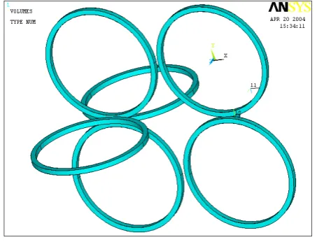
Since the roller is regarded as rigid roller, in order to reduce the element quantity and shorten the computation time, the solid roller is replaced with the roller surface generally at the modeling. So as to approximate the real production and reduce the element quantity, the real roller is simulated by a torus whose thickness and width are 5 mm, and the real rolled piece is simulated by a cylinder whose diameter is 2.7 mm and length is 5 mm. The geometrical model of two roller rolling mill and dislocation four rollers tandem rolling mill is shown in figure 1. The whole geometry model of two roller rolling and dislocation four rollers tandem rolling is shown in 1 (a), the roller arrangement of dislocation four rollers rolling mill is shown in 1 (b), the model of rolled piece is shown in 1 (c).
(b) Roller arrangement of dislocation four rollers rolling mill
(c) Model of rolled piece
Fig. 1 Geometrical model of two roller rolling and dislocation four rollers tandem rolling
C. Meshing of Model
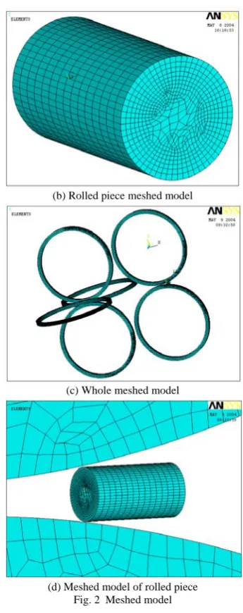
Mapped meshing method is used, element type is hexahedral element, and the meshing is done by manual sweep method. As to the roller, since the length of rolled piece model is quite short, only less than 1/4 arc of the roller contacts with the rolled piece during the simulation process. So as to reduce the element quantity and shorten the computation time, the whole roller is meshed into coarse grids, only 1/4 arc of the roller which will contact with rolled piece is fined, the subdivision number of the width direction is 5, the subdivision number of 1/4 arc of the roller is 100, element dimension is 2 mm, element number is 23710. As to the rolled piece, the lines at the length and the circle on end face are fined, and the subdivision number of the length direction is 15, the subdivision number of the circle on end face is 60, element dimension is 1 mm, element number is 8745. The meshed model is shown in figure 2, and one of roller meshed model is shown in 2 (a), the rolled piece meshed model is shown in 2 (b), the whole meshed model is shown in 2 (c), the meshed model of rolled piece is shown in 2 (d).
(a) Roller meshed model
(b) Rolled piece meshed model
(c) Whole meshed model
(d) Meshed model of rolled piece Fig. 2 Meshed model
III. ANALYSIS OF SIMULATION RESULT
The stress distribution nephogram and deformation of rolled piece of nipping stage, stable rolling stage and throwing steel stage in the first pass are shown in (a), (b) and (c) of figure 3 respectively. The stress distribution nephogram and deformation of rolled piece of nipping stage, stable rolling stage and throwing steel stage in the second pass are shown in (a), (b) and (c) of figure 4 respectively. The different color region in the stress nephogram of rolled piece corresponds to the different stress magnitude, the stress scaleplate on the right edge demonstrates the corresponding relationship between the color and the stress value by scientific notation, and the unit of the stress scaleplate is Pa.
A. Results Analysis of First Pass
but the element grids at the heart and both sides have not deformed obviously. The metals at top and bottom surface of the forehead of the rolled piece contact with the roller and are pressed by the roller, the end face of the forehead of the rolled piece is free surface, so the restraint to the metals deformation of the rolled piece is small. The metals at the heart and both sides of the rolled piece are not pressed by the roller so the deformation is small. The metal follows to the rule flowing to the place of smallest resistance, so the forehead of the rolled piece is rolled as obvious wedge shape. The stress of the rolled region at the forehead of the rolled piece and the region which contact with roller is bigger, the stress at the both sides of forehead and the region that is not rolled is smaller. The figure 3 (b) reveals that, the double swallow tail at the forehead of the rolled piece is more obvious than nipping stage, the contact region and it’s neighbor flow obviously and form 1/4 spheroid shape, the rolled region has been rolled to the shape of the pass, the element grids on the contact surface have been elongated in the length direction and have not been distorted obviously in the width direction, the element grids at the heart of the rolled region have been elongated in the width direction and have not been distorted obviously in the length direction, the element grids at both sides have not been distorted obviously. This indicates that, at the stable rolling stage, the superficial metals which contact with the roller mainly has the extend distortion in the length direction and the heart metals of rolled region mainly has the extend distortion in the width direction. Along with the advance of the rolling, big stress are distributed at the rolled region and the top and bottom surface which contact with roller. The figure 3 (c) reveals that, the forehead and the empennage of rolled piece have been rolled to the obvious double swallow tails, the center of the both sides of rolled piece have extruded slightly, the rolled piece has been rolled to the shape of the pass, the element grids at the heart of the rolled piece have been elongated and flattened in the width direction, the element grids at the both sides and contact surface have been elongated in the length direction, the deformations of all grids are synchronous. The elongation modulus of the rolled piece in length direction is 1.101, and in the width direction is 1.270, therefore the rolled piece has fiercer distortion in width direction than in length. The residual stress in the interior of the rolled piece which stem from the elastic restitution of the metals is 1.093 GPa.
(b) Stable rolling stage (c) Throwing steel stage Fig. 3 Stress nephogram of the first pass
B. Results Analysis of Second Pass
(a) Nipping stage
(b) Stable rolling stage
(c) Throwing steel stage Fig. 4 Stress nephogram of the second pass
IV. CONCLUSIONS
tandem rolling experiment is done at production field, the experiment results are identical with the simulation results very well, so plenty of time and the expense are saved. At the same time, it indicates that the explicit dynamic finite element can be used for the three dimension simulation of the cold rolling forming process of the precision profile very well.
ACKNOWLEDGEMENT
Financial support from CEEUSRO Special Plan of Hunan Province (2010XK6066), Aid Program for Science and Technology Innovative Research Team in Higher Educational Institutions of Hunan Province, Industrial Cultivation Program of Scientific and Technological Achievements in Higher Educational Institutions of Hunan Province (10CY008), Natural Science Foundation of Hunan Province (11JJ9016), Project Supported by Scientific Research Fund of Hunan Provincial Education Department (09C405), Ph.D. Start Fund (E50925), are gratefully acknowledged.
REFERENCES
[1] L.Z. Liu, X.H. Liu, and Z.Y. Jiang, “Strip Rolling
Simulation by the Dynamic Explicit FEM”, Journal of
Plasticity Engineering, vol.8, pp. 51-54, 2001.
[2] F.X. Diao, K.F. Zhang, “Dynamic explicit finite element analysis of springback of sheet V-bending”, Materials Science and Technology, vol.10, pp. 170-174, 2002. [3] H. B. Xie, H. Xiao, and G.M. Zhang, “Analysis of strip
rolling pressure distribution for different width by explicit dynamic FEM”, Journal of Plasticity Engineering, vol.10, pp. 61-64, 2003.
[4] D. Wu, X.M. Zhao, and J.C. Li, “Simulation of billet
rolling in oval roll-profile by FEM”, Journal of Plasticity Engineering, vol.10, pp. 57-60, 2003.
[5] H.S. Niu, X.M. Zhao, and D. Wu, “Profiled billet
deformation simulation of H-beam with slab by FEM”, Journal of Plasticity Engineering, vol.13, pp. 41-44, 2006. [6] L. Fan, N.L. Tan, and D.P. Shen, “FEA on Stress Field of
Rolling Element Bearing Based on Explicit Dynamics”, Journal of Beijing Jiaotong University, vol.30, pp. 109-112, 2006.
[7] L.Y. Li, H. Yang, and L.G. Guo, “Research on Interactive Influences of Parameters on T-shaped Cold Ring Rolling by 3D-FE Numerical Simulation”, Journal of Mechanical Science and Technology, vol.21, pp. 1541–1547, 2007.
[8] L. Hua, D.S. Qian, and L.B. Pan, “Deformation Behaviors and Conditions in L-section Profile Cold Ring Rolling”, Journal of Materials Processing Technology, vol.209, pp. 5087–5096, 2009.
[9] M.R. Shuai, S.B. Liu, and C.M. Gao, “Finite Element
Simulation of Cold Rolling Process of Shaped Steel Tube for Driving Shaft”, International Journal of Iron and Steel Research, vol.17, pp. 25-29, 2010.
[10] J. Chen, K. Chandrashekhara, and C. Mahimkar, “Void Closure Prediction in Cold Rolling Using finite Element
Analysis and Neural Network”, Journal of Materials
Processing Technology, vol. 211, pp. 245–255, 2011.
Jigang Wu, who was born on August 3, 1978 in Hunan province, received master degree in 2004 and Ph.D in 2008 from Wuhan University and Huazhong University of Science and Technology respectively, research field is advanced manufacturing technology, dynamics of machinery and fault diagnosis.
He has been working at Hunan University of Science and Technology since 2008, mainly engaged in theory and practice of teaching, scientific research. His paper works are: “Subpixel Edge Detection of Machine Vision Image for Thin Sheet Part”, China Mechanical Engineering (2009), “Research on Planar Contour Primitive Recognition Method based on Curvature and HOUGH Transform”, Journal of Electronic Measurement and Instrument (2010), etc.
Dr. Wu is a member of Hunan Province Instrumentation Institute. In recent years, he has presided two provincial research projects, obtained three provincial academic rewards, and published more than 10 academic papers.
Xuejun Li, male, born in 1969. He received Ph.D from Central South University in 2003. He is currently working at Hunan University of Science and Technology, China. His research interests include fault diagnosis, dynamic monitoring and control for electromechanical systems.