303 | P a g e
NUMERICAL ANALYSIS ON THERMAL ENERGY STORAGE TANK FILLED
WITH PHASE CHANGE MATERIAL
Uday Maruti Jad
1PG Student, Department of Mechanical Engineering
Rajarambapu Institute of Technology Rajaramnagar, India.
Jaduday96@gmail.com
Dr. Abhijeet P. Shah
2Professor, Department of Mechanical Engineering
Rajarambapu Institute of Technology Rajaramnagar, India
Abhijeet.shah@ritindia.edu
Abstract—The use of a thermal energy storage system
with phase change materials (PCMs) is an efficient way of energy storage. PCMs are generally used in thermal energy storage systems for heat pumps, solar systems, spacecraft thermal applications etc. The purpose of this study is to identify effect of geometrical changes on the melting process of PCM. Computational fluid dynamic (CFD) is used to analyze phase change process. Thermal energy storage tank consists of a vertical tube in tube geometry where outer tube consist phase change material and inner pipe carrying hot fluid. Paraffin is used as latent heat storage material. Further, the paper describes the effect of inlet temperature of heat transfer fluid on the phase change process. Result shows that charging time is 2.56% less required for conical shaped storage system rather cylindrical shaped system.
Keywords— Phase Change materials; Thermal energy storage; Paraffin; Melting and Solidification; Latent heat storage;
I. INTRODUCTION
Inequality between energy required and energy supply affects different types of energy technologies. Typical examples of such problems are thermal powergeneration plant, solar systems, cooling and heating systems etc. This gap between available and needed energy can be meet with help of thermal energy storage systems. Sensible heat storage and latent heat storage are the common methods of thermal energy storage. Latent heat storage is most proficient rather than sensible heat storage because of their wide energy storage density and also latent heat generated during phase change at almost constant temperature. Generally Phase change materials (PCMs) are used to store the thermal energy. The energy exchange between PCM and working fluid when it passes through melting and solidification processes. During melting process heat is transfer from hot fluid to PCM and in case of solidification process PCM rejects heat to the cold fluid. Energy storage systems not only deliver constant supply but also save the energy by improving the stability and performance of the system.
Farnarelli et al [1] Latent heat thermal energy storage (LHTES) System for concentrated solarpower plant (CSP) is analyzed numerically using CFD simulation. It is found that with convective model time required to stored heat is reduced and it is about 30% less time compared with pure conduction heat transfer model. Elisa Guela et al [2] studied
entropy generation analysis for the design improvement of finned tube thermal energy storage unit. Entropy generation is uniform when increasing number of fins and reducing thickness of fin.
Abhy dinkar et al [3] study shows experimental analysis of rectangular thermal energy storage unit, in which copper helical coil carrying hot fluid and phase change material is filled around it. They found that increasing fluid flow rate through helical coil, time required for charging the system is reduced. Tay et al [4] conducted an investigation in to characterizing and optimizing the useful latent energy that can be stored within a tube-in-tank phase change thermal energy storage system, with particular reference to off peak thermal storage applications for cooling buildings.
Investigated performance of tube in tank latent thermal energy storage unit using composite PCM. LTES unit using composite PCM and large temperature difference between the heat transfer fluid and PCM can enhance the heat transfer and required less the time durations of the heat charging process and discharging process by Meng and Zhang [5].
Sciacovelli et al [6] performed CFD and experimental analysis of thermal storage unit filled with PCM. They used single tube in tube type LHTS device. Conduction is important for lower part where melted PCM has not yet reached the outer shell. Larger Rayleigh number and Stefan number led to shorter melting time. El-Sawi et al [7] studied the long-term performance of a centralized latent heat thermal energy storage system that is integrated with a building mechanical ventilation system. Paraffin RT20 was used as a PCM and fins were used to enhance its performance. Result shows, reduces the cooling load from 21% to 36% when the unit length is increased from 500 to 650 mm at a flow velocity of 1.5 m/s.
304 | P a g e
II. NUMERICAL ANALYSIS
A. Modelling
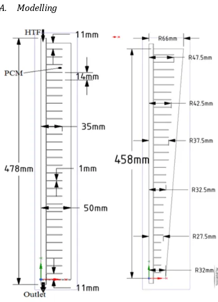
Fig. 1. Thermal energy storage tanks.
In this study, the two cases of thermal energy storage units are analyzed numerically, viz., finned tube in cylindrical tank and finned tube in conical shaped tank as shown in fig.1. These cases are designed for considering same amount of paraffin and same surface area of fins. All designed dimensions are shown in fig.1. Paraffin is filled in between inner and outer pipe and water is flowing through inner pipe. The required properties of paraffin are listed in Table 1. To reduce the computational time, the thermal energy storage units are modeled in a two dimensional domain
.
TABLE I. PROPERIES OF PARAFFIN WAX
Melting Area 58- 61 Heat storage capacity 175±5 KJ/kg Specific heat 2.1 KJ/kg-K Density solid at 35 835 kg/m3
Density liquid at 80 735 kg/m3
Thermal conductivity in both phases 0.2 W/mK
B. Governing Equations
The Equations for the unsteady analysis of the melting process of the PCMs involve NS equation, continuity equation and energy equation. Boussinesq approximation is used for density change.
Continuity:
𝜕𝜌
𝜕𝑡+ ∇. (𝜌𝑉) = 0 (1)
Momentum: 𝜌𝜕𝑉
𝜕𝑡+ 𝜌(𝑉. ∇)𝑉 = − ∇𝑝 + 𝜇∇
2V + ρgβ(T − T
0) + S (2)
Energy: 𝜕
𝜕𝑡(𝜌ℎ) + ∇. (𝜌𝑉ℎ) = ∇. (𝑘∇𝑇) (3)
FLUENT used enthalpy-porosity method for modeling the solidification/melting process. According to this method, expression for enthalpy h is:
ℎ = ℎ𝑟𝑒𝑓+ ∫ 𝐶𝑝𝑑𝑇 + 𝛾𝐿 𝑇
𝑇𝑟𝑒𝑓 (4)
Where, ℎ𝑟𝑒𝑓 is the reference enthalpy at the reference
temperature 𝑇𝑟𝑒𝑓, L is the latent heat and liquid fraction 𝛾 is
defined as
𝛾 = 0 if T <Ts
𝛾 = 1 if T >Tl (5)
𝛾 =T − Ts
Tl − Ts if Ts< T <Tl
Enthalpy porosity method treats distinct phases as porous media with the help of momentum source term S.
S = (1−𝛾)2
(𝛾3+ ϵ) × Amush × V (6)
Where ϵ is a small number (0.001) to prevent division by zero, Amush is the mushy zone constant.
C. Boundary conditions and problem setup
Initial temperature conditions for the HTF and PCM are constant at 270C. Initial velocities of PCM in all direction are
zero. Hot water is flowing from top to bottom with inlet temperature is vary as per Stefan number (0.35, 0.30 and 0.25) and velocity remains same throughout the simulation. Adiabatic wall condition is applied to external surfaces.
Solidification and melting model is used to analyze phase change process. Second order upwind scheme is used for approximating convective flux in the energy equation. SIMPLE algorithm is used for coupling between pressure and velocity. PRESTO is used for pressure correction. The time step is set as 0.1s. The number of iterations per time step is set as 20.
D. Grid independence test and validation.
Three grid sizes, including 160,490, 210,773, and 275,956 cells of quad element, were examined to check the independency of the grid size for the numerical solution. Fine and very fine mesh showed the negligible variation in average temperature of PCM. Also skewness is maintained below 0.67, maximum aspect ratio is 1.96 and minimum orthogonal quality is 0.6755.
305 | P a g e
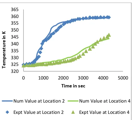
al[8]. The experiment consists in a single thermal energy storage unit with an HTF pipe surrounded by a cylindrical container filled with PCM. The HTF is water and the PCM is paraffin. The simulation has been carried out considering the problem to be two-dimensional and axisymmetric. In Fig 2the comparison of the measured temperature at location 2, location 4 of the Merlin experiment and numerical model with the present results are reported. The present model has a good agreement with the experimental data.
Fig. 2. Comparison of the measured temperature at location 2, location 4 of the Merlin experiment and numerical model.
III. RESULTS AND DISCUSSION
In this analysis, thermal performances of latent heat storage system with two different shapes of storage tank are compared. These cases are compared by varying the Stefan number where Stefan number is the ratio of specific heat to the latent heat.
(a) At time 1000sec
(b) At time 2000sec
(c) At time 3500sec
(d) At time 6000 sec
Fig. 3. Contour of liquid fraction for Stefan number 0.35
320 325 330 335 340 345 350 355 360 365
0 1000 2000 3000 4000 5000
Te
m
p
era
tu
re
in
K
Time in sec
306 | P a g e
1. Fig. 3 shows the contours of a liquid fraction with respect to time for the case 1nd and 2rd. At the
starting stage, heat is carried out by only conduction in the solid state and heat flows in outward direction according to the temperature distributions. Initially liquidification take place around the fins and pipe wall because of heat transfer is setup between PCM and HTF.
2. Amount of liquid PCM slowly increases with time until the storage tank is completely filled with the liquid PCM. The liquid fraction is increasing faster in up to 2000 sec to 2300 sec after that it required more time as seen in fig. 4. This is due to paraffin around fins melt fast and away from fins required more time because of the temperature gradient. 3. Effect of Stefan number on the melting behavior of
paraffin has been investigated for both the cases as shown in fig. 4 (a) and (b). When the Stefan number increase from 0.25 to 0.35 reduces the time required to melt paraffin which results in better performance of the system. This is due to increases temperature between the water and the paraffin
4. During the charging process (melting process), it is seen that temperature in the upper part of thermal energy storage tank is higher than that of the bottom side. Therefore, paraffin melts faster in upper part rather than bottom side as shown in fig. 3. This effect is due to change in paraffin density, the hot PCM (melted PCM) moves upward by a natural process which results in the increase in temperature in the upper side of a tank.
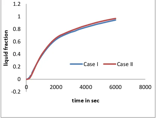
5. Due to above reason, in conically shaped storage tank melting occurs 2.56% faster due to more amount of paraffin in the top side as compare to the bottom side. Liquid fraction for both the cases are same up to 2000 seconds then the time required for conically shaped storage tank is less as compared to cylindrically shape as shown in fig 5.
Fig. 4(a). Effect Stefan number on melting process for case I
Fig. 4(b). Effect Stefan number on melting process for case II
Fig. 5. Comparison of liquid fraction between case I and case II
.
IV. CONCLUSIONS
In the present study, a numerical analysis of melting process in thermal energy storage system has been performed. The CFD analysis used enthalpy porosity method yielding quantitative data about the heat transfer rates and melt fraction.
1. In staring stage of melting process are dominated by conduction heat transfer later on melting is affected by natural convection.
2. Paraffin at the topside of the unit attains the melting temperature in a less time than paraffin at the bottom side.
3. Inlet condition of hot water strongly affected the melting rate: larger Stefan number, that is higher inlet temperature, can induce a reduction in
-0.2 0 0.2 0.4 0.6 0.8 1
0 2000 4000 6000 8000
Li
q
u
id
fra
ct
io
n
Time in sec
Ste 0.35 Ste 0.30 Ste 0.25
-0.2 0 0.2 0.4 0.6 0.8 1 1.2
0 2000 4000 6000 8000
Li
q
u
id
f
ra
ct
io
n
Time in Sec
Ste 0.35 Ste 0.30 Ste 0.25
-0.2 0 0.2 0.4 0.6 0.8 1 1.2
0 2000 4000 6000 8000
liq
u
id
fra
ct
io
n
time in sec
307 | P a g e
melting time up to 11% with respect to original condition.
4. The Time required for melting process for cylindrically shaped storage tank is 2.56% more than time requires for conically shaped storage tank.
REFERENCES
[1] F. Fornarelli, S.M. Camporeale, B. Fortunato, M. Torresi, P. Oresta, L. Magliocchetti, A. Miliozzi and G. Santo, “CFD analysis of melting process in a shell-and-tube latent heat storage for concentrated solar power plants”, Applied Energy, vol. 164, pp.711– 722, 2015.
[2] E. Guelpa, A. Sciacovelli and V. Verda, “Entropy generation analysis for the design improvement of a latent heat storage system”, Energy, vol. 53, pp. 128– 138, 2013
[3] A. Dinkar, M. Agarwal and G.D. Agarwal, “Experimental assessment on thermal storage performance of beeswax”, Applied thermal Engineering, vol. 111, pp. 358-368, 2016.
[4] N.H.S Tay, M. Belusko and F. Bruno, “Designing a PCM storage system using the effectiveness-number of transfer units method in low energy cooling of buildings’, Energy and Buildings, vol. 50, pp. 234– 242.
[5] Z.N. Meng and P. Zhang, “Experimental and numerical investigation of a tube in tank latent thermal energy storage unit using composite PCM”, Applied Energy, vol. 190, pp. 524-539, 2017.
[6] A. Sciacovelli, V. Verda and F. Colella, “Numerical model for storage systems based on phase-change materials”, International Mechanical Engineering Congress and Exposition, pp. 1-9, 2011.
[7] A. El-Sawi, F. Haghighat, and H. Akbari, “Assessing long-term performance of centralized thermal energy storage system”, Applied Thermal Engineering, vol. 62, pp. 313–321, 2013.
[8] K. Merlin, D. Delaunay, J. Soto and L. Traonvouez, “Heat transfer enhancement in latent heat thermal storage systems: Comparative study of different solutions and thermal contact investigation between the exchanger and the PCM”, Applied Energy, vol. 166, pp.107–116, 2016.
[9] W. Humphries and E. Griggs, “A design handbook for phase change thermal control and energy storage devices”, NASA TP-1074, 1977.