Study and Analysis of A Controlled Differential
Continuously Variable Drive
Devesh R Kulkarni Vijay Firake
PG Scholar Assistant Professor
Department of Mechanical Engineering Department of Mechanical Engineering J.T.Mahajan College of Engineering Faizpur, Maharashtra,
India
J.T.Mahajan College of Engineering Faizpur, Maharashtra, India
Abstract
Now a day’s development trends in car industry and mobile machines are driven by universal concerns on energy limitations and greenhouse gases reduction, more energy efficient and environmentally friendly vehicles will be needed. As the increasing concerns in the impact of vehicle emissions of carbon dioxides and Nitrogen oxides on the biosphere combined with today’s shortage fuel, hence need to find alternate fuel solutions or develop the transmission system in such a way that lower consumption and lower emission should takes place. Continuously variable drive is the type of automatic transmission that allows selection of infinite number of transmission ratios within the finite range i.e. between minimum and maximum value. Continuously variable drive is 34.91% more efficient than that of manual transmission. In order to achieve emission reduction and fuel economy needs to improve fuel efficiency. Continuously variable drive can be improved by coupling differential gear assembly to one of variable speed drives; we can increase the speed variation range at the expense of the horse power range. Numerous combinations of the variables are possible.
Keywords: Differential gear assembly, continuously variable drive, Power, Torque, Ratio Control, Torque Control, CVD input pulley Dia.-D1 and CVD output pulley Dia.-D2
_______________________________________________________________________________________________________
I. INTRODUCTION
CVT allow the engine to operate always in its optimum R.P.M., whatever the vehicle’s speed.Which leads to improve the fuel economy. Continuously variable transmission is 35% more efficient than that of manual transmission. The existing inventions are based on friction type, hydrostatic type, ratcheting type which is all mechanical systems with inherent limitations, (compared to traditional transmissions). Though CVTs are not new technology, limited torque capabilities, poor reliability and the poor control schemes have inhibited their growth. Controlled differential continuously variable drive can improve CVTs capacity, efficiency & durability. Performance of continuously variable drive can be improved by coupling differential gear assembly to one of variable speed drives.we can increase the horsepower capacity at the expense of the speed range or we can increase the speed range at the expense of the horse power range. The acting forces within the drive can be precisely calculated, assuring a sound drive design which is especially important for heavy-duty applications. Another important feature of this drive is its compactness, low weight and obviously its low cost.
II. RELATED WORK
Friction type CVT in automotive powertrain emphasizing on the two concept of ratio and torque control have been proposed in (R.Fuchs at 2010). Now a day’s development trends in car industry and mobile machines are driven by universal concerns on energy limitations and greenhouse gases reduction, more energy efficient and environmentally friendly vehicles will be needed. As the increasing concerns in the impact of vehicle emissions of carbon dioxides and Nitrogen oxides on the biosphere combined with today’s shortage fuel, hence need to find alternate fuel solutions or develop the transmission system in such a way that lower consumption and lower emission should takes place.have been propose in (IJIERT by mane dhirajkumar in 2015). Continuously Variable Transmission (CVT) offers a continuum of gear ratios between desired limits. This allows the engine to operate more time in the optimum range have been proposed in (IJERA by Vishnu Salen in March 2015)
III. PROPOSED METHOD
Problem Definition:
performance. So it is decided to design, development, testing of controlled differential continuously variable drive unit to improve the Speed variation range as well as performance of continuously variable drive unit
Features of Controlled Differential Continuously Variable Drive:
1) Improved speed variation range can be obtained by Controlled differential continuously variable drive. 2) The developed system offers high horse Power Capacity & hence efficiency.
3) High torque transmission capacity with simpler & effortless operation. 4) Greater drive accuracy offers eco-friendly drive.
Loading Condition:
While taking analysis on modified differential controlled continuously variable transmission system. I firstly design a modified system with modified diameter of different part such as input and out pulley then find stress analytically and compare this stress to theoretically system. When these stress beyond design stress I conclude that my design is safe.
IV. METHODOLOGY
While design a modified system I choose following method.
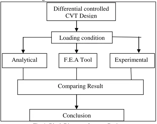
Fig. 1: Block Diagram of system Design
In this experiment firstly I study failure of the different part of the system then I select best material for different part of the system. After that In this work I design modified system with new dimension and compare result analytically, F.E.A tool ANSYS workbench 14.5 and experimentally by using tachometer.
Technical specification:
In this work I modify a dimension of different part of the system such as diameter of input and output pulley, diameter of planet pin and diameter of shaft.and find stress in ANSYS workbench 14.5.
Table – 1
Technical Specification of system
Specification Denoted by Standard system Modified system
Modulus of rigidity G 80x103 N/mm2 80x103 N/mm2
Modulus of Elasticity E 210x103 N/mm2 210x103 N/mm2
Inside diameter of pulley d 60 Mm 60 Mm
outside Diameter of pulley D 120 Mm 100 Mm
Ultimate tensile strength fult 800 N/Mm2 800 N/Mm2
Yield strength fyield 680 N/Mm2 680 N/Mm2
Calculation of maximum shear stress of system.
Power=2×3.14×N×T
60
Torque=𝜋
16× 𝜎 × 𝑑
3
Differential controlled CVT Design Loading condition F.E.A Tool
Analytical Experimental
Comparing Result
V. INTRODUCTION TO SOFTWARE
CREO/Engineer:
Creo-ENGINEER is a feature based, solid modelling program. It's application is significantly different from conventional drafting programs. In conventional drafting, various views of a part are created to describe the geometry. The design procedure is to create a model, view it, and generate any drawings which are required.
Capabilities of the Software:
The Creo/Engineer is a software application within the CAD/CAM/CAE category. It is a feature-based modelling architecture incorporated into a single database philosophy with advanced rule-based design capabilities. The capabilities of the product can be divided into the three main heading as Engineering Design, Analysis and Manufacturing.
ANSYS Workbench:
ANSYS software has a capability to solve any type of mechanical problem in the form of geometry. Various types of analysis is conducted in workbench. In this work I used static structural analysis for getting the results.
a) Input pulley=60 Mm Dia b) Mesh model
d) Result showing stress are within limit than design Stress Fig. 2: (a,b,c,d)-input pulley analysis
c) Loading condition of applying 19 N-m
d) Result showing stress is within limit than design stress Fig. 3: (a, b, c, d) output pulley analysis
Experimentally:
Testing of drive has carried out by using following procedure: 1) Start motor by turning electronic speed aviator’s knob.
2) Now the mechanism should run & stabilize at certain speed (say 2750rpm)
6) Place the pulley cord on continuously variable drive output pulley and add 02 Kg weight into the pan, note down the output speed for this load by means of tachometer.
7) Added another 02 Kg load into the pan & took the reading. 8) In this way 12 readings have taken for 24 Kg.
9) Now the readings should be tabulate in the observation table.
10) For second observation table Select Second profile Gear ratio 3:5 at Continuously Variable Drive. (i.e. Input Pulley Dia. = 100 mm and Output Pulley Dia. = 60 mm) and repeated the procedure.
11) For third observation table Select Third profile Gear ratio 3:4 at Continuously Variable Drive. (i.e. Input Pulley Dia. = 83 mm and Output Pulley Dia. = 60 mm) and repeated the procedure.
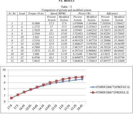
12) In this way we can select infinite gear ratios within finite range and repeat the procedure for precise change in speed ratio. 13) Finally Plotted Following performance characteristics Curves
1) Torque Vs speed characteristic. 2) Power Vs speed characteristic 3) Efficiency Vs speed characteristic
VI. RESULT
Table – 2
Comparison of present and modified system
Sr. No Load Torque (N-m) Speed (RPM) Power (W) Efficiency
Present System Modified System Present System Modified System Present System Modified System
1 2 0.5886 17.5 17.9 1.078806 1.103464 7.192038 7.356427
2 4 1.1772 17 17.5 2.095965 2.157611 13.9731 14.38408
3 6 1.7658 16 16.45 2.95901 3.042232 19.72673 20.28155
4 8 2.3544 15.1 15.65 3.723421 3.859042 24.82281 25.72695
5 10 2.943 14.3 14.85 4.407692 4.577218 29.38461 30.51479
6 12 3.5316 13.5 14.35 4.993329 5.307724 33.28886 35.38483
7 14 4.1202 12.9 13.85 5.566637 5.976584 37.11092 39.84389
8 16 4.7088 12.1 13.15 5.967337 6.485163 39.78224 43.23442
9 18 5.2974 11.35 12.6 6.297143 6.990661 41.98095 46.60441
10 20 5.886 10.6 11.95 6.53448 7.366702 43.5632 49.11135
11 22 6.4746 10.1 11.25 6.848875 7.628697 45.65917 50.85798
12 24 7.0632 9.55 10.45 7.064636 7.730413 47.09757 51.53609
Fig. 4: comparison of power of present and modified system
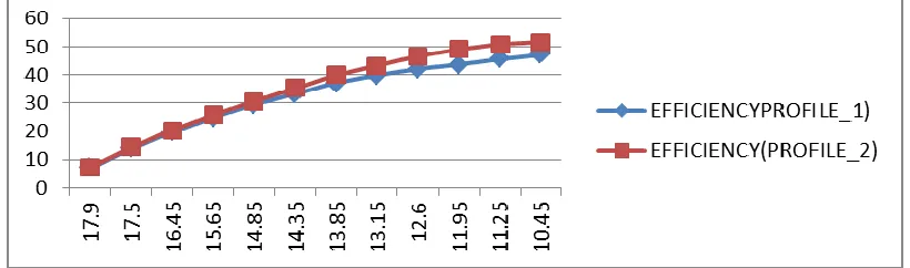
Fig. 5: Comparison of efficiency of present and modified system
Characteristics curve Efficiency Vs Speed have drawn for Profile 01 (D1=120 AND D2=60); Profile 02 (D1=100 AND D2=60) speed increase for the same Efficiency. For each profile, as Efficiency increases, speed decreases slowly up to 51.53609 Efficiency. Above 51.53609 Efficiency, speed decreases at faster rate and again speed is constant
VII.CONCLUSION
From the experimental setup of Controlled Differential Continuously Variable drive, the following results were obtained
1) This paper describes the controlled differential continuously variable drive mainly emphasizing on improvement of performance of drive in the sense of two concepts mainly speed variation range and efficiency.
2) Speed variation range for the controlled differential continuously variable drive improved considerably approximately 46 % to 50 %
3) As profile changes (Gear ratio increases 1:2-3:5-3:4) speed increase for the same Efficiency. 4) Torque transmitted by the drive drops with increase in speed marginally.
5) Continuum ratio control and torque control concept achieved so that developed system does not act as actuator applying load to the engine.
6) The developed system enables for eco- friendly drive by minimizing emission of Cox and Nox gasses.
REFERENCES
Reference Books:
[1] V.B. Bhandari, Design of machine elements, 3rd edition, Tata McGraw hill publication, 2010, India [2] Joseph E. Shingley, Theory of machines and mechanisms, 3rd edition, Oxford publication, 2009
Reference Papers:
[1] “Tonmoy Dutta Roy”,“Effect of continuously variable unit on powertrain dynamics”. A parametric free vibration analysis, proceedings of the institution of mechanical Engineers, Part D: Journal of Automobile Engineering. Vol: 218, 2004, pp. 471- 484. Faculty of Engineering, University of Technology, Sydney.
[2] “R.Fuchs, Y.Hasuda, Y.Rothernbuehler and K. Matsumoto”,“Control concepts of continuously variable transmissions (CVT)”. JTEKT Engineering Journal English Edition No.10012006, pp. 24-29.
[3] “Norman H. Beachley and Andrew A. Frank”, “Continuously variabletransmissions: Theory and Practice.”College of Engineering Universityof Wisconsin, Madison This work was supported by the United StatesNuclear Regulatory Commission under a Memorandum of Understandingwith the United States Department of Energy. 12th Intersociety EnergyConversion Engineering Conference, Sept. 1977, pp. 26-33.
[4] “Chengyan, Sun”,“Hydrostatic-mechanical power split CVT” Tampere university of technology, Master’s Degree program in Machines Automation. Master of Science thesis, Jan-2011.Agratechnische Forschung Vol.3, 1997, No.1:19-27.
[5] “Druten, Ro¨ellM.Van”,“Transmission design of the Zero Inertia Powertrain” by Ro¨ellM. vanDruten. -Eindhoven: Technische University Eindhoven, Proefschrift. - ISBN 90-386- 2603-7 NUGI 834, 2001, pp. 01-131.