Themed Section : Engineering and Technology DOI : https://doi.org/10.32628/IJSRSET1841116
Design and Simulation of IMC based PI Controller for a MIMO
Process
C. Ravikumar1 Dr. D. Sivakumar2
1Department of Instrumentation and Control Engineering, A.V.C. College of Engineering, Mannampandal,
India
2 Department of Electronics & Instrumentation Engineering, Annamalai University, Chidambaram, India
ABSTRACT
The objective of this paper is to develop the Internal Model Control (IMC) based PI Controller for a MIMO (SISO) Process. The controller thus developed is implemented on Laboratory interacting coupled tank process through simulation. This can be regarded as the relevant process control in petrol and chemical industries. These industries involve controlling the liquid level and the flow rate in the presence of nonlinearity and disturbance which justifies the use of IMC based PI Controller scheme. For this purpose, mathematical models are obtained for each of the input-output combinations using white box approach and the respective controllers are developed. A detailed analysis on the performance of the chosen process with these controllers is carried out. Simulation studies reveal the effectiveness of proposed controller for MIMO process that exhibits nonlinear behaviour.
Keywords : Interacting coupled tank system, IMC, PI controller, MIMO.
I. INTRODUCTION
The controls of liquid level in multiple tanks and flow between the tanks are basic problems in the process industries. The process industries require liquid to be pumped and stored in the tanks and then pump it to another tank. Often the tanks are so coupled together that the levels interact and these must also be controlled.
Classical Proportional Integral (PI) controller remains the most popular approach for industrial process control. According to a survey conducted by Japan electric Measuring Instruments Manufacturers Association in 1989, 90 percent of the control loops in industries are of PID type [1] and only small portion of the control loop works well. Also survey by ender [10-11] indicates 30 percent of the controller are
operated in manual mode and 20 percent of the loops use factory tuning. It means that PID controller is widely used but poorly tuned. Poor tuning can lead to mechanical wear associated with excessive control activity, poor control performance and even poor quality products. However, tuning of PID controller parameters is a challenging task.
Hence, these parameters may not provide satisfactory performance under transient conditions. Neural network based methods are especially useful for classification and function approximation problems which are tolerant of some imprecision having lots of training data available. Consequently, these tuning methods are less robust under momentary disturbances.
An alternative to this controller is the usage of Internal Model controller (IMC) which gives satisfactory performance for Interacting coupled tank system Level systems [1]. In this paper an Internal Model Controller is designed and implemented to Interacting coupled tank system [2]. This controller uses the model of the process to run in parallel with the actual process [3]. The IMC design procedure is exactly same as the open loop control design procedure. Unlike the open loop control the IMC structure compensates for disturbances and model uncertainty.
The paper is organized as follows: The laboratory interacting coupled tank process setup chosen for the study is detailed first. The procedure involved in developing Internal Model Control (IMC) based PI Controller is presented. In the third section simulation results on interacting coupled tank will be given with comparison study of closed loop PID controller response using Ziegler-Nichols and IMC tuning methods. The final section concludes our approach of IMC based PID controller for MIMO process.
II. PROCESS DESCRIPTION
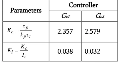
The schematic diagram of the chosen Interacting coupled tank system is illustrated in Fig. 1.
The mass balance equations of tank1 and tank2 are given in Equations 1 and 2. The rate of change of liquid volume in each tank is equal to the net flow of
liquid into the tank. The volumetric inflow rate into the tank1 and tank2 are qin1 and qin2. The volumetric
flow rate from the tank1 and tank2 are q01 and q02.
Flow rate between tank1 and tank2 is q12. The height
of the liquid level is h1 in tank1 and h2 in tank2.
12 1 1 1
1 q q q
dt dh
A in o
(1)
12 2 2 2
2 q q q
dt dh
A in o (2)
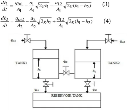
The system model can be formulated by ordinary differential equation using Bernoulli’s law as shown in Equations 3 and 4.
) ( 2
2 1 2
1 12 1 1 1
1 1
1 gh h
A a gh A a A q dt
dh in (3)
) ( 2
2 1 2
1 12 2 2 2 2
2
2 g h h
A a gh A a A q dt
dh in
(4)
Figure 1. Schematic diagram of coupled tank process
The cross sectional area of tank1 and tank2 are A1=A2=1130.4cm2, restriction areas in the outlet pipes
of tank1 and tank2 are a1=a2= 3.9cm2. Restriction area
of interconnecting pipe is a12=1.27cm2 and g is the
specific gravity. The maximum capacity of two tanks is 25cm. Equations 3 and 4 describe the coupled tank system dynamics. To design the control systems for this process the equations are linearized by considering small variations in qin1, qin2, h1 and h2 [3].
The variations are measured with respect to nominal operating conditions. The hand valves are adjusted so that the levels in both the tanks are brought to nominal condition initially. Nominal values of qin1,
qin2 are 26 and 20.75 l/hr and for h1 and h2 are 12.5 and
Rearranging the equations (3) & (4) and then taking laplace transform on both sides, we get
( ) ( )
1)
( 1 12
1 1
1 q s q s
s R s
h in
( ) ( )
1 )( 2 12
2 2
2 q s q s
s R s
h in
1. Multiloop Process
The four models relating the two controlled outputs h1 and h2 with two manipulated inputs qin1 and qin2 are
essential to design the multiloop controllers [5]. The model transfer functions with the flow rates as manipulated inputs and the levels as controlled outputs can be written as follows:
1 2 2 ) ( 22 ; 1 2 1 ) ( 12 ; 2 1 2 ) ( 21 ; 2 1 1 ) ( 11 in q in q h s G in q in q h s G in q in q h s G in q in q h s G
The Transfer functions are computed and represented in matrix form as follows:
s . s . s . s . G G G G G 1 81 633 0 1 106 443 0 1 111 583 0 1 61 737 0 22 21 12 11
The block diagram of Multiloop control system of a coupled tank process employed with Gc1 and Gc2 as PI
controllers for tank1 and tank2 is shown in Fig. 2.
Figure 2. Multiloop PI control system
Synthesis Method of Tuning
The PI controller parameters are tuned using synthesis method for the two first order processes G11
and G22 obtained from modelling. Kc is proportional
gain. Ti is integral time. Ki is integral gain.
c is closedloop time constant of the process. Controller parameters are determined and tabulated in Table I.
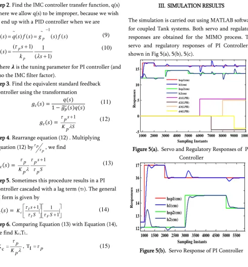
Table I. Controller Parameters for PI Controller
Parameters Controller
Gc1 Gc2
τ k τ K c p p
c 2.357 2.579
T K K i c
i 0.038 0.032
2. IMC based PI Controller
A more comprehensive model based design method; Internal Model Control was developed by Morari and co-workers. The IMC method is based on the simplified block diagram as shown in Fig. 3.
) ( ~
s r
Figure 3. Internal Model Control (IMC)
We have found that the IMC structure can be rearranged to the feedback control (FBC) structure, as shown in Figure 4. This reformulation is advantageous because we will find that a PID controller often results when the IMC design procedure is used. Also, the standard IMC block diagram cannot be used for unstable systems, so this feedback form must be used for those Cases.
Figure 4. Standard Feedback Diagram Illustrating the
Equivalence with Internal Model Control.
Step 1.Find the PI-equivalent to IMC for a First-order process,
d(s)
r(s)
+
+
+
y(s) u(s)-
+
q(s)g
p(s)
-
y(s)+
+
-
+
r(s)
u(s
d(s)
)
g
c(s)
g
p(s)
(5)
(6)
=
)
1
(
)
(
~
s
k
s
g
p p p
Step 2. Find the IMC controller transfer function, q(s) - here we allow q(s) to be improper, because we wish to end up with a PID controller when we are
)
1
(
1
)
1
(
)
(
)
(
)
(
)
(
)
(
)
(
1 ~ ~
s
k
s
s
q
s
f
s
g
s
f
s
q
s
q
p p p
where 𝝀 is the tuning parameter for PI controller (and also the IMC filter factor).
Step 3. Find the equivalent standard feedback controller using the transformation
( ) ( ) ̃( ) ( ) ( ) S p K s p 1
Step 4. Rearrange equation (12) . Multiplying equation (12) by
p p
, we find
( ) S p s p p K p
1
Step 5. Sometimes this procedure results in a PI controller cascaded with a lag term (τF). The general
PI form is given by
( ) 1 1 1 S S s K F I I
c
Step 6. Comparing Equation (13) with Equation (14), we find Kc,TI,.
p K p = c
K , TI =p
Step 7. For MIMO Process, we will consider two models from equation (7),
) 1 61 ( 737 . 0 ) ( 11 ~ s s gp 1 106 443 0 ) ( ~
21
s . s gp
Step 8. We find Kp,τp values by comparing equation
(16) with equation (8) and then substituting these values in equation 15) we get two set of controller parameters are shown in Table II.
Table II. Controller parameters for IMCPI
III. SIMULATION RESULTS
The simulation is carried out using MATLAB software for coupled Tank systems. Both servo and regulatory responses are obtained for the MIMO process. The servo and regulatory responses of PI Controller is shown in Fig 5(a), 5(b), 5(c).
Figure 5(a). Servo and Regulatory Responses of PI Controller
Figure 5(b). Servo Response of PI Controller
1000 2000 3000 4000 5000 6000 7000 8000 9000 10000 -5 0 5 10 15 Sampling Instants R e sp on se s hsp1(cm) h1(cm) hsp2(cm) h2(cm) d1(LPH) d2(LPH) d3(LPH) d4(LPH)
1000 1500 2000 2500 3000 3500 4000 4500 5000 5500 12 13 14 15 16 17 Sampling Instants R e s p on s e s hsp1(cm) h1(cm) hsp2(cm) h2(cm) Parameters Controller
Gc1 Gc2
p K p = c
K 82.76 239.27
p = I
T 61 106
Figure 5(c) Regulatory Response of PI Controller
The servo and regulatory responses of IMC based PI Controller is shown in Fig 6(a), 6(b), 6(c).
Figure 6(a) Servo Response and Regulatoryof IMC PI controller
Figure 6(b) Servo Response of IMC PI Controller
Figure 6(c) Regulatory Response of IMC PI Controller
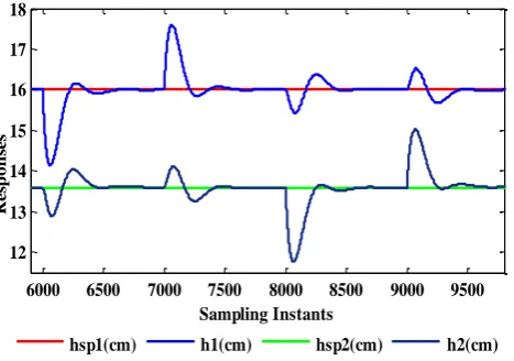
The regulatory responses of IMCPI controller is shown in figure 7. The figure 7(a), 7(b) shows the interaction of h2 when positive and negative disturbance is applied in h1.
Figure 7(a) Regulatory Response of h2 for IMC PI Controller
Figure 7(b) Regulatory Response of tank2 for IMC PI Controller
6000 6500 7000 7500 8000 8500 9000 9500
12 13 14 15 16 17 18
Sampling Instants
R
e
sp
on
se
s
hsp1(cm) h1(cm) hsp2(cm) h2(cm)
1000 2000 3000 4000 5000 6000 7000 8000 9000 10000
-5 0 5 10 15 20
Sampling Instants
R
e
s
p
o
n
s
e
s
hsp1(cm) h1(cm) hsp2(cm) h2(cm) d1(LPH) d2(LPH) d3(LPH) d4(LPH)
1000 1500 2000 2500 3000 3500 4000 4500 5000 5500 12
13 14 15 16 17
Sampling Instants
R
e
s
p
o
n
s
e
s
hsp1(cm) h1(cm) hsp2(cm) h2(cm)
6000 6500 7000 7500 8000 8500 9000 9500 13
14 15 16 17
Sampling Instants
R
e
s
p
o
n
s
e
s hsp1(cm)
h1(cm) hsp2(cm) h2(cm)
6000 6010 6020 6030 6040 6050
13.595 13.6 13.605
Sampling Instants
R
e
sp
on
se
s
hsp1(cm) h1(cm) hsp2(cm) h2(cm)
7000 7010 7020 7030 7040 7050
13.597 13.598 13.599 13.6 13.601 13.602
Sampling Instants
R
e
s
p
o
n
s
e
s
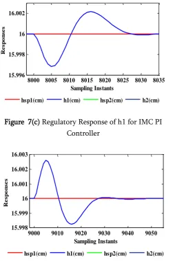
The figure 7(c), 7(d) shows the interaction of h1 when positive and negative disturbance is applied in h2.
Figure 7(c) Regulatory Response of h1 for IMC PI Controller
Figure 7(d) Regulatory Response of h1 for IMC PI Controller
Performance Measures of PI and IMCPI controller for h1 and h2 in shown in Table III and Table IV respectively.
Table III. Performance Measures of PI and IMCPI for h1
Table IV. Performance Measures of PI and IMCPI for h2
IV. CONCLUSION
The performance of coupled tank MIMO process has been investigated using IMC based PI controller design. Interaction effects are projected for both servo tracking and load disturbance rejection. From the plots, it is clear that the overall system performance with IMCPI is observed to have better tracking and disturbance rejection than that of the system with PI controller. From the Table it is observed that IMCPI have better settling time and ISE values when compared to PI controller. The resulting performance could be improved by a better choice of the gain. This concludes that the Internal Model Control based PI controller is applicable for nonlinear coupled tank systems.
V. REFERENCES
[1]. Arjun Numsomran, Tianchai Suksri and Maitree Thumma, “Design of 2-DOF PI Controller with Decoupling for Coupled-Tank Process,” in Proc. International Conference on Control, Automation and Systems, Korea, pp.339-344, October 17-20, 2007.
[2]. Chatchaval pornpatkul and Tianchai suksri, “Decentralized Fuzzy Logic Controller for TITO Coupled Tank Process”, in Proc. ICROS-SICE International Joint Conference, Japan, pp.2862-2866, August 18-21, 2009
[3]. Morari, M. and E. Zafiriou Robust Process Control, Prentice-Hall, Englewood Cliffs, NJ (1989).
[4]. S.Vadivazhagi,Dr.N.Jaya, Modelling and Simulation of Interacting Conical Tank Systems, International Journal of Innovative Research in
8000 8005 8010 8015 8020 8025 8030 8035 15.996
15.998 16 16.002
Sampling Instants
R
e
sp
o
n
se
s
hsp1(cm) h1(cm) hsp2(cm) h2(cm)
9000 9010 9020 9030 9040 9050 15.998
15.999 16 16.001 16.002 16.003
Sampling Instants
R
e
sp
o
n
se
s
Science,Engineering and Technology,Vol.3,Issue 6,2014.
[5]. Rivera, D.E., M. Morari and S. Skogestad “Internal Model Control. 4. PID Controller Design,” Ind. Eng. Chem. Proc. Des. Dev., 25, 252-265 (1986).
[6]. Rotstein, G.E. and D.R. Lewin “Simple PI and PID Tuning for Open-Loop Unstable Systems,”Ind. Eng. Chem. Res., 30, 1864-1869 (1991).
[7]. Rathikarani Duraisamy and Sivakumar Dakshinamuthy, “An adaptive optimization scheme for controlling air flow process with satisfactory transient performance”, Maejo International Journal of Science and Technology, vol.4, no.2, pp.221-234, 2010. [8]. George Stephanopoulos, Chemical Process
Control – An introduction to Theory and Practice, PHI Private limited, New Delhi, 2005. [9]. Daniel E. Rivera, Manfred Morari, and Sigurd Skogestad, Internal Model Control. 4. PID Controller Design, Ind. Eng. Chem. Process Des. Dev,Vol 25, pp.252-265,1986.
[10]. S.Nithya, N.Sivakumaran, T.Balasubramanian and N.Anantharaman, Model based controller design for a Spherical Tank Process in real time ,Proceedings of International journal of Simulation,System,Science and Technology, Vol.9, No.A4, pp.247-252,2008.
[11]. P. Manikandan, M. Geeta, “Real time Implementation and Performance Analysis of an Intelligent Fuzzy Logic Controller for Level Process”, Proc. of Int. Conf. on Computing,
Communications and Networking