© 2016 IJSRSET | Volume 2 | Issue 4 | Print ISSN : 2395-1990 | Online ISSN : 2394-4099 Themed Section: Engineering and Technology
Fabrication of Multiple 3D Ring Resonators by FDTD Method
Murali Krishna Bathula
Electronics and Communication Engineering, UCEK, JNTU Kakinada, Andhra Pradesh, India
ABSTRACT
This paper presents multiple split ring resonators (MSRR) by suppressing the electric dipole moment approach. To tremendously reduce the loss, the loss mechanism of the MSRR is theoretically analyzed in detail. The non-uniform current distribution on the SRR loop results in the residual electric dipole moment and thus brings the high radiation losses. Three different SRR configurations that the lumped capacitor, the distributed capacitor and the dielectric medium are incorporated into the SRR Meta material are conceived, by which the uniform current distribution can be observed. We demonstrate a self-assembly strategy for fabricating three dimensional (3D) meta materials. A high-spatial-order scheme of the finite-difference time-domain (FDTD) method has been applied to the three-dimensional (3D) full wave analysis of optical dielectric rib-waveguide circuits such as ring resonator filters. The Eigen-modes of the SRRs can be excited by normal illumination with polarization state parallel to the erected SRRs Keywords: MSRR(Multiple Split Ring Resonator), FDTD (Finite Difference Time Domain ), Polarization, Dipole, Spatial order.
I.
INTRODUCTION
The meta materials are the artificial structures which exhibiting unconventional engineered responses, such as artificial magnetism [1–3], negative index refraction of [4–5], sub wavelength imaging, field enhancement, and toroidal response [4-6]. Recently tailored Meta materials reveal their specific optical properties which are primarily depends on the dimensions and configurations. Negative index meta materials (NIMs) have attracted great attention due to their fascinating electromagnetic (EM) properties such as perfect lens, near-field imagings, cloakings, reversal of the Doppler However, the negative permittivity and permeability produced by electromagnetic resonance can bring about a very high loss Reducing the losses is critical for many applications expected from the NIM technology, including perfect lenses, electromagnetic cloaks, and so on.
Therefore, a number of diverse strategies have been proposed toward overcoming the issue of high losses in meta materials. Achieving such reduction of losses by geometric tailoring of the meta material designs appears to be out of reach. So far, the electromagnetically induced transparency (EIT) effects have been introduced
II.
METHODS AND MATERIAL
A. Fabrication Procedures
A standard EBL (Raith 50, Raith GmbH) process is employed for pattering the 2 D templates. Note that, the connection pad plays a role as a connection point between 3D SRRs and substrate, which is used to prevent the SRRs to be free standing structure after dry etching, To avoid charging problem during e-beam exposure process, After e-e-beam exposure the sample is rinsed with de-ionized water to remove Espacer, and then developed in a solution of methyl isobutyl ketone (MIBK) and isopropyl alcohol (IPA) of MIBK:IPA = 1:3.
Figure 1. The schematic diagram with the feature sizes of 3D SRRs before (a) and after (b) released from the substrate by dry etching method. The parameters of our designed SRRs, (c) The fabricated sample is illuminated by an x-polarized light at normal incidence.
B. Realization of The Ultra-Low Loss SRR
To suppress the residual electric dipole moment in the unit cell of the SRR, the circular current on the SRR is expected to exhibit the uniform distribution. We demonstrate that such a dramatically decreased the Meta material loss is achieved by incorporating the lumped and distributed capacitors and the dielectric medium into the existing SRR. Such three arrangements that, as is shown in the following, induce the redistribution of the surface current of the SRR loop and thus suppress the residual electric dipole moment associated with the existing SRR. For simplifying the description of SRRs in the paper, we use throughout the manuscript the abbreviations “SRR LC” for the SRR with lumped capacitor. “SRR-IDCs” for the SRR with inter digital capacitors and the abbreviations “SRR-die” for the SRR with dielectric medium.
Figure 2. (a) The retrieved results for the real and imaginary parts.
(b) The absorption losses of the SRR and SRR-LC. (c) The FOMs of the SRR and SRR-LC. (d) The surface current distribution at the frequency of the magnetic resonance (1.74 GHz) for the SRR-LC, the maximal scaling is used.
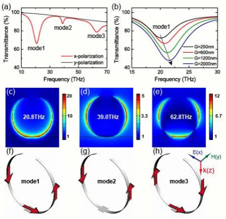
y many experimental methods (for example electron beam excitation or adjusting the environment temperatures), the electromagnetic response of the SRRs can b e controlled correspondingly. To demonstrate these reconfigurable properties, we simulated SRRs arrays with different gap width. Obviously “mode 1” shifts towards high frequency region while the gap width is increased. It can be qualitatively understood in the picture of equivalent LC circuit model The total length of SRR kept same means that the effective inductance almost does not change. But the capacitances of the equivalent circuit will definitely decrease while the gap width becomes larger. Considering that the resonance frequency is proportional , the blue-shift of the resonance mo des with increasing gap width is a natural.
The tailored 3 D SRRs can be constructed through precise arrangement of film parameters of 2D templates. The radii of curvature of erected arms are decreased with decreasing arm width or film thickness under the same arm length. In addition, we have also observed the tunable characteristic depending on the temperature changes of our SRRs. By means of this strategy, we actually fabricate a new kind of 3D, upright, and tunable meta materials Transmittance spectra and magnetic field patterns of the fabricated 3D SRRs are calculated by FEM simulation which demonstrates that both electric and magnetic resonance modes can be excited with x-polarized normal incident wave. A blue-shift of the resonance modes with increasing gap width is investigated in the case of reconfigurable application. As a consequence, the radiation loss of the SRR is greatly reduced and the low loss SRR is achieved.
C. SRR-IDCs
As discussed above, the lumped capacitor can be incorporated into the SRR structure to suppress the residual electric dipole moment and thus achieve the low loss magnetic meta material. However lumped elements are not available at higher radio frequencies such as millimeter waves because of their distributed parameters. As for the next generation of phoXonic, plasmonic, opto-mechanical and micro fluidic devices, the capability to create 3D microstructures is highly desirable. Fabrication of such structures by conventional top-down techniques generally requires multiple time-consuming steps and is limited in the ability to define features spanning multiple
designed to have its own magnetic response. The response can be enhanced or lessened as desired. In addition, the overall effect reduces power requirements.
III. RESULTS AND DISCUSSION
FDTD Simulations
When Maxwell's differential equations are examined, it can be seen that the change in the E-field in time (the time derivative) is dependent on the change in the H-field across space (the curl). This results in the basic FDTD time-stepping relation that, at any point in space, the updated value of the E-field in time is dependent on the stored value of the E-field and the numerical curl of the local distribution of the H-field in space. The H-field is time-stepped in a similar manner. At any point in space, the updated value of the H-field in time is dependent on the stored value of the H-field and the numerical curl of the local distribution of the E-field in space. Iterating the E-field and H-field updates results in a marching-in-time process wherein sampled-data analogs of the continuous electromagnetic waves under consideration propagate in a numerical grid stored in the computer memory. This description holds true for 1-D, 2-D, and 3-D FDTD techniques. When multiple dimensions are considered, calculating the numerical curl can become complicated. Kane Yee's seminal 1966 paper proposed spatially staggering the vector components of the E-field and H-field about rectangular unit cells of a Cartesian computational grid so that each E-field vector component is located midway between a pair of H-field vector components, and conversely. This scheme, now known as a Yee lattice, has proven to be very robust, and remains at the core of many current FDTD software constructs. Furthermore, Yee proposed a leapfrog scheme for marching in time wherein the E-field and H-field updates are staggered so that E-H-field updates are conducted midway during each time-step between successive H-field updates, and conversely. On the plus side, this explicit time-stepping scheme avoids the need to solve simultaneous equations, and furthermore yields dissipation-free numerical wave propagation. On the minus side, this scheme mandates an upper bound on the time-step to ensure numerical stability. As a result, certain classes of simulations can require many thousands of time-steps for completion. To implement an FDTD solution of Maxwell's equations, a computational domain must first be established. The computational
domain is simply the physical region over which the simulation will be performed. The E and H fields are determined at every point in space within that computational domain. The material of each cell within the computational domain must be specified. Typically, the material is either free-space (air), metal, or dielectric. Any material can be used as long as the permeability, permittivity, and conductivity are specified. The permittivity of dispersive materials in tabular form cannot be directly substituted into the FDTD scheme. Instead, it can be approximated using multiple Debye, Drude, Lorentz or critical point terms. This approximation can be obtained using open fitting programs and does not necessarily have physical meaning. Once the computational domain and the grid materials are established, a source is specified. The source can be current on a wire, applied electric field or impinging plane wave. In the last case FDTD can be used to simulate light scattering from arbitrary shaped objects, planar periodic structures at various incident the E and H fields are determined directly, the output of the simulation is usually the E or H field at a point or a series of points within the computational domain. The simulation evolves the E and H fields forward in time. Processing may be done on the E and H fields returned by the simulation. Data processing may also occur while the simulation is ongoing. While the FDTD technique computes electromagnetic fields within a compact spatial region, scattered and/or radiated far fields can be obtained via near-to-far-field transformations.
IV. CONCLUSION
In conclusion, we successfully fabricate 3D SRRs by a simple stress-driven assembly method. The tailored 3 D SRRs can be constructed through precise arrangement of film parameters of the 2D templates. The radii of curvature of erected arms are decreased with decreasing arm width or film thickness under the same arm length. In addition, we have also observed the tunable characteristic depending on the temperature changes of our SRRs. By means of this strategy, we actually fabricate a new kind of 3D, upright, and tunable meta materials Transmittance spectra and magnetic field patterns of the fabricated 3D SRRs are calculated by FEM simulation which demonstrates that both electric and magnetic resonance modes can be excited with x-polarized normal incident wave. A blue-shift of the resonance modes with increasing gap width is investigated in the case of reconfigurable application. In this paper, we propose an effective way to tremendously reduce the losses of the SRR by suppressing the residual electric dipole moment .We start to discuss on the analysis of the loss mechanism of the SRR Note that the residual electric dipole moment on the SRR loop leads to the high radiation losses. In order to obtain the ultra-low loss SRR meta material, three different schemes are applied in the numerical simulations and the validities of their corresponding loss reductions are studied by calculating the effective permeability, absorption loss FOM and surface current. Simulation results indicate that the SRRs integrated with the lumped capacitor, IDCs and dielectric medium show the low loss property in a finite bandwidth deviated from the resonance frequency owing to suppression of the residual electric dipole moment. Furthermore, their FOMs are greatly increased compared to the case of the independent SRR and the uniformly distributed currents on the SRR loop can be observed, which further verifies the ultra-low loss property of the SRR Meta material. The result of our study proposes another way to realize the negative permeability Meta material with low loss at microwave and THz frequencies, and it opens up new prospects for studies of the unique electromagnetic effects associated with negative and zero index materials such as supervenes, reversed Doppler effects, and electromagnetic cloaks.
V.
REFERENCES
[1]. Meng, F.-Y., Y.-L. Li, K. Zhang, Q. Wu, and J. L.-W. Li, “A detached zero index meta material lens for antenna gain enhancement,” Progress In
Electromagnetics Research 463–478, 2012
[2]. Pendry, J. B., A. J. Holden, D. J. Robbins, and W. J. Stewart “Magnetism from conductors and enhanced non-linear phenom ena,” IEEE Transactions on
Microwave Theory and Techniques Vol. 47, 2075–
2084, 2012.
[3]. Shen, J.-Q., “Gain-assisted negative refractive index in a quantum coherent medium,” Progress In
Electromagnetics Research Vol. 133, 37–51, 2013.
[4]. Alley, G. D., “Interdigital capacitors and their application to lumped element microwave integrated circuits,” IEEE Transac tions on
Microwave Theory and Techniques Vol. 18, 1028–
1033, 2010.
[5]. Lai, A., T. Itoh, and C. Caloz, “Composite right/left-handed transmission line meta materials,”
IEEE Microwave Magazine Vol. 5, 3450, 2011.
[6]. Walser, R.M. in: Weiglhofer, W.S.; Lakhtakia, A. (Eds.) Introduction to Complex Mediums for Electromagnetics and Optics; SPIE Press: Bellingham, WA, USA, 2003.
[7]. P. Ikonen, M. Karkkainen, and S. Tretyakov, IEEE Antennas and Propagation Society International Symposium (IEEE, 2005), vol. 2A, p. 606.