Published online February 2, 2015 (http://www.sciencepublishinggroup.com/j/ajce) doi: 10.11648/j.ajce.20150301.12
ISSN: 2330-8729 (Print); ISSN: 2330-8737 (Online)
Simulation analysis for schedule and performance
evaluation of slip forming operations
Hesham Abdel Khalik
1, Shafik Khoury
1, Remon Aziz
1, Mohamed Abdel Hakam
2, *1
Structural Engineering Department, Alexandria University, Alexandria, Egypt 2
Construction Engineering and Management Department, Pharos University in Alexandria, Alexandria, Egypt
Email address:
[email protected] (H. A. Khalik), [email protected] (R. F. Aziz), [email protected] (S. Khoury), [email protected] (M. A. Hakam)
To cite this article:
Hesham Abdel Khalik, Shafik Khoury, Remon Fayek, Mohamed Abdel Hakam. Simulation Analysis for Schedule and Performance Evaluation of Slip Forming Operations. American Journal of Civil Engineering. Vol. 3, No. 1, 2015, pp. 9-25.
doi: 10.11648/j.ajce.20150301.12
Abstract:
Slipforming operation’s linearity is a source of planning complications, and operation is usually subjected to bottlenecks at any point, therefore, predicting construction duration is a difficult task due to the construction industry’s uncertainty. Unfortunately, available planning tools do not carefully consider the variance and scope of the factors affecting Slipforming. Discrete-event simulation concepts can be applied to simulate and analyze construction operations and to efficiently support construction planning. The aim of this paper is to facilitate the adoption of DES and assist in determining most effective parameters that affect Slipform operation’s duration in addition to better illustration of operation characteristics and overlapped parameters effects. To achieve this goal, a two-stage methodology for the development of an integrated simulation approach for Slipforming silo construction operations was proposed. Typical construction sequences in Slipforming construction were first identified, and then the statistical distributions of controlling activities on the sequences were surveyed. Subsequently, a DES model for predicting the duration of Slipforming construction was proposed, applied to a Slipform project and validated. The performance of the proposed model is validated by comparing simulation model results with a real case study showing average accuracy of 98.7%.Moreover research results defines the most effective factors arrangement that directly affects project schedule and to be taken in account by presenting the proportion of effectiveness of each value on research objectives. This research is considered beneficial for practitioners to estimate an overall construction schedule of building projects, especially in preconstruction phases.Keywords:
Simulation, Modeling, DES, Slipform, Fractional Factorial Design, Sensitivity Analysis, Temporary Structures1. Introduction
Construction projects are usually delivered in an uncertain environment in which project resources and activities interact with each other in a complex manner [1] Therefore construction planning is the most challenging phase in the project development cycle due to the complicated, interactive, and dynamic nature of construction processes [2]. Modeling and simulation of construction process supports construction planning and can help in reducing the risks concerning budget, time and quality on a construction project [3].
Discrete-event simulation provides a promising alternative solution to designing and analyzing dynamic, complicated, and interactive construction systems [4]. Due to vertical Slipforming process’s linear nature, it is considered a
complicated process where it depends on efficient management of numerous parameters, moreover by considering the variability that always exists in construction operations, Slipform operations requires careful and thorough planning where Structure cross section; jacking rate; and concrete layer thickness can affect the Slipforming rate therefore project duration and so can the, pouring method, the site location, equipment location, and many other factors. Therefore, scheduling by coordinating the aforementioned parameters, resources of workers, machines and materials in a time-efficient way is required in order to realize the construction project within the anticipated time and budgeted costs[5].
(m), concrete layer thickness (cm), pouring method (Bucket, Pump or Hoist) and form jacking rate (cm/hr). Slipforming success key is to control the setting time of the fresh concrete so that the forms can be lifted at a predetermined speed and the concrete sets and hardens at the desired depth in the shallow forms [6]. Therefore, by considering the variability that always exists in construction operations, and in order to study the influence of the aforementioned parameters on productivity and duration of Slipform operations [7]. This research utilizes Simulation analysis using discrete event simulation for estimating and predicting the optimal and best combination of parameters of Slipform that affects the Slipform process. Simulation technique has been used widely in modeling construction operations in order to study different combinations of resources using different programming techniques and software [8], [9].Simulation analysis is difficult to implement, however, is very complex with respect to making simulation models [4].
Due to lack of research in Slipform application to concrete structures in Egypt, the presented research develops a realistic DES model for silo construction using Slipforms. To demonstrate the influence of various parameters those effect the Slipform operation’s time and productivity, a full Silo construction operation model was developed in order to simulate the full project processes encountering all intermediate activities and resources. The model is generated and developed utilizing the “EZstrobe” Simulation Software. Simulation model is developed where the potential control units in a slip-form system are described for silos. Accordingly, this study can assist users and practitioners to develop a reliable schedule of Slipforming operation. The significance of this research can be described as, (1) Assists construction practitioners with a validated and adaptable simulation model for estimating and predicting the Slipforming projects duration; (2) Determine the most important factors that construction specialists should take in to consideration while preparation of project specifications and procedure which affect the vertical construction Slip forming operation and (3) Presents recommendations to the construction industries and the future development of vertical construction Slip forming operations.
2. Background
2.1. DES in Construction
To establish optimized construction operations, planners need to evaluate the productivity of each construction plan, including the sequence of various tasks and the efficient al location of resources based on decision support techniques. As decision support techniques, linear programming and construction simulation have been found to be remarkable tools. Linear programming tools have a limitation in the construction industry, however, since the results of linear programs do not include the sequence of tasks performed. Construction simulation is most beneficial during the preliminary phase when there are no data related to the
project, such as resource information, actual cycle times of each piece of equipment, actual costs, and productivity [10]. Discrete Event Simulation, referred to as simulation has proved to be an effective tool for complex processes analysis [11], besides being a well-established approach for analyzing, scheduling, and improving construction processes in the AEC arena [12]. The methodology of discrete-event simulation, which concerns “the modeling of a system as it evolves over time by a representation in which the state variables change only at a countable number of points in time” [13] provides a promising alternative solution to construction planning by predicting the future state of a real construction system following the creation of a computer model of the real system based on real life statistics and operations [14].
Many studies have introduced methods of evaluating time, and productivity for construction, such as a deterministic analysis, experimentation with the real system, mathematical modeling, simulation analysis, and various decision-making tools. Deterministic analysis, which has been utilized mostly because it is simple and easy to apply, is limited, however, in that it seldom resolves queuing or waiting-line problems [2]. Experimentation with the real system: On one extreme, is very realistic but is expensive, slow, lacks generality, and is sometimes impossible to do. Mathematical modeling on one extreme, is very precise but requires that important aspects of the process be disregarded, requires a high degree of mathematical ability, and becomes too complex for most real life construction situations. Simulation is the third technique it is very convenient because, while being realistic, it is also inexpensive, fast, and flexible. Simulation analysis has allowed construction planners and estimators to estimate and predict productivity and time and to evaluate construction operations by considering the variability that always exists in construction operations prior to the start of site work. Simulation analysis is difficult to implement, however, and is very complex with respect to making simulation models. Several simulation systems have been designed specifically for construction [16] and [17].. These systems use some form of network based on Activity Cycle Diagrams to represent the essentials of a model, and employ clock advance and event generation mechanisms based on Activity Scanning or Three-Phase Activity Scanning. These systems are designed for both simple (e.g., CYCLONE) and very advanced (e.g., STROBOSCOPE) modeling tasks but do not satisfy the need for a very easy to learn and simple tool capable of modeling moderately complex problems with little effort. EZstrobe is designed to fill this void in currently existing simulation tools and to facilitate the transition to more advanced tools (e.g. STROBOSCOPE) as the system is outgrown [18]. The basic modeling elements of EZstrobe are shown in Table 1, for the detailed understanding of EZstrobe program and its application, the reader can refer to "EZSTROBE General Purpose Simulation System Based on Activity Cycle Diagrams" [19]
different system responses through various scenarios composed of changing resources and work task specifications. To identify any change in the productivity per unit of simulation models. This study adopted the EZstrobe modeling and programming technique to simulate this process. The elements of EZstrobe, originally developed by J. Martinez and Photios G. in 1994, are used to model and simulate slip-form operations. The program simplifies the simulation modeling process and makes it accessible to construction practitioners with limited simulation
For the modeling of construction operations, the determination of resource units associated with a construction operation, the basic work tasks with their related duration, and the resource unit flow routes over the
procedure, were acquired by data collection from numerous sources like Slipform previous researches and papers, real case studies, Construction productivity books, Sites Questionnaire, Slipform equipment used Data sheets and finally Online construction sites.
Table 1. EZstrobe Basic Modeling Elements
Element Name Description
Normal Unconstrained in its starting logic and indicates active processing of (or by) resource entities.
Combi Logically constrained in its starting logic, otherwise is similar to the NORMAL work task modeling element.
Queue QUEUE Represents a queuing up or waiting for the use of passive state resources
Fork Probabilistic routing element. It typically follows an activity but can also follow another Fork.
Draw Link Connects a Queue to a Conditional Activity.
Release Link Connects an Activity to any other node except a Conditional Activity.
2.2. Slipform Principles
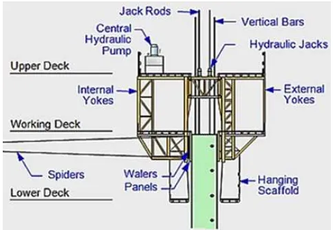
Figure 1. Slipform System Components
Slip-forming is a method of erecting silos by sliding up the whole form using an automated jacking device embedded in concrete and pouring continuously concrete, once concrete has developed early strength enabling it to stand by itself after placing. The essential elements of a Slipforming assembly are two parallel wall panels (about 1.2 m tall) supported by steel frames and horizontal yokes connected to hydraulic jacks as shown in Figure 1. After Slipform is
(1904 - 1905) in Kansas City for a rectangular grain tank that was approximately 25 to 30 feet high. In the late 1920s, a number of concrete structures were cast using a system of formwork that was moving during the placing of concrete. Early application of Slipform was limited to storage bins and silos with a constant thickness all over the wall height. The slipping process has evolved from small hand screwed jacks with threaded rods (in which everyone turned one-quarter of a turn at the sound of the foreman's whistle) to pneumatic jacks developed sometime in the 1930's and then hydraulic jacks developed in the early 1940's.Since the late 1950s, Slipform construction has come a long way; locomotion is accomplished by jacks climbing on smooth steel rods or pipes anchored at the base of the structure. Accordingly, the list of recent application expanded to include silos, towers cores, bridge piers, power plant cooling, chimney shafts, pylons, and the legs of oil rig platforms. As discussed above, it is convenient to consider the Slipform operation as consisting of three main elements; the concrete, the batching, transporting, placing, compacting and curing of the concrete and the shape, size and speed of the Slipform. Therefore the basic criteria for selecting slip-form as a formwork method will be project time; required speed; cross section uniformity and height; number of openings; and necessary stoppages in the height. Various attempts have been introduced in order to illustrate a basic understanding for the process of Slipforming using different types of methods,[20], [21], , [7] ,[22], [23] and [24] these studies implemented different types of analysis and approaches. The risk of modifying operational information and having mistaken should be eliminated. Consequently, a jointly prepared and implemented Method Statement is an essential tool to achieve efficiency and quality. Resulting from the previous it can be clear that a
common understanding of the process and efficient management are key factors for a successful operation.
3. Proposed Methodology
3.1. Overview
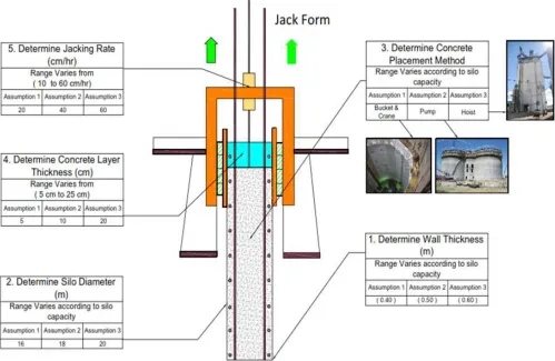
This research presents an integrated methodology for assisting in proper planning, estimating and prediction of construction duration generated by Slipform systems using EZstrobe software. To demonstrate the influence of Slipform technique implementations in construction industry, a Full Slip form Construction project was analyzed to estimate the proposed methodology’s prediction of construction durations. The proposed system focuses on the structure part of Silo construction for the following elements “Earthworks, Foundations and Walls”. A major benefit of using EZstrobe in simulation is that a simulation can be run for several times corresponding times of the duration of a project's completion will be automatically generated. The suggested model’s major parameters under study for modeling are shown in Fig. 3. Traditionally, the simulation model data inputs are those of the real project parameters i.e. (structure geometric, material quantities, resources, costs and etc.). Simulation model’s elements can be divided in to two main elements; Queues, that holds building quantities such as material quantities and resources amounts; and Combis that holds activity description and task durations. Queue’s data quantities source is generated from material quantity surveying, while Combis durations are generated from a mathematical process conducted on quantities and productivity rates by user. The case study presented in Section 4 illustrates further details of the operations simulation that is applied in this work.
Figure 3. Simulation Model Frame Work Inputs
3.2. Modelling Assumptions
Based on the suggested project conditions the following assumptions are made for simulation modeling:
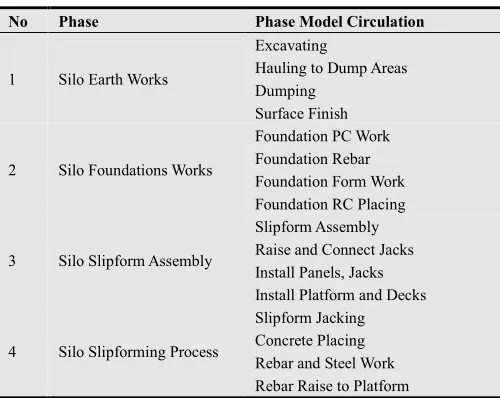
1. Model is based upon four stages of construction processes encountering Silo earthwork, Foundation work, Slipform Assembly and Slipforming works where each process covers the related activities as shown in Table 2.
2. In earthmoving operations, for general earthworks such as cut and dump operations, which were proposed in this study, the accuracy, degraded by multipath errors, was assumed to have been accepted and based upon a GPS system where surveying operations are not required [25].
3. Foundation work is excavated to a depth of 1.5 m below level for all instances and all scenario combinations as shown in sensitivity analysis.
4. Trucks used for hauling excavated earth to dumps are to have a capacity of 15 m3 per trip.
5. In foundation works, the concrete pouring is based upon a pump placement system with an average 3 to 4 m3/min.
6. For the Slipform assembly the total duration of assembly of Slipform is determined based upon 4 weeks to assemble.
7. The selection of placing system for the concrete has been studied based upon three different systems;
conventional crane and bucket delivery with adequate crane capacity, pump lines into hoppers on the deck and hoist placement system.
8. For the Slipforming works the Concrete placement method average duration varies between (7.5 min/m³), (3 min/m³) and (22.5 min/m³) for crane and Bucket placement, Pump placement and hoist placement respectively.
9. The lifting rate is determined with regard to the supply of all the components and the availability of manpower, so that interdependent activities can proceed without hold ups.
10.Uniform Jacking stroke rates varies based upon the concrete setting time, the Slipform hydraulic pump capacity therefore
11.Jacking stroke rates is specified from 10 cm/ hr to 60 cm/hr.
12.The interval between placing increments is limited to a maximum of 60 min in all of the Slipform resources combinations.
13.Concrete is placed in increments that result in uniform horizontal bands that are not so deep as to prevent proper vibration of the concrete and rising of trapped air to the surface which varies from 5 cm to 25 cm. 14.The frame work for the model input data is furtherer
Silo Diameter (SD) Wall Thickness (WT)
Concrete Placing Method (CP) Layer Thickness (LT)
Jacking Rate (JR)
15.Factorial design based on principle block is to be used for resources variation in sensitivity analysis with respect to 5 factors only which are (CP, LT, JR, SD and WT)
16.When estimating the daily productivity in the system, 60 min per hr was used for each 24 h during slip operation as no stoppage was allowed and work continued continuously.
Table 2. Simulation model sub models classification
No Phase Phase Model Circulation
1 Silo Earth Works
Excavating
Hauling to Dump Areas Dumping
Surface Finish
2 Silo Foundations Works
Foundation PC Work Foundation Rebar Foundation Form Work Foundation RC Placing
3 Silo Slipform Assembly
Slipform Assembly Raise and Connect Jacks Install Panels, Jacks Install Platform and Decks
4 Silo Slipforming Process
Slipform Jacking Concrete Placing Rebar and Steel Work Rebar Raise to Platform
4. Preliminary Prototype
As for this research case study, the preliminary prototype of the proposed integrated framework has been implemented and developed by using EZstrobe as the DES tool. Furtherer, to illustrate the framework model capabilities a Slipform case of study was chosen to apply the proposed software to a silo project located in Bandar Abbas, Iran for the Hormozghan cement factory project. The case of study chosen in current research is based upon Hormozghan cement factory project (Bandar Abbas, Iran). (Tarek Zayed 2008) It included Raw Meal Silos and towers with 6000-ton cement production per day. The silo was designed to store row material to feed a pre-heater tower that was used as a reserve for production line. Raw materials were transported from the Row Mill to the uppermost part of the silo. From there the row material flowed down a concrete cone, which distributed material to all outlets. All silos and towers of the cement factory were constructed using slip-form lifting system. Samarah Construction Co. (general civil contractor) performed the slip-forming part of this project. Silo has 16 meter- inner diameter, 50 cm thickness and 50 meters-height and a total Slipforming duration of 13.9 days. Concrete was poured using bucket and crane with a rate of 8 m³/hr. The data presented in Table 3 for time data collection is limited to the
Case study where for scenarios combination in sensitivity analysis the durations vary based on the scenario combination of resources
4.1. Simulation Model Input Data
Simulation model input data are inserted manually by the user in two main modeling elements as described earlier; first: Queue(s) elements input data that hold materials, labor and equipment quantities; and Second: Combi(s) elements input data that hold activities durations and attributes.
4.1.1. First; Material and Resources Quantities
Silo material quantities are estimated using traditional Quantity survey where QS estimates quantities from project drawings and provides the relevant parameters (such as length, width, height, area, and volume) needed to perform the quantity takeoffs of the weight (in tons) of steel, the area (m) of the forms, and the volume (m3) of concrete for each construction element (i.e., column, beam, wall, and slab). Table. 4 present a quantity table that summarizes the quantities of materials that will be needed for the tasks in the project. Moreover Resources can be categorized in to two main groups Labor and Equipment. Both labor and equipment amounts are shown in table 5 where it presents the resource type, resource name and quantity.
4.1.2. Second; Activity Durations
In order to create the durations input data, each project activity is assigned to duration with a certain distribution. Activities durations are shown in Table 6 where it presents the category of activity, activity name, type of duration and assigned duration. It is noted that due to the uncertainties in the industry both uniform and triangular distributions owns the majority of duration types as illustrated in the aforementioned table. Based on project case study and best practices the duration’s types and distributions were chosen in the proposed model.
4.2. Simulation Model Development
An EZstrobe network for a full Slipform project has been created and developed. This network indicates the construction tasks, the logical links between tasks, and the resources required for the project. Specifically, the following sub models are encountered through building the simulation model the four models are connected through a fusion Queue for ease of studying each sub model. In addition, crews’ formulation for concrete pouring, steel rebar and formwork crews are involved.
first need receives the highest priority for being served. The following section illustrates the DES model phases.
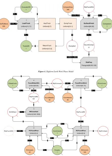
4.2.1. Silo Earth Works Model
4.2.1.1. Model Description
Silo Earth works Model describes Earth works for the Slipform project, where it encounters the excavation works, hauling excavated soil to dumps and dumping, moreover the sub model shows compacting works for the excavated area. Silo earth work Sub model process is furtherer illustrated in Figure 4; amount of quantities and resources are shown in tables 4 and 5, while durations are shown in table 6.
4.2.1.2. Model Circulation
a. Silo ground area is excavated with required dimensions and to required level using a GPS machine guidance system where no surveying is required and accuracy is accepted.
b. Excavated material is hauled by truck to nearest dump, unloads and returns back to load excavated soil.
c. After excavation, the area is compacted using a compactor and level is ready for Foundation works. d. Equipment used for earth work is (Truck, Loader, and
Compactor) with the following activities durations Table 5.
4.2.2. Foundations Works Model
4.2.2.1. Model Description
Foundations Works Model describes typical foundation works for the Slipform project, where it encounters the plain concrete pouring under foundations, steel and rebar works for foundations, form work and Reinforced concrete pouring for foundations. Foundations Work Sub model process is furtherer illustrated in Figure 5, amount of quantities and resources are shown in tables 4 and 5, while durations are shown in table 6.
4.2.2.2. Model Circulation
a. Model starts with Pouring P.C for foundations on required level with thickness 0.15 m using the following resources (Pump placing System, Concrete Crew and PC Concrete Available). Placed concrete is left for 24 hours for final Hardening.
b. The Rebar and steel work starts after the finish of the PC hardening activity using the following resources (Steel crew and Rebar available)
c. After Rebar and steel work finish, the Formwork starts using the following resources (Foundation form work crew and Form work Available)
d. After Form work finish the RC pouring starts using the following resources (Pump placing System, Concrete Crew and RC Concrete Available)
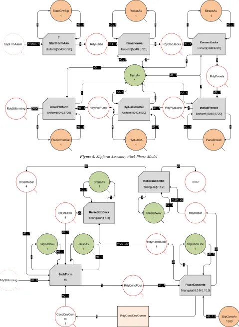
4.2.3. Slipform Assembly Works Model
4.2.3.1. Model Description
Slipform Assembly Works Model describes the Slipform assembly process, where it encounters raising the jacks and
connecting it using horizontal straps, installing panels, installing hydraulic jacks and platforms. Slipform assembly Sub model process is furtherer illustrated in Figure 6, amount of quantities and resources are shown in tables 4 and 5, while durations are shown in table 6.
4.2.3.2. Model Circulation
a. Slipform assembly starts with raising forms using Jacks and connecting it using Horizontal straps, after that Panels are installed using the Panels available, Then Hydraulic jacks are installed using hydraulic jacks available,
b. Finally Platforms Upper, Lower and working decks are installed using material available.
c. Activities for each activity are based upon average total duration for Slipform assembly divided by the number of activities. As Slipform assembly varies from 3 to 4 weeks based upon shape and geometry of silo structure
4.2.4. Slip Forming Works Model
4.2.4.1. Model Description
Slip forming Works Model describes the Slip forming operation sequence for Silo construction, the sub model encounters jacking forms based on jacking rates and layer thickness and concrete setting time, moreover concrete placement, rebar work and raising rebar to working decks. Slip forming Sub model process is furtherer illustrated in Figure 7; amount of quantities and resources are shown in tables 4 and 5, while durations are shown in table 6.
4.2.4.2. Model Circulation
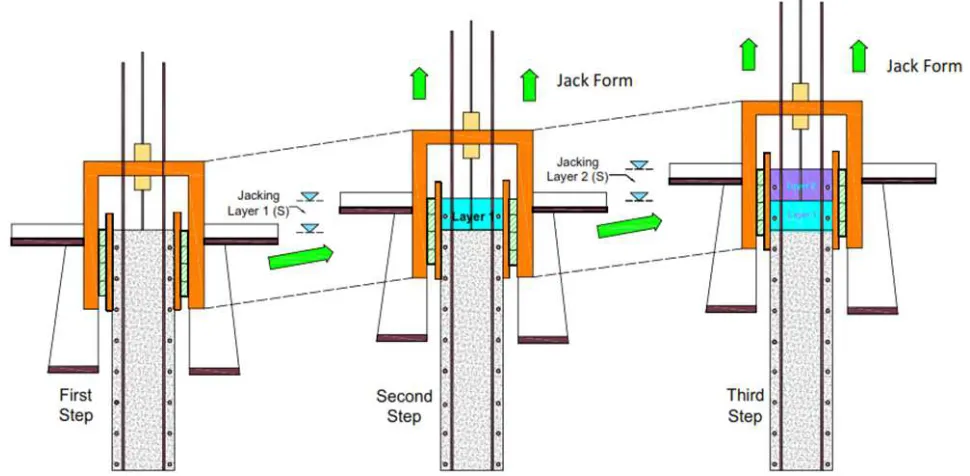
a. The Slip forming model starts with the Jacking activity where jacking varies as shown in mentioned earlier from 10 cm/hr to 60 cm/hr; one jack height is almost 2 inch (5cm). Jacking activity duration depends mainly on the Slipform mechanical capacity, concrete setting time and concrete layer thickness. Jacking rate durations based on Layer thickness.
b. Then, Concrete is poured based on the pouring method which varies from Crane and buckets to Pumps and also depends on the silo cross section and jacking step. c. When form is raised up to 20 cm, horizontal rebar is
installed and Slipform gets ready for next jacking step. d. Repeat steps 2 to 5 until the completion of concrete silo. e. When form is raised up to 3 m the tower crane lifts
reinforcements and embedded to working deck.
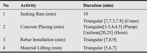
Table 3. Case of Study Durations
No Activity Duration (min)
1 Jacking Rate (min) 10
2 Concrete Placing (min)
Triangular [7,7.3,7.8] (Crane) Triangular[3.5,4,4.5] (Pump) Uniform[20,25] (Hoist) 3 Rebar Installation (min) Triangular [7,8,9]
Table 4. Silo Project Material Quantities
ID Phase Material Type Material Description Unit Quantity
1 Earthworks Soil Amount of Excavated Soil m³ 555
Soil Amount of Compacted Soil m² 340
2 Foundation Works
Plain Concrete Foundation PC Beneath Raft m³ 45
Reinforced Concrete Foundation RC Raft m³ 340
Steel Raft Rebar Amount ton 50
Formwork Raft Formwork Amount m² 60
3 Assembly Works
Slipform Yokes Set for Slip Assembly Set 1
Slipform Straps Set for Slip Assembly Set 1
Slipform Panels Set for Slip Assembly Set 1
Slipform Platforms Set for Slip Assembly Set 1
4 Slipforming Works Reinforced Concrete Slipform Continuous Concrete Crew Number m³ 1300
Steel Slipform Continuous Steel Crew Number ton 100
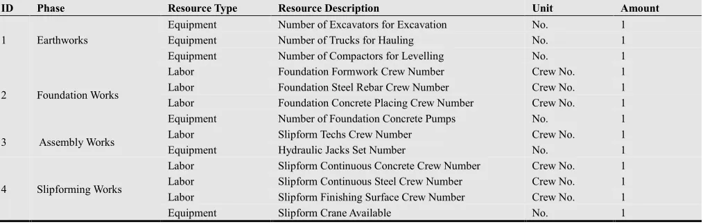
Table 5. Project Resources Amounts
ID Phase Resource Type Resource Description Unit Amount
1 Earthworks
Equipment Number of Excavators for Excavation No. 1
Equipment Number of Trucks for Hauling No. 1
Equipment Number of Compactors for Levelling No. 1
2 Foundation Works
Labor Foundation Formwork Crew Number Crew No. 1
Labor Foundation Steel Rebar Crew Number Crew No. 1
Labor Foundation Concrete Placing Crew Number Crew No. 1
Equipment Number of Foundation Concrete Pumps No. 1
3 Assembly Works Labor Slipform Techs Crew Number Crew No. 1
Equipment Hydraulic Jacks Set Number No. 1
4 Slipforming Works
Labor Slipform Continuous Concrete Crew Number Crew No. 1
Labor Slipform Continuous Steel Crew Number Crew No. 1
Labor Slipform Finishing Surface Crew Number Crew No. 1
Equipment Slipform Crane Available No. 1
Table 6. Project Activities Durations
ID Phase Activity Name in DES Activity Type Duration Type Duration [min]
1 Earth Work
LoadTruck Combi Uniform [10,11]
HaulTruck Normal Uniform [5,7]
DumpTruck Normal Uniform [0.5,1]
ReturnTruck Normal Uniform [4.5,5]
SitePrep Combi Triangular [60,90,120]
SurfaceFinish Combi Uniform [60,90]
2 Foundation Work
PCFoundPour Combi Uniform [3,4]
WtConcHard Combi Uniform [1440,1600]
FoundRebarWrk Combi Uniform [100,120]
FoundFormWork Combi Uniform [60,75]
RCFoundPour Combi Uniform [3,4]
3 Slipform Assembly Work
StartFormAss Combi Uniform [5040,6720]
RaiseForms Combi Uniform [5040,6720]
ConnectJacks Combi Uniform [5040,6720]
InstallPanels Combi Uniform [5040,6720]
HydJacksInstall Combi Uniform [5040,6720]
Install Platform Combi Uniform [5040,6720]
4 Slip forming Model
JackForm Combi Deterministic 10
PlaceConcrete Combi Triangular [8.5,9.5,10.5]
RebarandEmbd Combi Triangular [7,8,9]
Figure 4. Slipform Earth Work Phase Model
Figure 6. Slipform Assembly Work Phase Model
4.3. Scenarios Factor’s Configurations
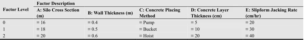
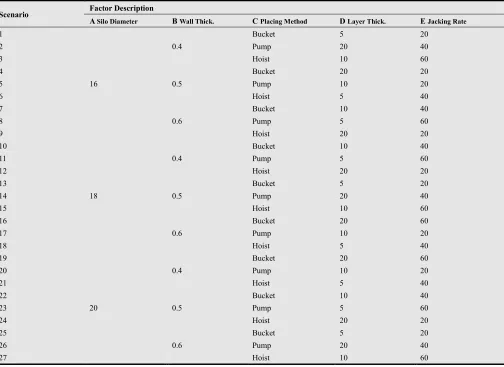
Factors generally influence the Slipform construction duration includes; silo diameter, wall thickness, and concrete placing method, jacking rate and layer thickness. A series of experiments is performed on the 5 process factors to investigate their effect on the productivity rate and project duration, study the interaction among the factors and determine the most effective factor. A fractional factorial experiment approach using 5 factors each at three levels has been adopted. Table 7 presents the three levels of each factor under study as, three diameters of silo cross section (16, 18 and 20) m; three thicknesses of walls (0.4, 0.5 and 0.6) m; three types of concrete placing methods (Pump, Bucket and Hoist) m; three thicknesses of concrete layer pouring (5, 10 and 20) cm and three values of jacking rates (20, 30 and 40) cm/hr. Resulting in twenty seven experiment as 1/9 fractional factorial of 3^5 design based on the Principle block. The configurations of the twenty seven scenarios for the 5 factors selected for investigation together with the three levels for factorial design are given in Table 8. The levels of each factor were selected on the basis of good performance deduced from prior testing; production of practical and economic combinations.
5. Simulation Sensitivity Results
Based upon the aforementioned scenarios configurations, 27 simulation alternatives associated with various resource allocation strategies were produced. Table 9 presents the various values of model response to each scenario configuration as results (1) and (2) for total project duration and Slipforming duration. From this table it can be noted that all responses values showed Slipforming duration and total project duration comparable to that of case study results. In order to analyze the results and determine each parameter’s significance, a set of steps are performed. First: calculate the average effect of factors levels on both results as shown in table 9. The average effect is calculated as the average of the
9 scenarios configuration with the same factor level for the required factor. I.e. for the average impact of level (0) of Factor (A) on Slipforming duration is calculated as following = (15.7+8.1+19.7+17+14+25.4+13.2+7.8+34.8)/9 = 17.3 days, this example is highlighted in table 10. Second: the degree of effectiveness of the three factors under study for total duration and Slipform duration are calculated and illustrated as shown in tables 11 and 12 respectively. The percentage of effectiveness is the result of dividing the difference between highest and lowest response for each factor by the sum of differences as shown in aforementioned. I.e. the effective percentage of factor A “Silo Cross Section” is due to dividing the difference between Highest project duration (58.2) and lowest project duration (56.6) for the same factor by the sum of differences “45.1” =(58.2-56.6)/45.1 = 3.6 % as highlighted in table 11.
Sensitivity analysis results are presented graphically in Figures 8 and 9 where these figures show the effective degree of each factor on both total project duration and Slipforming duration. Consequently, the highest effective degree on both results points to the most important factor that should be carefully considered when planning Slipforming operations. Duration reduction or increase is directly influenced by the effective degree of each factor as shown in aforementioned figures. Further figures and results analysis shows that the most effective factor among the five factors under study is Factor C: Concrete Placing Method, where in both figures factor C holds the highest proportion of the chart, followed by Factor E: Slipform Jacking Rate, followed by Factor B: Wall Thickness, then followed by Factor A: Structure Cross Section, Lastly Factor D: Concrete Layer Thickness. Although the arrangement of factor’s effective degree on both results follows the same pattern, it is notable to mention that the factors effect is highly observed on the Slipforming duration rather than the total project duration. Generally, concrete placing method has the most significant effect on both results, while the concrete layer thickness has the lowest effect on both results.
Table 7. Simulation Configuration Levels
Factor Level
Factor Description A: Silo Cross Section
(m) B: Wall Thickness (m)
C: Concrete Placing Method
D: Concrete Layer Thickness (cm)
E: Slipform Jacking Rate (cm/hr)
0 ≡ 16 ≡ 0.4 ≡ Pump ≡ 5 ≡ 20
1 ≡ 18 ≡ 0.5 ≡ Bucket ≡ 10 ≡ 30
2 ≡ 20 ≡ 0.6 ≡ Hoist ≡ 20 ≡ 40
Table 8. Factors levels and values
Scenario Factor Level
A Silo Diameter B Wall Thick. C Placing Method D Layer Thickness E Jacking Rate
1 0 0 0 0 0
2 0 0 1 2 1
3 0 0 2 1 2
4 0 1 0 2 2
Scenario Factor Level
A Silo Diameter B Wall Thick. C Placing Method D Layer Thickness E Jacking Rate
6 0 1 2 0 1
7 0 2 0 1 1
8 0 2 1 0 2
9 0 2 2 2 0
10 1 0 0 1 1
11 1 0 1 0 2
12 1 0 2 2 0
13 1 1 0 0 0
14 1 1 1 2 1
15 1 1 2 1 2
16 1 2 0 2 2
17 1 2 1 1 0
18 1 2 2 0 1
19 2 0 0 2 2
20 2 0 1 1 0
21 2 0 2 0 1
22 2 1 0 1 1
23 2 1 1 0 2
24 2 1 2 2 0
25 2 2 0 0 0
26 2 2 1 2 1
27 2 2 2 1 2
Table 8. (Continue).
Scenario Factor Description
A Silo Diameter B Wall Thick. C Placing Method D Layer Thick. E Jacking Rate
1
16
0.4
Bucket 5 20
2 Pump 20 40
3 Hoist 10 60
4
0.5
Bucket 20 20
5 Pump 10 20
6 Hoist 5 40
7
0.6
Bucket 10 40
8 Pump 5 60
9 Hoist 20 20
10
18
0.4
Bucket 10 40
11 Pump 5 60
12 Hoist 20 20
13
0.5
Bucket 5 20
14 Pump 20 40
15 Hoist 10 60
16
0.6
Bucket 20 60
17 Pump 10 20
18 Hoist 5 40
19
20
0.4
Bucket 20 60
20 Pump 10 20
21 Hoist 5 40
22
0.5
Bucket 10 40
23 Pump 5 60
24 Hoist 20 20
25
0.6
Bucket 5 20
26 Pump 20 40
Table 9. Simulation Results Values.
Scenario
Factor Description Simulation Results
A
Silo Diameter B
Wall Thickness C
Placing Method D
Layer Thickness E
Jacking Rate (1)
Total Project Duration (Day)
(2) Slipforming Duration (Day) 1
16
0.4
Bucket 5 20 56.3 15.7
2 Pump 20 40 47.7 8.1
3 Hoist 10 60 58 19.7
4
0.5
Bucket 20 20 55 17
5 Pump 10 20 52.6 14
6 Hoist 5 40 65.6 25.4
7
0.6
Bucket 10 40 52.3 13.2
8 Pump 5 60 47.4 7.8
9 Hoist 20 20 75.6 34.8
10
18
0.7
Bucket 10 40 50.7 11.1
11 Pump 5 60 45.6 6.7
12 Hoist 20 20 67.5 28.4
13
0.8
Bucket 5 20 56.2 17.8
14 Pump 20 40 48.8 9.3
15 Hoist 10 60 64.6 26.2
16
0.9
Bucket 20 60 51.2 12.4
17 Pump 10 20 53.4 15.3
18 Hoist 5 40 71.1 32.5
19
20
1
Bucket 20 60 48.1 10
20 Pump 10 20 53.2 14
21 Hoist 5 40 65.8 25.2
22
1.1
Bucket 10 40 52.3 13.4
23 Pump 5 60 45.7 8
24 Hoist 20 20 74.7 36.7
25
1.2
Bucket 5 20 60 20.3
26 Pump 20 40 49.7 10.6
27 Hoist 10 60 74.1 33.8
5.1. Significance and Discussions
While this research results can directly define the most important factors that should be carefully considered when a new project is under study in the preliminary phase, the interaction between factors based upon the factors levels are presented to furtherer illustrate the factors significance from the obtained results as shown in figures 10 and 11 for total project duration and Slipforming duration. Results show that among the five factors under study, the most significant factor that effects both Slipforming duration and total project duration is the concrete placing method, followed by the jacking rate, then the structure wall thickness, structure cross
section and finally the concrete layer thickness.
in this research can be adopted to forecast project time for other Slipform project types and/or in other locations. The
current study focuses on the aspect of duration. Cost criteria may also be added to evaluate various construction strategies.
Table 10. Average effect of factors on sensitivity results
Factor Factor Level Factor Value Average Factor Effect on Simulation Results
Total Project Duration (Days) Slipforming Duration (Days)
A: Silo Cross Section (m)
0 16 56.7 17.3
1 18 56.6 17.7
2 20 58.2 19.1
B: Wall Thickness (m)
0 0.4 54.8 15.4
1 0.5 57.3 18.6
2 0.6 59.4 20.1
C: Concrete Placing Method
0 Bucket 53.6 14.5
1 Pump 49.3 10.4
2 Hoist 68.6 29.2
D: Concrete Layer Thickness (cm)
0 5 57.1 17.7
1 10 56.8 17.9
2 20 57.6 18.6
E: Slipform Jacking Rate (cm/hr)
0 20 67.2 23.8
1 40 56.0 16.5
2 60 48.3 13.8
Table 11. Effectiveness percentage of factors on total project duration
Factor Factor Level Factor Value Total Project Duration (Days)
Difference (High PD - Low PD)
Effectiveness Percentage (%)
A: Silo Cross Section (m)
0 16 56.7
1.6 3.6%
1 18 56.6
2 20 58.2 *hint = 58.2-56.6 *Illustration = 1.6/45.1
B: Wall Thickness (m)
0 0.4 54.8
4.7 10.3%
1 0.5 57.3
2 0.6 59.4
C: Concrete Placing Method
0 Bucket 53.6
19.2 42.6%
1 Pump 49.3
2 Hoist 68.6
D: Concrete Layer Thickness (cm)
0 5 57.1
0.8 1.7%
1 10 56.8
2 20 57.6
E: Slipform Jacking Rate (cm/hr)
0 20 67.2
18.9 41.8%
1 40 56.0
2 60 48.3
Sum 45.1 100%
Table 12. Effectiveness percentage of factors on Slipforming duration
Factor Factor Level Factor Value Total Project Duration (Days)
Difference (High PD - Low PD)
Effectiveness Percentage (%)
A: Silo Cross Section (m)
0 16 17.3
1.8 5.0%
1 18 17.7
2 20 19.1
B: Wall Thickness (m)
0 0.4 15.4
4.6 12.9%
1 0.5 18.6
2 0.6 20.1
C: Concrete Placing Method
0 Bucket 14.5
18.8 52.1%
1 Pump 10.4
2 Hoist 29.2
D: Concrete Layer Thickness (cm)
0 5 17.7
0.9 2.4%
1 10 17.9
2 20 18.6
E: Slipform Jacking Rate (cm/hr)
0 20 23.8
9.9 27.6%
1 40 16.5
2 60 13.8
Figure 8. Effective percentage of each factor on total project duration.
Figure 9. Effective percentage of each factor on Slipforming duration.
Figure 10. Interaction of Factors Values and Levels on Slipforming Duration
Figure 11. Interaction of Factors Values and Levels on total project Duration
6. Conclusions
The responsive use of discrete event simulation model for estimating and predicting preliminary schedule duration of Slipform projects application to concrete silos is presented in this research. The EZstrobe simulation software was used to develop the model. This model is considered a full slip form project and operation model with the aforementioned capabilities. The proposed model is divided into four model phases for the Slipform operation, Silo earthworks, Foundation works, Slipform Assembly and Slipforming process. Simulation is an ideal decision– support tool because it allows quick and data-rich exploration of “what if” scenarios at any given point in time. Several factors have been considered through the model for predicting productivity such as, Silo diameter, wall thickness, placing method, concrete layer thickness and Jacking rate of forms. The models are tested and show high accuracy in predicting slip-form productivity as by validating proposed Slipform model with case study it showed a robust of 98.7%. The output of this research can helpfully assist practitioners and researchers in the field of construction simulation and Slipforming, because they provide a planning and scheduling tool for slip-form operation in silo construction. Moreover computational results show that the use of this approach can significantly help improving the efficiency of the production system. In addition to simulation models that are flexible enough to modify and add more features and develop a reliable schedule of Slipforming operation suitable for a specific project by optimizing various operation parameters.
Acknowledgements
I would like to extend my appreciation to BEC Slipform System Company particularly Mr. Eddie Williams (Managing Director), for his great help and professional advice in current research.
References
[1] Weizhuo Lu, Thomas Olofsson. "Building information modeling and discrete event simulation: Towards an integrated framework." Automation in Construction, 2014: 73-83.
[2] Halpin, D., and Riggs. Planning and analysis of construction operations. New York. Wiley, 1992.
[3] Jürgen Melzner, Sebastian Hollermann, Hans-Joachim Bargstädt. "Detailed Input data Source for Construction Process Simulation." The Third International Conference on Advances in System Simulation. Bauhaus-University Weimar, Germany, 2011.
[5] I-Chen Wu, André Borrmann, Ulrike Beißert, Markus König, Ernst Rank. "Bridge construction schedule generation with pattern-based construction methods and constraint-based simulation." Advanced Engineering Informatics, 2010: 379-388.
[6] K.T. Fossa, A. Kreiner, J. Moksnes. "Slipforming of advanced concrete structures." Tailor Made Concrete Structures – Walraven & Stoelhorst , 2008.
[7] M.R. Sharifi, S. Baciu and T. Zayed. "Slip-Form Productivity Analysis for Concrete Silos." International Construction Specialty Conference. Calgary, Alberta, Canada, 2006.
[8] S. Abourizk, D. W. Halpin, and J. D. Lutz,. "State of the art in construction simulation." Proceedings of the 1992 Winter Simulation Conference. Arlington, VA, 1992. 1271-1277.
[9] Zayed, T. and Halpin, D. "Simulation Of Concrete Batch Plant Production." Journal of Construction Engineering and Management, 2001: 132-141.
[10] Kannan, G., et al . "A framework for incorporating dynamic strategies in earthmoving simula-tions. In WSC’97: Proceedings of the 1997 Winter Simulation Conference, Atlanta, Ga., 7–10 December 1997. ." 1997.
[11] Ericsson, U. Diffusion of Discrete Event Simulation in Swedish Industry, One way to an Increased Understanding, PhD Thesis. Gothenburg, Sweden: Chalmers University of Technology, 2005.
[12] A. Skoogh, T. Perera, B. Johansson. "Input data management in simulation – Industrial practice and future trends." Simulation Modelling Practice and Theory, 2012: 181-192.
[13] Law, A. and Kelton, D. 1982. Simulation modeling and analysis, McGraw-Hill, New York.
[14] Jahangirian et al. "Simulation in manufacturing and business." European Journal of Operational, 2010: 1-13.
[15] Wang, Halpin. "Simulation experiment for improving construction processes." Proceedings of the 2004 Winter Simulation Conference, Washington, D.C. 2004.
[16] AbouRizk, S. "Role of simulation in construction engineering and management." Journal of Construction Engineering and management, 2010: 1140-1153.
[17] Martinez, J.C. STROBOSCOPE: State and Resource Based Simulation of Construction Process, Doctoral Dissertation. Ann Arbour, 1996.
[18] Martinez, J.C. "EZstrobe -- general-purpose simulation system based on activity cycle diagrams." Proceedings of 1998 Winter Simulation Conference. 1998. 341 – 348.
[19] Fossa, K. T. "Slipforming of Vertical Concrete Structures. PhD Thesis." Norway, 2001.
[20] Anagnostopoulos, Christos. Application of the maturity method in Slipforming operations. 2003.
[21] T. Zayed “Slip-Form Application to Concrete Structures” Journal of Construction Engineering and management, 2008
[22] Kim, H. Mechanical Characteristics of GFRP Slip Form. Ph.D. Thesis, Hanyang University, 2012.
[23] Hyejin Yoon, Won Jong Chin, Hee Seok Kim, Young Jin Kim. "A Study on the Quality Control of Concrete during the Slip Form Erection of Pylon." Engineering, 2013: 647-655.
[24] Hanna. Concrete Formwork Systems. New York: Marcel Dekker, 1998.
[25] H.Khalik et al. "Simulation Analysis For Productivity And Unit Cost By Implementing (Gps) Machine Guidance In Road Construction Operations In Egypt." 2012.
Biographies
Hesham Abdel Khalik Professor of Construction Engineering and Management, Alexandria University, Egypt Graduated from Faculty of Engineering, Alexandria University, Egypt, 1984. He has his Ph.D. in Construction Engineering and Management from Alexandria University in 1994. He worked as Visiting Assistant Professor in University of Lexington, KY in 1996-1997 and worked in King Saud University. His email address is: [email protected]
Remon Fayek Aziz Assistant Professor in the Department of Structural Engineering, Faculty of Engineering, Alexandri University, Alexandria, Egypt.
the B.Sc. degree in Civil Engineering from Faculty of Engineering, Alexandria University, Alexandria, Egypt, in 1998. M.Sc. and the Ph.D. degrees in Construction Engineering and Management from Department of Structural Engineering, Faculty of Engi Alexandria University in 2004 and 2010, respectively. His research interests include the management and control of construction projects, project monitoring and risk mitigation, asset management, and smart optimizations. He has consulted widely with government agencies and the construction industries. His email address is [email protected]
Assistant Professor in the Department of Structural Engineering, Faculty of Engineering, Alexandria University, Alexandria, Egypt. He received the B.Sc. degree in Civil Engineering from Faculty of Engineering, Alexandria University, Alexandria, Egypt, in 1998. M.Sc. and the Ph.D. degrees in Construction Engineering and Management from Department of Structural Engineering, Faculty of Engineering, in 2004 and 2010, respectively. His research interests include the management and control of construction projects, project monitoring and risk mitigation, asset management, and smart th government agencies and His email address is:
Mohamed
Assistant
Construction Engineering and Management, Faculty of Engineering, Pharos University in Alexan
degree in Civil Engineering from Faculty of Engineering, Alexandria University, Alexandria, Egypt, in
Construction Engineering and Management from Department of Structural Engineering, Faculty of Engineerin
University, Alexandria, Egypt, in [email protected].