Evaluation of Adhesion Strength of Er
2
O
3
Coating Layer for an
Advanced Breeding Blanket System Applied to Thermal Cycles
using Nano-Scratch Method
Yoshimitsu HISHINUMA, Teruya TANAKA, Kenji MATSUDA
1), Daisuke TAKADA
2),
Toshihiro HOSEN
2), Akio SAGARA and Takeo MUROGA
National Institute for Fusion Science, Toki, Gifu 509-5292, Japan
1)University of Toyama, Toyama 903-8555, Japan 2)RHESCA Co.,Ltd, Hino, Tokyo 191-0011, Japan
(Received 7 August 2013/Accepted 1 December 2013)
The electrical insulator and hydrogen permeation barrier coatings are important materials to realize the liquid metal and molten-salt typed breeding blanket systems. We found that erbium oxide (Er2O3) is one of the
promis-ing materials as the electrical insulator and hydrogen permeation restraint coatpromis-ings. Establishpromis-ing the mechanical property evaluation method for these coating is extremely important to certify the durability of coating material in the blanket systems. The adhesion strength property, which is one of the key mechanical properties of coating materials, was investigated using the nano-scratch method. From the results, it was found that the nano-scratch test was able to evaluate the adhesion strength of the Er2O3coating synthesized by the Metal Organic Chemical
Vapor Deposition (MOCVD) process with high reproducibility. Furthermore, the adhesion strength of the Er2O3
coating before and after thermal cycling was evaluated using this method. The adhesion strength after 50 thermal cycles at 700◦C was kept around 70% compared with that before thermal cycling.
c
2014 The Japan Society of Plasma Science and Nuclear Fusion Research
Keywords: blanket system, Er2O3coating, scratch test, adhesion strength, thermal cycling
DOI: 10.1585/pfr.9.1405004
1. Introduction
In the magnetic confinement fusion reactor as the sus-tainable energy source, an advanced breeding blanket is perferable system to realize high energy conversion effi -ciency and high tritium breeding ratio (TBR). The liquid metal (Li and Pb-Li) and molten-salt (FLiBe and FLiNaK) typed breeding blankets are promising as advanced blanket systems. However, critical problems of these systems were pointed out for the application to the magnetic confine-ment fusion reactors. These include restraints by the Mag-neto Hydrodynamic (MHD) pressure drop for Li and Pb-Li systems, and the tritium permeation leakage for Pb-Li and molten-salt systems, respectively [1, 2]. An electrically in-sulating coating with ceramics material such as oxides and nitrides is one of the attractive methods to break off elec-tromagnetic force inducing the MHD pressure drop. D.L. Smithet al. reported that modest electrical resistivity of 104Ωm is required in order to restrain the MHD pressure drop in the thin coating below 1µm [3]. A coating with ce-ramic materials will also be effective to suppress to 1/1000 the hydrogen permeation from molten-salt such as FLiBe and FLiNaK [4]. These ceramic coating materials will be absolutely necessary to realize the various advanced blan-ket systems such as liquid Li, Pb-Li and molten-salt typed
author’s e-mail: [email protected]
systems.
Some ceramic materials such as CaO, Y2O3, CaZrO3,
AlN and Er2O3have been studied as the candidate
mate-rials for the insulating coating [5, 6]. Er2O3 was selected
as one of the candidate materials for the insulator coat-ing for reduccoat-ing the MHD pressure drop because of high compatibility with liquid Li and high electrical resistiv-ity at higher temperature [6]. Furthermore, it was found that Er2O3 layer can significantly suppress hydrogen
per-meation. Thus, we are convinced that Er2O3 is a
suit-able coating material as not only the electrical insulator but also tritium leakage barrier materials. Various tech-nologies have therefore been developed for coating Er2O3
layer on blanket structural materials [6–9]. Chemical va-por deposition (CVD) is a potential method for large area of complex-shaped coating, and metal organic vapor depo-sition (MOCVD) process was applied as a new technology for Er2O3 coating on broad and complicated shaped
com-ponents including duct interiors [10–13].
Characterization of the Er2O3 coating has been
car-ried out by hardness and microstructure. Although adhe-sion to the substrate is one of the key properties of the ce-ramic coatings, systematic evaluation of the properties of Er2O3coatings has not been carried out partly because the
methodology of evaluation has not been established. To clarify adhesion strength of ceramic coating material under
c
2014 The Japan Society of Plasma
slit in the hard coating. In addition, the quantitative adhe-sion evaluation of multi-coating layer could not be carried out using cross-cut adhesion and pull offmethods. Further-more, these methods are only available when the adhesion strength of coating layer is weaker than that of the separa-tion tape and bond.
In 1997, the scratch method was made applicable to the case which needs much larger external forces to sepa-rate from a substsepa-rate like the case of hard coating, and was qualified to the JIS R3255. In the nano-scratch method, a diamond stylus pressed on the surface of coating layer, scratched the surface of the coating layer with an increas-ing applied dynamic load. Usincreas-ing this scratch mechanism, the adhesion evaluation is possible on not only single layer but also multi-layered samples. Further advantage of the scratch method is that larger dynamic load can be applied to the hard coating layer compared with the cross-cut adhe-sion and pull offmethods. This method has been applied to the inspection of the car paint-films, cutware tool and the diamond like carbon (DLC) film and so on [16].
In this paper, the adhesion strength measurement of MOCVD processed Er2O3 thin coating layer on the metal
substrate was carried out using nano-scratch method for the purpose of establishing adhesion strength evaluation for thin coating layers. In this case, the stainless steel (SUS316) was used as the substrate for demonstrating the present technology using a well-characterized mate-rial instead of low activation candidate matemate-rials for fusion blanket such as Reduced Activation Ferritc/Martensitic Steel (RAFM), Oxide Dispersive Strengthen (ODS) steel and vanadium alloys. In addition, we also prepared the MOCVD processed Er2O3coating after thermal cycles for
several times between room temperature and 700◦C in Ar atmosphere. The changes of microstructure and adhesion strength of Er2O3coating layer by the thermal cycling were
investigated.
2. Samples and Experimental
Proce-dure
2.1
Preparation
of
MOCVD
processed
Er
2O
3coating with thermal cycling
The Er2O3 coating layers were formed on SUS 316
disk plate using MOCVD apparatus in National Institute for Fusion Science (NIFS). The MOCVD apparatus in
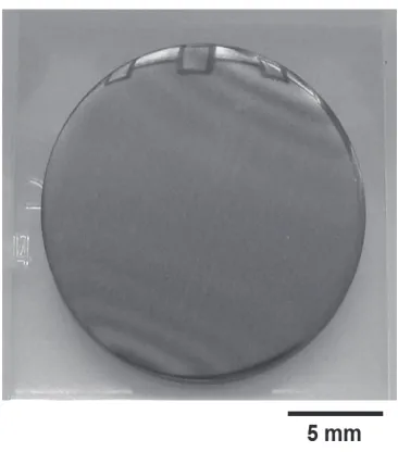
Fig. 1 Typical photograph of Er2O3 coating on SUS 316
sub-strate via MOCVD process.
NIFS and the MOCVD process was described in detail in Refs. [10–13]. The dimension of SUS 316 disk is 17 mm in diameter and 1 mm in thickness. The deposition tem-peratures and time were fixed to 450, 475 and 500◦C and 2 hours. Figure 1 shows typical optical image of MOCVD processed Er2O3on SUS 316 substrate. The change of
mi-crostructure in Er2O3 coating layer was characterized by
XRD analysis and SEM and TEM observations. Accord-ing to the XRD pattern of the coatAccord-ing layer, all of main peaks were identified as a Er2O3phase. TEM image of the
cross-sectional area in Er2O3 coating layer via MOCVD
process is shown in Fig. 2. The thickness of Er2O3
coat-ing layer was about 700 nm. The layer was grown densely like columnar grain texture. In the boundary of Er2O3and
SUS 316 substrate, no macroscopic defect such as crack and separation was observed.
Thermal cycling tests were carried out for some sam-ples. The thermal cycling temperature was fixed at 700◦C. This temperature was assumed as the operation condition of the liquid metal blanket systems such as Li [17] and Pb-Li [18]. The samples were set into the temperature plateau region of the electrical furnace and were heated up to 700◦C of the peak temperature under Ar gas flowing. The temperature was elevated to peak temperature at a rate of 700◦C/hour and then held for 1 hour, followed by fur-nace cooling to 50◦C. The number of thermal cycling was 10, 30 and 50. Figure 3 shows typical temperature history during 30 times of the thermal cycling.
The changes of microstructure and adhesion strength on the MOCVD processed Er2O3coating on SUS 316
Fig. 2 TEM image of cross-sectional area in Er2O3coating layer
on SUS 316 substrate via MOCVD process.
Fig. 3 Temperature history of the Er2O3coating sample during
30 times of thermal cycling.
2.2
The measurement principle of the
nano-scratch method
In order to evaluate adhesion strength of the MOCVD processed Er2O3coating samples before and after thermal
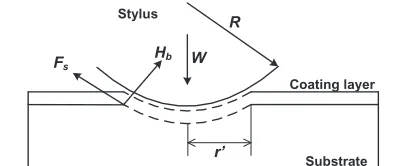
cycling, scratch tests were carried out using nano-layer scratch instrument (CSR-2000: RHESCA Co.,Ltd). The configuration and interaction between the diamond scratch stylus tip and surface of coating layer is shown in Fig. 4. In these tests, the surface of the coating layer is scratched by a vibrating diamond stylus tip of a given cur-vature radius mounted on an elastic arm while the stylus is being lowered in the coating thickness direction. The elas-tic arm is deformed because of the lowering movement of the stylus, resulting in an increased load force to the coat-ing layer applied by the stylus.
According to the formula of Benjamin and Weaver, the relationship between the dynamic load (W) applied by the stylus to the coating and the shearing stress (Fs) on the
interface the coating layer and substrate have established
Fig. 4 The configuration and interaction between the diamond scratch stylus and surface of the coating layer.
as the following Eq. (1) [19],
Fs=Hb/
(πR2H
b/W)−1, (1)
whereR is the curvature radius of the stylus, and Hb
in-dicates Brinell hardness of the substrate. As the dynamic load to the coating (W) is increased, the shearing stress (Fs)
on the boundary between coating and substrate increases. When the shearing stress exceeds the adhesive strength of the coating layer, the coating layer on the substrate is bro-ken and/or separated from the substrate. This minimum dynamic load when the coating layer breaks and/or sepa-rates from the substrate is defined as the critical adhesion force (Wc) in this study.
The schematic image of the scratch mechanism and the photograph of practical sample setting on X-Y stage of nano-scratch instrument are shown in Figs. 5 (a) and (b). The nano-scratch instrument uses the following pro-cedure to detect the coating adhesion. A stylus, which is mounted on a cartridge vibrating in the Y direction, is pressed against a coating. Then, the friction generated be-tween the stylus and the coating causes the stylus to lag slightly behind the motion of the cartridge, and the rela-tive position is changed between the magnet mounted on the elastic arm and the coil installed in the cartridge. Thus, electrical output is produced from the cartridge. When the coating fracture occurs, the electrical output will change due to the fluctuation of friction coefficient or patterned in-dented coating surface. This change in electrical output is used to detect the coating fracture, and the critical force at the time of adhesion and fracture is calculated (the load force value at the time of fracture refers to the critical frac-ture force,Wc).
Fig. 5 The schematic image of the scratch mechanism and the photograph of practical sample setting on X-Y stage of nano-scratch instrument. (a) The schematic image of scratch mechanism and (b) The coating sample on the X-Y stage of nano-layer scratch instrument.
3. Results
3.1
The adhesion strength of MOCVD
pro-cessed Er
2O
3coating layer on SUS 316
substrate
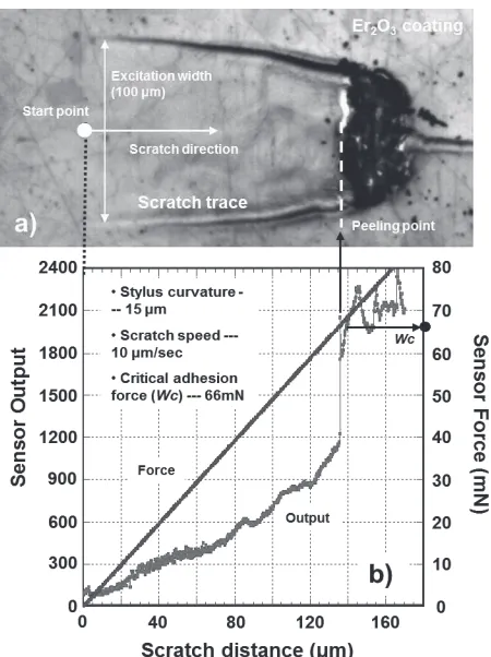
Typical scratch trace image and test data of Er2O3
coating layer using nano-layer scratch instrument are shown in Figs. 6 (a) and (b). The scratch trace image was taken by CCD camera attached to the nano-layer scratch instrument. We found that the scratch trace corresponded with the displacement diagram between the sensor output and the applied scratch force. The excitation amplitude of the stylus became smaller with the increase in the ap-plied scratch force. At the same time, the sensor output was also increased with the decrease in the excitation am-plitude. Here, the sensor output indicates friction force be-tween the stylus and coating surface. On the other hands, the sensor output was increased with increasing applied scratch force and the significant increase of sensor output coincided with the separation point of the scratch trace. We defined the applied force at the significant increase of sensor output as the critical adhesion force (Wc). In this
Fig. 6 Typical scratch trace image and test data of Er2O3
coat-ing layer uscoat-ing the nano-layer scratch instrument. (a) The CCD image of the nano-scratch trace on the Er2O3
coat-ing layer and (b) the displacement diagram between sen-sor output and force.
way, nano-layer scratch instrument is available to evaluate the adhesion strength of the MOCVD processed Er2O3thin
coating.
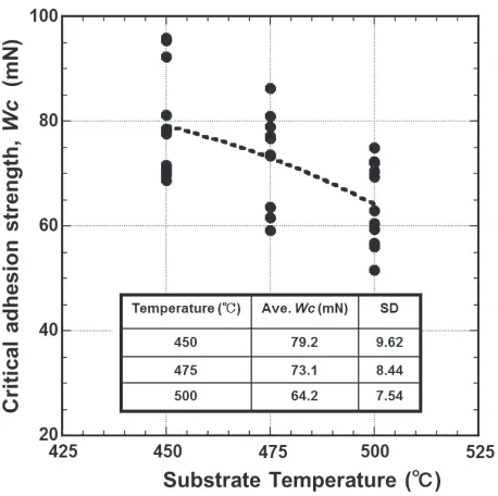
The relationship between formation temperature and the adhesion strength on the MOCVD processed Er2O3
thin coating was investigated. The critical adhesion strength (Wc) as a function of the substrate temperature during synthesis of the Er2O3layer by the MOCVD
pro-cess is shown in Fig. 7. Seven pieces of the coated samples were tested at each temperature. The nano-layer scratch test was carried out at randomly selected three points per one sample, and the adhesion strength was estimated by the average value of the three points. The average adhe-sion strength of Er2O3coating layer changed from 79 mN
to 64 mN with increasing substrate temperature during the MOCVD process. At all substrate temperatures tested, a Er-Cr-O compound layer was observed around interface between the Er2O3coating and the SUS 316 substrate as
Fig. 7 The critical adhesion strength (Wc) as a function of the substrate temperature during the synthesis of Er2O3
coat-ing with MOCVD process.
3.2
The changes of adhesion strength and
microstructure of Er
2O
3coating layer by
the thermal cycling
The critical adhesion strength (Wc) as a function of the number of thermal cycles is shown in Fig. 8. Sim-ilar to Fig. 7, seven coated samples at three points each were tested for a thermal cycling condition. The adhesion strength of Er2O3 coating layer decreased with
increas-ing the number of thermal cycles from 64.1 mN (Original sample) to 51.1 mN (10 times), 44.5 mN (30 times) and 44.2 mN (50 times). It is to be noted that the adhesion strength between 30 and 50 times of thermal cycling are similar to each other. This means that the adhesion strength property was saturated with the number of thermal cycles. On the other hand, the change of texture on the Er2O3
coating was investigated using XRD analysis. XRD pat-terns of the Er2O3 coating layer as a function of
num-ber of thermal cycling are shown in Fig. 9. We found that the Er2O3texture before thermal cycling was oriented
randomly in the coating layer without alignment texture. However, the peak intensity of (400) plane of Er2O3phase
after 50 times of thermal cycling was drastically increased. The peak intensity ratio such as (400)/(222) shown in Fig. 9 was also remarkably increased from 1.52 to 80.62 with 50 thermal cycles. This means that a-axis alignment was pro-moted by the thermal cycling on the Er2O3coating. In
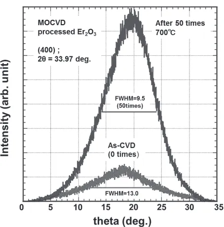
ad-dition, the comparison between the rocking curves of (400) plane on Er2O3 phase (2θ = 33.97 deg.) before and after
the thermal cycling is shown in Fig. 10. The Full Width at Half Maximum (FWHM) value of (400) plane on Er2O3
phase was decreased from 13 to 9.5 by the thermal cycling.
Fig. 8 The critical adhesion strength (Wc) as a function of the number of times of heat-cycling in the Er2O3 coating
layer synthesized with MOCVD process.
Fig. 9 XRD patterns of Er2O3 coating layer synthesized with
MOCVD process before and after the thermal cycling.
This suggests that the crystallinity of Er2O3was improved
by the thermal cycling
Typical TEM image of the cross-sectional area in the interface between the Er2O3coating layer and substrate
Fig. 10 The comparison between the rocking curves of (400) plane on Er2O3phase (2θ=33.97◦) before and after the
thermal cycling.
Fig. 11 TEM image of the cross-sectional area in the interface between Er2O3coating layer and SUS 316 substrate
af-ter 30 thermal cycling.
to about 30∼40 nm. Thicker Er-Cr-O compound layer was formed compared with that before the thermal cycling shown in Fig. 2. These suggested that the Cr diffusion from SUS substrate was promoted by the thermal cycling and the increase of thickness on Er-Cr-O compound layer was caused by the enhanced Cr diffusion.
4. Discussions
In this study, the change of adhesion strength (Wc) of Er2O3 ceramic coating by the thermal cycling was
inves-tigated using nano-scratch method. The change would be-come one of the key factors for applying the coating to ad-vanced breeding blanket system, potentially contributing
between from 30 to 50 times of thermal cycling. Thus, it is suggested that Er2O3coating synthesized with MOCVD
process have significant mechanical durability throughout the blanket life time.
The change of microstructure of Er2O3by the thermal
cycling characterized using XRD analysis, SEM and TEM observations is also discussed. From the comparisons of XRD patterns before and after thermal cycling shown in Fig. 9, we found that lattice parameter of Er2O3crystal
es-timated from XRD peaks was not changed by the thermal cycling. In addition, microstructure of the Er2O3coating
layer was changed from random texture (non-alignment) to a-axis alignment texture. As reported in [13], the peak in-tensity ratio of (400)/(222) plane after 30 times of thermal cycling was obtained to 7.2. Thus, a-axis alignment was promoted by thermal cycling. Generally, FWHM value es-timated by the rocking curve shown in Fig. 10 indicates the degree of crystallintiy, and FWHM after the thermal cycling was decreased compared with that of as-MOCVD sample. This implies that the crystallinity of Er2O3 was
improved by thermal cycling. These suggested that Er2O3
phase was maintained without the phase transformation during the thermal cycling and a-axis grain growth with enhanced Er2O3crystallinity was promoted by the thermal
cycling. From the comparisons of microstructure around the interface of the coating and substrate by the thermal cycling shown in Fig. 11, we found that the Er-Cr-O com-pound layer thickness was increased from 20µm to 40µm after the thermal cycling. This was caused by the Cr diff u-sion from SUS substrate promoted by the thermal cycling. Effective factors to causeWcdegradation by the ther-mal cycling is considered. Generally, the change of mi-crostructure and the residual stress around the interface of coating and substrate are relatively effective factors of coating separation from substrate. In our study, we con-firmed that in some cases perpendicular cracks between Er2O3 columnar crystals were formed after thermal
cy-cling. This will be caused by the different coefficient of thermal expansion. The average coefficient of thermal ex-pansion of SUS 316 (18.5×10⁻⁶◦C−1) was about 2.5 times
larger compared with that of Er2O3(7.25×10⁻⁶◦C−1). The
formation of perpendicular crack will also become one of the factors to causeWcdegradation by thermal cycling.
residual stress around interface between coating and sub-strate by the thermal cycling is estimated by the equation based on the thermal stress as [23],
S =Ef(αf−αs)ΔT d, (2)
whereS is residual stress around interface,Ef is Young’s
modulus of coating,αf andαs are the coefficient of
ther-mal expansion of coating and substrate,ΔT is the change of the temperature on the thermal cycling andd is coat-ing thickness, respectively. Accordcoat-ing to the Eq. (2), the residual stress is the proportional to the coating thickness. Increase of Er-Cr-O compound layer thickness shown in Fig. 11 would cause an increase of residual stress around the interface between coating and substrate. The interfa-cial fracture as a result of the increased stress between Er-Cr-O layer and substrate will be the origin of the coating separation from the substrate.
In addition, the enhancement of a-axis alignment by the thermal cycling shown in Fig. 9 is investigated. Adel A. Sharif et al reported that Young’s modulus of Er2O3
single crystal is 150 and 183 GPa in (100) and (111) plane, respectively [24]. Thus, according to Eq. (1), the residual stress is considered to decrease by the enhancement of a-axis alignment. Therefore, we thought that the formation of the perpendicular cracks and increase of Er-Cr-O layer thickness will be mainly effective reasons to cause theWc
degradation by the thermal cycling. Furthermore, the en-hancement of Er2O3cystallization by the high thermal
cy-cling shown in Fig. 10 promotes change from diversely ori-ented small phases to a homogeneous Er2O3crystal which
is thought to results in the decreased error bar shown in Fig. 9.
The expandability of nano-scratch test in mechanical property evaluation of ceramic coating as the advanced blanket component is examined. In the scratch test, the surface of the coating layer is scratched by a vibrating di-amond stylus of a given curvature radius mounted on an elastic arm while the stylus is being lowered in the coating thickness direction. The coating layer was ground by vi-brating diamond with increasing dynamic load during the scratch test. Then, we propose the scratch test is able to apply to the abrasion evaluation as well. With constant dynamic load applied to the coating with a constant thick-ness, the output of the scratch sensor as a function of time provides abrasion characteristics of the coating. The time at the significant increase of sensor output is defined as the critical abrasion time. It is thought that the change of abra-sion property can be extracted using the scratch time as the parameter.
5. Conclusions
We investigated adhesion strength of Er2O3 coating
using nano-scratch instrument for application to advanced breeding blanket components. The adhesion strength of Er2O3 coating layer could be evaluated with
reproducibil-ity by nano-scratch method.
The adhesion strength of Er2O3 coating layer
de-creased with the increase in the thermal cycling and the adhesion strength degradation was limited to about 70 % of the original Er2O3coating layer. We found that Er2O3
coating synthesized with MOCVD process have signifi-cant mechanical durability and would survive the expected thermal cycling during the life-time of blanket systems. From the comparisons of microstructure and residual stress based on the thermal stress after the thermal cycling, the formation of the perpendicular cracks and increase of Er-Cr-O layer thickness around interface will be the main ef-fective reasons to cause the adhesion strength degradation by the thermal cycling.
Acknowledgments
This work was mainly supported by the Fusion En-gineering Research Project in NIFS (UFFF026), and in part by the NIFS Collaboration Research Program (KEMF045).
[1] S. Malang, H.U. Borgstedt, E.H. Farnum, K. Natesan and I.V. Vitkovski, Fusion Eng. Des.27, 570 (1995).
[2] T. Muroga, T. Tanaka and A. Sagara, Fusion Eng. Des.81, 1203 (2006).
[3] D.L. Smith, K. Natesan, J.-H. Park, C.B. Reed and R.F. Mattas, Fusion Eng. Des.51–52, 185 (2000).
[4] T. Tanaka, Y. Hirooka and S. Fukada, J. Plasma Fusion Res. 89, 384 (2013) (in Japanese).
[5] D.L. Smith, J. Konys, T. Muroga and V. Evtikhin, J. Nucl. Mater.307–311, 1314 (2002).
[6] B.A. Pint, P.F. Tortorelli, A. Jankowski, J. Hayes, T. Muroga, A. Suzuki, O.I. Yeliseyeva and V.M. Chernov, J. Nucl. Mater.329–333, 119 (2004).
[7] A. Sawada, A. Suzuki, H. Maier, F. Koch, T. Terai and T. Muroga, Fusion Eng. Des.75–79, 737 (2005).
[8] X. Li, P. Wu, H. Qiu, S. Chen and B. Song, Thin Solid Film 520, 2316 (2012).
[9] D. Zhang, M. Kondo, T. Tanaka, T. Muroga and T. Valen-tyn, Fusion. Eng. Des.86, 2508 (2011).
[10] Y. Hishinuma, T. Tanaka, T. Tanaka, T. Nagasaka, Y. Tasaki, A. Sagara and T. Muroga, Fusion. Eng. Des. 86, 2530 (2011).
[11] Y. Hishinuma, T. Tanaka, T. Tanaka, T. Nagasaka, S. Yoshizawa, Y. Tasaki and T. Muroga, J. Nucl. Mater.417, 1214 (2011).
[12] Y. Hishinuma, T. Tanaka, T. Tanaka, T. Nagasaka, Y. Tasaki, S. Murakami, K. Matsuda, A. Sagara and T. Muroga, Fusion Sci. Technol.60, 1131 (2011).
[13] Y. Hishinuma, S. Murakami, K. Matsuda, T. Tanaka, Y. Tasaki, T. Tanaka, T. Nagasaka, A. Sagara and T. Muroga, Plasma Fusion Res.7, 2405127 (2012).
[14] K. De Bruyn, M. Van Stappen, H. De Deurwaerder, L. Rouxhet and J.P. Celis, Surf. Coat. Technol.163–164, 710 (2003).
[15] Jeong-Gi Jin, Sung-Ki Lee and Young-Ho Kim, Thin Solid Films466, 272 (2004).