Microscopic change in hardened cement paste due to high-speed impact
Yuya Sakaia*, Ivwananji Sikombeb, Keiko Watanabec and Hiroyuki Inoued
a Institute of Industrial Science, The University of Tokyo, 4-6-1 Komaba, Meguro, Tokyo 153-8505, Japan, ysakai@iis.u-tokyo.ac.jp
b Institute of Industrial Science, The University of Tokyo, 4-6-1 Komaba, Meguro, Tokyo 153-8505, Japan, sikotech@iis.u-tokyo.ac.jp
c College of Science and Engineering, Ritsumeikan University, 1-1-1 Noji-higashi, Kusatsu, Shiga 525-8577, Japan, keikow@fc.ritsumei.ac.jp
d Institute of Industrial Science, The University of Tokyo, 4-6-1 Komaba, Meguro, Tokyo 153-8505, Japan, inoue@iis.u-tokyo.ac.jp
*Corresponding author
Abstract
Impact load was applied to hardened cement paste (HCP) specimens using a gas gun to investigate microscopic changes in the specimens and develop a better response model of concrete subjected to impact load. Plasma emission was observed at the moment of impact at 420 m/s and the colour of the portion near the impact point turned brighter. This brighter portion was analysed, and it was observed that the pore structure was coarser compared to the other portion; however, the results of thermogravimetry and X-ray diffraction analysis were similar. A possible reason is that the generated heat was instantaneous and the rate of the temperature increase in the HCP decreased due to evaporation of water in the HCP. These results indicate that during impact at a few hundred m/s, porosity increase due to heat effect is more dominant than porosity decrease due to mechanical compaction.
Keywords: Cement paste, Impact test, Pore structure, Thermograveimetry analysis, X-ray differential analysis
1. Introduction
Concrete is used in a variety of structures and thus, subjected to a wide range of loads and impact loading. Relatively low-speed impacts often occur due to collisions from vehicles and rocks [1-3]. Middle speed impacts also occur due to hurricanes and explosions produced by flying objects [4-6], while high speed impacts occur due to gunshots and missiles [7-9]. Moon exploration has attracted increasing interest [10] and concrete is one of the promising material for the construction of a lunar base [11,12]. Since there is no atmosphere on the moon, space debris reaches the moon surface and
the velocity of space debris can be ten times faster than that of a bullet [13, 14]; therefore, concrete may be subjected to very high-speed impact in the near future. Various types of experiments have been conducted, from low-speed impact to very-high speed impact, to investigate the fracture patterns of concrete subjected to impact load, and results have shown that concrete exhibits various fracture patterns and responses depending on the property and velocity of the projectile as well as the concrete strength. Kennedy [7] classified the fracture patterns of concrete into the following seven categories: (a) penetration, (b) cone cracking and plugging, (c) spalling, (d) radial cracking associated with (i) the proximal face and (ii) the distal face, (e) scabbing, (f) perforation, and (g) overall structural responses and failures. Li et al. [15] summarized various models applied to calculate the response of concrete subjected to impact loading. It is clear from the above review papers that macroscopic damage occurs in concrete due to impact load. However, microscopic damage or property change due to impact load has not been thoroughly investigated.
The stress condition induced by impact load can be simulated by the triaxial test. Gran and Frew [16] conducted an impact test using a rocket bomb of 2.3 kg flying at 315 m/s, which induced triaxial stress greater than 150 MPa in the concrete. After their experiment, a triaxial test was conducted at a confining pressure of up to 400 MPa to investigate the response of concrete subjected to impact load, and the stress–strain curves [17] and the effects of aggregates [18,19], moisture content [20], and so forth were reported. Sakai et al. [21] conducted a triaxial test on hardened cement paste (HCP) and reported that the porosity of HCP decreased after the test. In the numerical simulation of impact test using concrete, reduction in the porosity is considered an important parameter for accurate simulation [22,23]. However, it has not been experimentally determined whether the property change of HCP due to impact load can be reproduced by the triaxial test. This should be clarified before conducting a triaxial test to simulate the response of concrete subjected to impact.
Ren et al. [24] carried out scanning electron microscope (SEM) observation and X-Ray diffraction (XRD) analysis on ultra-high performance concrete after impact by a projectile of approximately 14 g flying at 914 m/s. They reported a high-pressure and high-temperature phase of silica and pointed out that the high temperature was generated due to the impact; however, their study focused on the bonding between fiber and cement paste matrix. The authors recommended that to produce concrete with high resistance against impact, a material that does not undergo crystalline transformation should be used. They also highlighted the possibility that water in concrete evaporated due to heat generated by the impact and the vapor induced damage to the concrete. As a result, the authors also recommended the use of materials that melt easily to prepare an escape route for the vapor. It is well-known that an impact generates heat [25,26]; therefore, the phase and pore structure of HCP may change and it is inappropriate to conduct a triaxial test to simulate the response of concrete due to impact load without considering the effect of heat.
and to determine whether the same change observed in HCP in the triaxial test occurs in the impact test. To investigate the change in cement paste due to impact load, the test should be conducted using HCP and not concrete because it is difficult to separate the change in the cement paste and that in the aggregate. Therefore, understanding microscopic changes in HCP due to impact load will be helpful in developing a more realistic concrete simulation model.
2.Experimental Method 2.1 Specimen
This study used HCP with water to cement ratio of 0.4. Table 1 and 2 present the properties of ordinary Portland cement. The paste was first mixed for 30 s at low speed (orbital rotation: 62 ± 5 rpm, planetary rotation: 140 ± 5 rpm). The mixer was stopped for 30 s to 60 s to scrap off cement paste on the mixing bowl and paddle. The mixer was then set to high speed (orbital rotation: 125 ± 5 rpm, planetary rotation: 284 ± 5 rpm) and allowed to run for 60 s. The mixed paste was cast into φ100 × 100 mm cylindrical moulds and sealed. The HCP was demoulded 24 h after casting, kept under water at 20 °C for 8 months, and sealed in plastic bags until testing.
2.2 Impact test procedure
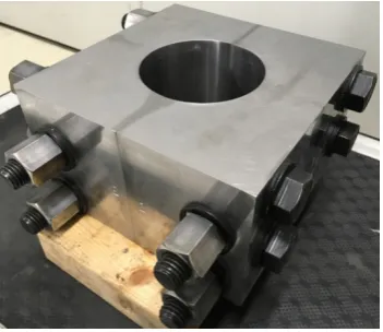
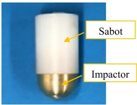
A vertical single-stage diaphragmless gas gun was used for the impact test. In an ordinary gas gun, a projectile is launched by the breaking of a diaphragm due to gas pressure, and the fragments of the diaphragm fly and hit the target [27,28]. The gun used in this study does not employ a diaphragm, therefore, the effect of flying pieces of the diaphragm is eliminated. The outlook of the gun is shown in Fig. 1. The projectile was launched from a pressure vessel through a launch tube and impacted the specimen in a test chamber. The specimen was confined with a set of steel molds, which can be separated into four pieces as shown in Fig. 2. The confinement was prepared to reduce scattering of the specimen pieces due to the impact so that the sample used for the analysis can be collected. The projectile is shown in Fig. 3; the impactor is a hemispherical copper with a radius of 5 mm, while the sabot is made of polyethylene. The mass of the projectile was 16 g including a neodymium magnet inside it. The magnet induces electromotive force when it passes through some coils placed at the exit
Table 1 Chemical property of cement.
Ig. Loss Insol. SiO2 Al2O3 Fe2O3 CaO MgO SO3 Na2O K2O 2.64 0.06 20.27 5.30 2.95 64.8 0.95 1.74 0.28 0.45
Table 2 Physical property of cement. Density Specific surface area
g/cm3 cm2/g
of the launch tube to determine the velocity of the projectile from the time lag of the electromotive force. The collision was recorded using a high-speed camera (Phantom v711, Vision Research Inc., NJ, USA). The projectiles were launched four times; the velocity of two of the projectiles was 200 m/s, while that of the other projectiles was 420 m/s.
Fig. 1. Diaphragmless vertical gas gun. Launch tube
Test chamber Pressure
2.3 Observation with optical microscope and scanning electron microscopy
The non-tested specimen and pieces of the tested specimens were impregnated with a two-component epoxy resin (room-temperature curing). Then, a thin section with thickness of 30 μm was prepared from the tested specimen and observed using a polarization microscope (ECLIPSE LV100N POL, Nikon, Tokyo, Japan).
For SEM observation, 2 × 2 × 0.3 mm samples were cut from the specimens. Alumina powder was used to polish the sample surface. The sample was first polished for 10 min using ethanol and coarse alumina powder (400 grit) on a glass plate. Thereafter, the specimen was immersed in ethanol, and washed in an ultrasonic bath for 5 min. This procedure was repeated using fine powder (1200 grit) to smoothen the sample surface. The sample was dried for 24 h at 40 °C and 20% relative humidity and the D-dry method [29] was applied for 24 h. After drying, the sample was polished using a cross-section polisher (SM-090010, JEOL Ltd., Tokyo, Japan), the sample surface was coated with carbon, and back scattered electron images were observed using SEM (JSM-7000F, JEOL Ltd., Tokyo, Japan).
2.4 Mercury intrusion porosimetry (MIP)
The pore size distribution of the samples was analyzed using MIP (POREMASTER 60GT, Quantachrome, Florida, USA). The tested and non-tested specimens were crushed into cubes with edges measuring 5 mm and these were immersed in acetone for 24 h. Subsequently, the cubes were dried using the D-dry method [29] for 24 h and 1 g of the cubes was used for MIP analysis.
2.5 Thermal gravimetric (TG) analysis and X-Ray diffraction analysis
TG analysis was carried out using TG-DTA (EXSTAR 6000, Seiko Instruments) to analyze the thermal property of the HCP. Pieces of the samples were taken from the tested and non-tested specimens, crushed into powder, and sieved using a 150-μm sieve. Approximately 10 mg of each sample was collected, and TG analysis was carried out. The sample was heated up to 1000 °C at the rate of 20 °C/min in nitrogen atmosphere.
XRD analysis was carried out to investigate the change in the crystalline phase due to the impact. Fig. 3. Projectile.
Multiflex (Rigaku, Tokyo, Japan) was used at the output of 40 kV and 30 mA. The powder sample for XRD analysis was prepared using the same procedure used for TG analysis. Since the amount of the sample was small, a zero diffraction sample holder was used.
2.6 Preheating with laser pulse and electric furnace
Luminescence due to plasma was observed at the impact of the projectile into the HCP, which will be explained in section 3.1. To investigate the effect of instantaneous heating on the HCP, a non-tested specimen of 50 × 50 × 10 mm was heated using laser pulse. Another specimen was heated in an electric furnace at 300 °C for 2 h for comparison with the laser heated specimen.
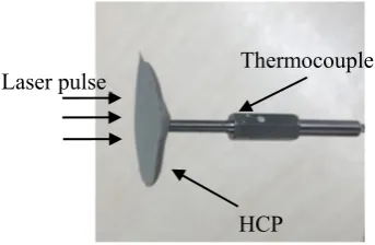
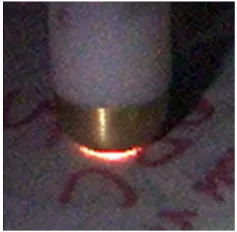
Laser heating was carried out using a YAG laser. The output was 5.9 W, while the width and interval of the pulse were 100 ns and 0.1 s, respectively. The color of the portion near the impact point turned brighter and laser pulse was repeatedly applied to HCP for 5 s until a similar color change was observed; this will be described in 3.1. The cutting surface of the color change portion is shown in Fig. 4. The color change occurred up to a depth of 3 mm from the surface at the center of the heating. To measure the temperature increase due to laser heating, a type-K thermocouple (Medtherm, Alabama, USA) was embedded into the cement paste plate at a depth of 5 mm (Fig. 5). Laser pulse was applied to the cement paste surface at the tip of the thermocouple and the temperature was measured at intervals of 5 μs. The measured temperature was up to 60 °C after laser heating for 5 s. During heating, vapor was generated from the heating point. The portion where a color change occurred was extracted and this portion was used for the analysis described above.
Fig. 4. Color change due to laser heating. Color change
Fig. 5. Set up for temperature measurement. Thermocouple
3. Results and discussion 3.1 High-speed impact test
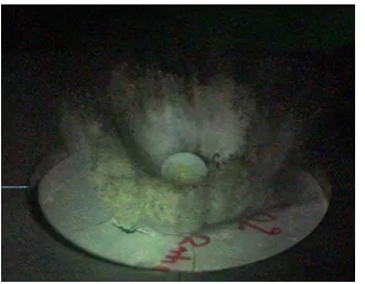
Fig. 6 shows the moment of the scatter of HCP surface due to the impact of a projectile travelling at 420 m/s. The colour of the portion near the impact point turned brighter (Fig. 7). A similar colour change was observed for the impact at 250 m/s. The cutting surface of the specimen, which was cut after the impact test and impregnated with a two-component epoxy resin, is shown in Fig. 8. The portion of the 22 mm depth was scattered. The dark lines in the image are cracks filled with the intruded epoxy resin. The crack density was higher near the impact point. There is a darker portion near the impact point and this region was brighter as shown in Fig. 7; however, it turned darker because more epoxy resin intruded into the tiny cracks of this area. Fig. 9(a) shows a piece of the tested sample. The brighter portion shown in the figure has a complicated shape. Fig. 9(b) shows the image of the polarization microscope and the interface of the brighter and darker portions is curved. It is unlikely that mechanical stress induced such a complicated and curved interface; therefore, another factor may have caused the colour change in HCP during impact.
Fig. 6. Projectile hitting the sample. Fig. 7. Sample after the impact. Color change
Fig. 10 shows the moment of the impact recorded at a frame rate of 270,000/s and luminescence of plasma was observed at the impact point. The generation of plasma has been observed in the impact test of other materials [30,31]; however, to the best of the authors knowledge, this is the first time it is observed in cementitious material. Plasma is a state where an atom is ionized and decomposed into a cation and electron. Since plasma was observed in one frame and recording was done at an interval of 3.7 μs, plasma was emitted for a maximum of approximately 7 μs. In the following sections, the samples taken from a non-tested specimen and the brighter portion of the tested sample were analysed and compared. The results of the analysis on the samples heated using laser pulse and electric oven will also be presented for comparison.
3.2 SEM observation
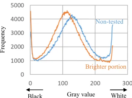
According to the backscattered electron images shown in Fig. 11, the brighter sample taken from the tested sample appears darker compared to the non-tested sample. A grey-scale histogram of these images was prepared using an image processing software (Image J, National Institutes of Health, MD, USA) to carry out a quantitative comparison. The histogram shows the frequency of each colour, assuming that the image is composed of 256 colours (Fig. 12). Gray values of 0 and 255 correspond
Fig. 9. Cut piece of sample after test.
(a)Thin section (b)Polarization microscope (crossed nicols)
10mm 1mm
Brighter part Brighter part
to black and white, respectively. The histogram of the sample taken from the brighter portion of the tested sample shifted to the left, and the gray value decreased indicating that the image turned darker. A similar change was observed in HCP after the triaxial test with high-confining pressure [21]. The contrast of the back scattered image changes depending on the atomic number and the molecular structure such as crystalline nature [32]. A possible reason is that structural change occurred at the molecular level.
3.3 Pore size distribution
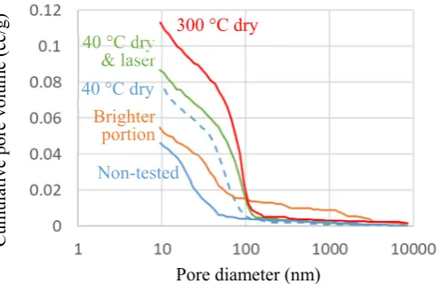
The pore size distribution measured using MIP is shown in Fig. 13. Compared to the non-tested sample, the brighter portion taken from the tested sample had a larger pore size and volume. It has been reported that the portion near the impact point is subjected to compressive stress [22,23]. Forquin et
Fig. 11. Backscattered electron images.
(a) Non-tested sample (b) Sample taken from brighter portion
Fig. 12. Histogram of gray value of images in Fig. 11.
Freque
ncy
Gray value
Non-tested
Brighter portion
al. [33] reported a decrease in the air volume of mortar due to impact load. HCP also showed a smaller pore size and volume after the triaxial test [21]. Therefore, a similar phenomenon was expected after the impact test; however, the result obtained was different. This indicates that the effect of triaxial stress on cement paste matrix was not dominant during the impact test. Since plasma was observed at the impact, it is possible that the high temperature changed the pore size distribution.
However, as introduced in section 2.6, although the laser pulse can induce high temperature and is used for metal welding [34,35], the temperature at which the surface of the HCP turned brighter during laser heating was 60 °C possibly due to the suppression of the temperature increase by the evaporation of free water. MIP could not be carried out on the laser-heated sample because the depth of the colour changed portion was small and an appropriately sized sample for MIP was not obtained. This difference in the colour change area may be attributable to the difference in the amount and duration of the induced heat. Thus, the sample was preheated at 40 °C, then laser heating was applied for 5 s. Fig. 13 shows that the pore volume of the smaller pore significantly increased even at low preheating at 40 °C. A similar change was also reported in a previous study [36]. Laser heating after preheating at 40 °C further increased the porosity. In these samples, the pore was not as large as the brighter portion possibly because the volume increase of the larger pore could be due to the vapor pressure generated at the instantaneous evaporation of free water during impact.
3.4 TG and XRD analysis
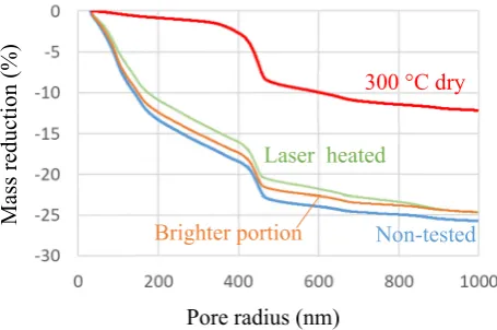
The result of the thermogravimetry is shown in Fig. 14 and only a slight difference occurred between the non-tested sample and the tested sample. This result indicates that the thermal effect due to the impact did not affect the chemical properties of HCP. The result of the sample preheated at 300 °C is also shown in Fig. 14; a small mass decrease occurred up to 300 °C and then the curve became almost
Cumu
lat
ive
p
ore v
ol
ume (c
c/g)
Non-tested
Brighter portion
Fig. 13. Pore size distribution. Pore diameter (nm) 40 °C dry
40 °C dry & laser
parallel with the non-tested sample. This is because the mass reduction that occurred up to 300 °C was during preheating. The curve of the tested sample is parallel with that of the non-tested sample at temperatures higher than 150 °C indicating that the maximum temperature that the sample experienced in the impact was 150 °C. However, unlike the sample preheated at 300 °C, the tested sample yielded a large mass reduction even when the temperature was below 150 °C. A possible reason is that the temperature increase due to the impact was instantaneous owing to cooling resulting from water evaporation. The curve of the laser heated sample is similar to that of the non-tested sample at temperatures higher than 100 °C; therefore, the maximum temperature the sample experienced during laser-heating was likely approximately 100 °C. The maximum temperature indicated in section 2.6 was lower (60 °C) probably because the tip of the thermocouple was not at the surface but slightly inside, while the sample for the thermogravimetry analysis was collected from the surface. Ren et al. [24] reported that a high-temperature and high-pressure phase of SiO2 was generated. This is probably because the speed of their projectile was faster (914 m/s) than the speed used in our study, the projectile collided with the gravel, and suppression of the rate of the temperature increase due to water evaporation was small.
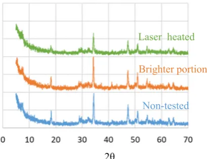
The result of the XRD analysis is shown in Fig. 15 and there is no significant difference between the samples. This result indicates that a change in the molecular structure did not occur during impact and laser heating.
Fig. 14. Result of thermogravimetric analysis. Pore radius (nm)
Mass reduction (%)
Non-tested
Brighter portion
Laser heated
3.5 Discussion on change in HCP due to impact
The obtained results indicate that the impact resulted in plasma emission and the surface of HCP was subjected to high temperature. However, TG and XRD analyses did not yield any change; however, the pore volume and size increased. This is probably because the instantaneous heat did not increase the temperature in HCP due to evaporation of water. The pore structure change was likely due to drying by evaporation. The pore volume and size are known to increase with drying [36, 37]. The colour of the portion near the impact point turned brighter and this change is likely due to the drying.
In this study, HCP subjected to a projectile at 420 m/s was analysed. However, a similar colour change due to impact on the specimen was also observed in the specimen subjected to a projectile at 250 m/s. This indicates that heat was generated, and the sample was dried even at this velocity. In the case of concrete, the rate of the temperature rise in the aggregate due to the impact can be higher than in the cement paste matrix due to the absence of water, which decreases the temperature rise. The reduction in the rate of the temperature rise due to evaporation possibly depends on the moisture content of the cement paste and a reduction was observed in this study because the specimen was cured under water and kept sealed until testing. As the impact speed decreases, the heat generated by the impact likely decreased and the pore volume and size in the cement paste could be reduced by the triaxial stress, as reported in a previous study [21]. The increase or decrease in the pore size and volume due to impact probably depends on the balance between the mechanical effect and heat effect. To understand the response of concrete subjected to impact load and to simulate the response with high accuracy, the condition of the increase and decrease in the pore size and volume should be investigated.
4. Conclusions
Researchers have conducted impact tests on concrete specimens. However, the results obtained from analysis of the specimen include information on cement paste and aggregate, which is difficult to
2θ
Fig. 15. X-ray diffraction analysis. Non-tested
categorize. In this study, HCP was subjected to impact load and analysed. The colour near the impact point turned brighter and the pore structure of this portion was coarse compared to the other portion even though the chemical properties are similar. This is probably because heat is generated due to the impact, but the rate of the temperature rise due to the heat decreased owing to evaporation of water in the HCP. In this study, the impact velocity was in the range of 250–420 m/s; however, a lower impact velocity can decrease the porosity as observed in the sample after the triaxial test. The relationship between the impact velocity and the pore structure should be investigated for the simulation of impact on concrete with high accuracy.
Acknowledgement
This study was financially supported by the Steel Foundation for Environmental Protection Technology. Part of this work was conducted at the Advanced Characterization Nanotechnology Platform of the University of Tokyo, supported by the "Nanotechnology Platform" of the Ministry of Education, Culture, Sports, Science and Technology (MEXT), Japan.
References
[1] H.-H. Tsang, N. Lam, Collapse of reinforced concrete column by vehicle impact, Comput-Aided Civ. Inf. 23 (2008) 427-436.
[2] L. Prochowski, Analysis of displacement of a concrete barrier on impact of a vehicle: theoretical model and experimental validation, J. KONES 17 (2010) 399-406.
[3] S.L. Nicot, Rockfall Engineering, John Wiley & Sons, 2013.
[4] J.E. Minor, Windborne debris and the building envelope, J. Wind Eng. Ind. Aerodyn. 53 (1994) 207-227.
[5] N. Lin, J.D. Holmes, C.W. Letchford, Trajectories of wind-borne debris in horizontal winds and applications to impact testing, J. Struct. Eng. 133 (2007) 274-282.
[6] P.S. Pulson, Structures Under Shock & Impact III, WIT Press, 1994.
[7] R.P. Kennedy, A review of procedures for the analysis and design of concrete structures to resist missile impact effects, Nucl. Eng. Des. 37 (1976) 183-203.
[8] F. Vossoughi, C.P. Ostertag, P.J.M. Monteiro, G.C. Johnson, Resistance of concrete protected by fabric to projectile impact, Cem. Concr. Res. 37 (2007) 96-106.
[9] J.T. Gomez, A. Shukla, Multiple impact penetration of semi-infinite concrete, Int. J. Impact Eng. 25 (2001) 965-979.
[10] E. Gent, Moon bases being planned now may show us how to live off-planet, 2018. https://www.nbcnews.com/mach/science/moon-bases-being-planned-now-may-show-us-how-live-ncna855826 (accessed June 20th 2018).
313-325.
[12] T. D. Lin, J.A. Senseney, L.D. Arp, C. Lindbergh, Concrete lunar base investigation, J. Aerospace Eng. 2) (1989) 10-19.
[13] R. Roybal, P. Tlomak, C. Stein, H. Stokes, Simulated space debris impact experiments on toughened laminated thin solar cell cover glass, Int. J. Impact Eng. 23 (1999) 811-821.
[14] H. Klinkrad, Space Debris: Models and Risk Analysis, Springer Science & Business Media, 2006.
[15] Q.M. Li, S.R. Reid, H.M. Wen, A.R. Telford, Local impact effects of hard missiles on concrete targets, Int. J. Impact Eng. 32 (2005) 224-284.
[16] J.K. Gran, D.J. Frew, In-target radial stress measurements from penetration experiments into concrete by ogive-nose steel projectiles, Int. J. Impact Eng. 19 (1997) 715-726.
[17] Y. Malecot, L. Daudeville, F. Dupray, C. Poinard, E. Buzaud, Strength and damage of concrete under high triaxial loading, Eur. J. Environ. Civ. Eng. 14 (2010) 777-803.
[18] X.H. Vu, L. Daudeville, Y. Malecot, Effect of coarse aggregate size and cement paste volume on concrete behavior under high triaxial compression loading, Constr. Build. Mater. 25 (2011) 3941-3949.
[19] C. Poinard, E. Piotrowska, Y. Malecot, L. Daudeville, E.N. Landis, Compression triaxial behavior of concrete: the role of the mesostructure by analysis of X-ray tomographic images, Eur. J. Environ. Civ. Eng. 16 (2012) s115-s136.
[20] X.H. Vu, Y. Malecot, L. Daudeville, E. Buzaud, Experimental analysis of concrete behavior under high confinement: Effect of the saturation ratio, Int. J. Solids Struct. 46 (2009) 1105-1120. [21] Y. Sakai, M. Nakatani, A. Takeuchi, Y. Omorai, T. Kishi, Mechanical behavior of cement paste and alterations of hydrates under high-pressure triaxial testing, J. Adv. Concr. Technol. 14 (2016) 1-12.
[22] N. Burlion, F. Gatuingt, G. Pijaudier-Cabot, L. Daudeville, Compaction and tensile damage in concrete: constitutive modelling and application to dynamics, Comput. Methods Appl. Mech. Eng. 183 (2000) 291-308.
[23] W. Shiu, F.-V. Donze, L. Daudeville, Compaction process in concrete during missile impact: a DEM analysis, Comput. Concr. 5 (2008) 329-342.
[24] F. Ren, C.H. Mattus, J.J.-A. Wang, B.P. DiPaolo, Effect of projectile impact and penetration on the phase composition and microstructure of high performance concretes, Cem. Concr. Comp. 41 (2013) 1-8.
[25] C.L. Rao, V. Narayanamurthy, K. Simha, Applied Impact Mechanics, John Wiley & Sons, 2016.
[27] M. Wegener, M. Sutcliffe, R. Morgan, Optical study of a light diaphragm rupture process in an expansion tube, Shock Waves 10 (2000) 167-178.
[28] K. Togami, T. Hashimoto, K. Takayama, Hypervelocity flow research in ballistic range, 24th International congresss of aeronautical sciences, Yokohama, Japan, 2004.
[29] J. Zhang, G.W. Scherer, Comparison of methods for arresting hydration of cement, Cem. Concr. Res. 41 (2011) 1024-1036.
[30] W. Song, Y. Lv, J. Li, C. Wang, J. Ning, Influence of impact conditions on plasma generation during hypervelocity impact by aluminum projectile, Phys. Plasmas 23 (2016) 073506.
[31] A. Fletcher, S. Close, D. Mathias, Simulating plasma production from hypervelocity impacts, Phys. Plasmas 22 (2015) 093504.
[32] K.D. Vernon-Parry, Scanning electron microscopy: an introduction, III-Vs Review 13 (2000) 40-44.
[33] P. Forquin, A. Arias, R. Zaera, Role of porosity in controlling the mechanical and impact behaviours of cement-based materials, Int. J. Impact Eng. 35 (2008) 133-146.
[34] L.K. Pan, C.C. Wang, Y.C. Hsiao, K.C. Ho, Optimization of Nd: YAG laser welding onto magnesium alloy via Taguchi analysis, Opt. Laser Technol. 37 (2005) 33-42.
[35] F.M. Ghaini, M.J. Hamedi, M.J. Torkamany, J. Sabbaghzadeh, Weld metal microstructural characteristics in pulsed Nd: YAG laser welding, Scripta Mater. 56 (2007) 955-958.
[36] Y. Suda, I. Kono, T. Saito, T. Saeki, Evaluation for air mass trasport of hardend cement paste drying various humidity by pore structure and hydration product, Cem. Sci. Concr. Technol. 71 (2017) 210-217.