Atmos. Meas. Tech., 10, 1999–2007, 2017 https://doi.org/10.5194/amt-10-1999-2017 © Author(s) 2017. This work is distributed under the Creative Commons Attribution 3.0 License.
Dry particle generation with a 3-D printed fluidized bed generator
Michael Roesch1, Carolin Roesch1, and Daniel J. Cziczo1,2
1Department of Earth, Atmospheric and Planetary Sciences, Massachusetts Institute of Technology, Cambridge, 02139, USA 2Department of Civil Environmental Engineering, Massachusetts Institute of Technology, Cambridge, 02139, USA
Correspondence to:Michael Roesch ([email protected])
Received: 2 December 2016 – Discussion started: 17 January 2017 Revised: 28 April 2017 – Accepted: 2 May 2017 – Published: 2 June 2017
Abstract.Here we describe the design and testing of PRIZE (PRinted fluidIZed bed gEnerator), a compact fluidized bed aerosol generator manufactured using stereolithography (SLA) printing. Dispersing small quantities of powdered ma-terials – due to either rarity or expense – is challenging due to a lack of small, low-cost dry aerosol generators. With this as motivation, we designed and built a generator that uses a mineral dust or other dry powder sample mixed with bronze beads that sit atop a porous screen. A particle-free airflow is introduced, dispersing the sample as airborne particles. Total particle number concentrations and size distributions were measured during different stages of the assembling process to show that the SLA 3-D printed generator did not gener-ate particles until the mineral dust sample was introduced. Time-series measurements with Arizona Test Dust (ATD) showed stable total particle number concentrations of 10– 150 cm−3, depending on the sample mass, from the sub- to super-micrometer size range. Additional tests with collected soil dust samples are also presented. PRIZE is simple to as-semble, easy to clean, inexpensive and deployable for labo-ratory and field studies that require dry particle generation.
1 Introduction
Investigating dry powder samples, such as mineral and soil dust and volcanic ash, is essential to understand their atmo-spheric influence, especially on clouds (Boucher et al., 2013). Inexpensive commercial nebulizers have often been used to aerosolize these types of samples but require them first to be made into a water slurry. Sullivan et al. (2010), Kumar et al. (2011), Garimella et al. (2014) and Tang et al. (2016) demonstrated that such aqueous processing alters the surface composition, physiochemical properties and hygroscopicity
of the particles even after condensed-phase water is com-pletely removed. Samples therefore often need to be dis-persed by particle generators that do not change these charac-teristics. Different types of generators, such as rotating brush generators (Cziczo et al., 2013; Hiranuma et al., 2015), flu-idized bed generators (FBGs) (Tobo et al., 2012; Hartmann et al., 2016) and shakers (Garimella et al., 2014), have been used for dry dispersion depending on the amount of material and the experimental setup. In some applications only a small number of particles is needed, or for a short period of time. These include some filter sampling (Ardon-Dryer and Levin, 2014), electrodynamic and other particle trapping (Hesse et al., 2002) and single particle mass spectrometry (Murphy, 2006). Moreover, the sample to be aerosolized might be lim-ited due to rarity or expense, necessitating a generation sys-tem capable of working with gram-level quantities. These uses motivate a small, low-cost and easy-to-set-up dry par-ticle generator.
2000 M. Roesch et al.: Dry particle generation with a 3-D printed fluidized bed generator
Figure 1.Dimensioned drawings of PRIZE:(a)rear view;(b)side
view;(c)top view. All dimensions are in millimeters. The
genera-tor body consists of seven components: (1) inlet, (2) internal cone, (3) radial grid with openings, (4) elutriator tube, (5) mounting holes, (6) LED mount and (7) rotameter (or other flow meter) mount.
dispersed is often charged due to triboelectrification. This is caused by friction between the generator walls, the beads and the particles themselves (Mehrani et al., 2007). Using con-ductive wall material or ionization through radioactive neu-tralizers can decrease this effect (Boucher and Lua, 1982; Forsyth et al., 1998). An alternative means of particle pro-duction is agitation of dry materials (Sullivan et al., 2009). Examples include flasks in combination with ultrasonic baths or mechanical shakers. In both cases, mechanical or other ag-itation devices need to be combined with sample containers and flow hardware for aerosolization of samples.
The objective of this study was to produce a small, low-cost 3-D printed FBGs able to disperse small quantities of dry micrometer-sized samples without artifact particles from either the generator or bed. In comparison to existing disper-sion devices, the PRIZE (PRinted fluidIZed bed gEnerator) does not contain moving parts, features smaller dimensions and mass and has a lower cost, requiring only access to 3-D printing. This allows for multiple PRIZEs to be used with different samples, thereby reducing the time and possible ar-tifacts associated with cleaning procedures on a single gen-erator. 25 33.40 1 10 15 6.35 4.35 (a) (b)
2
1
A
B
2
1
B
A
WEIGHT: FluidizedBed-Lid-1inchPROPRIETARY AND CONFIDENTIAL
THE INFORMATION CONTAINED IN THIS DRAWING IS THE SOLE PROPERTY OF MASSACHUSETTS INSTITUTE OF TECHNOLOGY (MIT). ANY REPRODUCTION IN PART OR AS A WHOLE WITHOUT THE WRITTEN PERMISSION OF MIT IS PROHIBITED.
COMMENTS:
SHEET 1 OF 1 Q.A. MFG APPR. ENG APPR. CHECKED DRAWN DATE NAME
DIMENSIONS ARE IN MM TOLERANCES: FRACTIONAL ANGULAR: MACH BEND TWO PLACE DECIMAL THREE PLACE DECIMAL
NEXT ASSY USED ON
APPLICATION DO NOT SCALE DRAWING
FINISH MATERIAL
REV.
ADWG. NO. SIZE
SCALE:1:1 Michael Roesch 07/2016
Figure 2.Dimensioned drawing of a single port outlet lid:(a)side
view;(b)top view. All dimensions are in millimeters.
N2 R Filter PRIZE CPC OPS Filter
0.35 Lpm 1.0 Lpm ~2 . 65 L p m 4.0 Lpm
Figure 3.Schematic of the experimental setup used in this study.
A filtered dry nitrogen flow was controlled by a rotameter (R) up-stream of PRIZE. Downup-stream, the flow was split into three parts to a CPC, an OPS and excess flow discarded through a filter.
2 Methods 2.1 Design
PRIZE consists of two main parts, the generator body (Fig. 1) and exchangeable lids with customizable outlet configura-tions (Fig. 2). The instrument, except the porous screen and the bronze beads comprising the bed, was designed using a computer-aided design (CAD) program (Solidworks 2015; Dassault Systems). The PRIZE follows similar designs by Marple et al. (1978). In contrast to the aforementioned gener-ator or the commercially available FBAG and SSPD, PRIZE does not contain any moving parts or a supply chain to feed fresh dry powder into the bed. This feature was chosen to keep the setup simple and reproducible.
M. Roesch et al.: Dry particle generation with a 3-D printed fluidized bed generator 2001
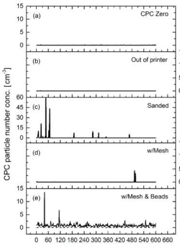
Figure 4.Time-series measurements of particle number
concentra-tions:(a)CPC with filter;(b)freshly printed generator;(c)through
the generator after wet sanding;(d)through the generator after wet
sanding and installing the porous screen;(e)fully assembled
gener-ator including porous screen and bronze beads atop as bed material, without (solid line) and with a stainless steel insert (dashed line).
bronze beads that form the bed. Above the porous screen is a 35 mm long and 25.4 mm diameter elutriator tube; the bronze bead bed is located inside the elutriator. The elutriator tube is topped with a lid with a 6.35 mm (0.25 in.) outlet. We inves-tigate configurations both with and without a stainless steel insert forming the walls of the elutriator. To prevent leakage, lids are equipped with inner side O rings. Based on the num-ber of instruments connected to the generator, lids designed with single or multiple 6.35 mm outlets can be installed (a single outlet lid is shown in Fig. 2). Mounts for a rotameter and a 3 mm light-emitting diode (LED) to illuminate the bed were designed at the left side of the generator body. Mount-ing holes at the bottom were designed to secure the genera-tor to a surface during operation. The overall dimensions of PRIZE are 70 mm×60 mm×98 mm (width, depth, height). All designed parts are saved as style files (.stl) to be readable by the 3-D printer software.
2.2 Manufacturing
The generated construction files were uploaded to the 3-D printer software (PreForm, Formlabs Inc.). In the pro-gram, the parts were oriented on the virtual build platform and scaffolding with 0.5 mm contact points were generated for support during the printing process. The oriented and
Figure 5.Average particle size distributions:(a)OPS with filter;
(b)freshly printed generator; (c)through the generator after wet
sanding;(d)through the generator after wet sanding and installing
the porous screen;(e)fully assembled generator including porous
screen and bronze beads atop as bed material, without (circles) and with a stainless steel insert (triangles).
supported parts were then positioned on the virtual build platform and uploaded to the 3-D stereolithography (SLA) printer (Form 2, Formlabs Inc.). Clear photopolymer resin (FLGPCL02, Formlabs Inc.) was used as the printing mate-rial. This allowed for observation of the particle generation. At the start of the print process the resin was automatically heated to 31◦C and kept at this temperature until the print was finished. The liquid resin is cured through photopoly-merization by a 405 nm violet laser. The resolution of the printed layers can be adjusted to 25, 50 or 100 µm. Using the highest resolution (of 25 µm), printing lasted∼19 h, while using the lowest resolution only ∼7 h were required. The PRIZE used in this study was printed with 100 µm resolution with no significant performance changes observed across this resolution range.
0 1 0 0 2 0 0 3 0 0 4 0 0 5 0 0 6 0 0 0 5 1 0 1 5 2 0 2 5 3 0 CP C pa rti cle nu m be rc on c. [c m -3]
( a )
0 – 6 0 0 s E l a p s e d ti m e [ s ]
6 0 0 7 0 0 8 0 0 9 0 0 1 0 0 0 1 1 0 0 1 2 0 0
0 5 1 0 1 5 2 0 2 5 3 0 CP C pa rti cle nu m be rc on c. [c m -3]
( c )
6 0 0 – 1 2 0 0 s E l a p s e d ti m e [ s ]
0 1 2 3 4 5 6 7 8 9 1 0
0 1 0 2 0 3 0 4 0 5 0 6 0
( b )
O p t i c a l d i a m e t e r [μ m]
0 1 2 3 4 5 6 7 8 9 1 0
0 1 0 2 0 3 0 4 0 5 0 6 0 dN / dl og Dp [c m -3]
O p t i c a l d i a m e t e r [μ m] ( d )
dN / dl og Dp [c m -3]
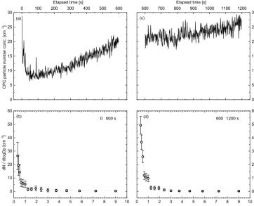
Figure 6.Arizona Test Dust measurements:(a)particle number concentration for the first 600 s;(b)corresponding particle size distribution;
(c)particle number concentration for the second 600 s;(d)corresponding particle size distribution.
time also depends on the size and the wall thickness of the printed part). The printed generator parts were post-cured overnight (∼8 h) in a custom-built UV box. Inside are 300 surface-mount device (SMD) LED emitting at 405 nm, with a total intensity of 934.8 cd. After post-curing, the parts were polished using a Dremel with a soft felt bob.
2.3 Experimental setup
A schematic of the experimental setup with the relevant flow rates used in this study is shown in Fig. 3. Dry filtered ni-trogen was used as the carrier gas. The flow was controlled by a rotameter (MR3A, Omega Engineering). Flow tests with only the 100 µm bronze beads (ACuPowder Interna-tional LLC) showed that 4.0 L min−1 was sufficient to cre-ate a “boiling” motion in the fluidized bed (i.e., the threshold where the gas did not only pass through the pore space of the beads without moving them), visible through the clear resin wall of the elutriator. All measurements in this study were therefore performed at 4.0 L min−1. At the outlet of the generator the flow was split into three pathways. The first was connected to a condensation particle counter to measure particle number concentrations in the size range from 0.007 to 2.0 µm (CPC, BMI Inc.), the second to an optical particle sizer to determine particle number size distributions in the
size range from 0.3 to 10 µm (OPS model 3330, TSI Inc.) and the third to a filter open to lab for excess air.
3 Results
Three types of experiments were conducted to demonstrate the performance of PRIZE. First, control experiments at dif-ferent assembly stages to verify minimal particle generation by the generator itself. Second, a mineral dust sample was added to the generator and a time-series measurement was performed. Third, a sensitivity study was performed on the effect of generated particle number concentration as func-tion of mineral dust mass added to the generator. In addifunc-tion, PRIZE was used to disperse an arid soil sample collected in Saudi Arabia. Data for each experiment and the soil dust dis-persion are presented in the subsequent sections.
3.1 Control experiments
M. Roesch et al.: Dry particle generation with a 3-D printed fluidized bed generator 2003
0 . 1 0 . 2 0 . 3 0 . 4 0 . 5
0
2 5 5 0 7 5 1 0 0 1 2 5 1 5 0
Av
er
ag
e
pa
rti
cl
e
nu
m
be
rc
on
c.
[c
m
-3]
M a s s [ g ]
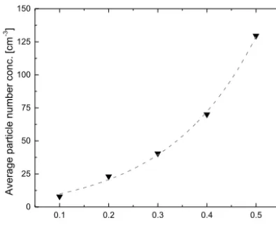
Figure 7.Particle number concentration generated as a function of
Arizona Test Dust mass in the fluidized bed (triangles) with a fitted exponential curve (dashed line).
stage (Figs. 4b, 5b). Particles were observed by the CPC post-sanding and are likely residuals of the post-sanding process; we suggest a thorough cleaning (e.g. via immersion sonication) to eliminate these, although they were observed to asymptote to zero after 450 s (Figs. 4c, 5c). Because no particles were observed in the OPS, we assume their diameter was smaller than 0.3 µm (i.e., below the detection limit of the OPS). In-stalling the porous screen did not cause significant particle generation. Introduction of the bronze beads resulted in an OPS maximum particle concentration of∼1.5 cm−3with a mode at∼2.5 µm in diameter; a similar particle concentra-tion was detected at the CPC. The particle concentraconcentra-tion at this stage could be reduced to∼0.1 cm−3with insertion of a stainless steel tube into the elutriator (Figs. 4e, 5e). This pre-vented direct contact of the bronze beads with the generator wall and indicates that some abrasion of the printed surface can take place.
3.2 Mineral dust experiments
Arizona Test Dust (ATD; Powder Technology Inc., MN, USA) was used as the sample material in this study. The nominal size of particles ranged from 0 to 3 µm and 0.2 g ATD were initially added to the generator. A measurement time of 1200 s was split into two 600 s segments to deter-mine the particle concentration as a function of time. The first 600 s showed a decrease after startup, a brief drop in concentration and then an upward asymptote to∼25 cm−3at
the CPC (Fig. 6a). The size distribution in the OPS remained more or less constant with a final maximum particle concen-tration of ∼25 cm−3 centered at 0.3 µm diameter (Fig. 6b). Although this is the lowest size bin of the OPS, the similarity in CPC and OPS concentrations indicate most generated par-ticles fall within, and towards the low end of, the OPS size range. The second 600 s showed a stable particle concentra-tion from 25 to 30 cm−3 in the CPC (Fig. 6c). The shape
Figure 8. Average particle size distribution with corresponding
standard deviations as a function of optical particle diameter. Parti-cles were generated from a Saudi Arabian arid soil dust sample.
of the size distribution did not change over time, showing the maximum particle concentration remained at ∼0.3 µm (Fig. 6d).
A sensitivity study of the number concentration of ated particles as a function of ATD mass added to the gener-ator was also performed. ATD was added stepwise from 0.1 to 0.5 g to the clean PRIZE with measurements made after an initial 600 s “warm-up” period, the stabilization time indi-cated in the initial experiment. This procedure was repeated at each mass loading. The resulting particle number concen-trations showed an exponential growth with increasing mass load in the fluidized bed from 10 to 150 cm−3 (Fig. 7). A curve fitted to the data provides a particle number concentra-tion (PNC) as a funcconcentra-tion of the mass load (ML) for this ATD sample:
PNC=8.414·exp
ML
0.18081
−4.75126. (1)
A final experiment was conducted to demonstrate the use of PRIZE for dispersion of collected soil dust samples. Fig-ure 8 provides a size distribution of particles dispersed from an arid soil sample collected in Dhahrat Laban (west of Riyadh, Saudi Arabia).
4 Conclusions
This study describes the design, manufacture and proof-of-concept experiments of the 3-D printed fluidized bed genera-tor PRIZE, which is a compact, simple and low-cost addition to existing dry particle generation instruments. The genera-tor is capable of dispersing aerosol particles from dry mate-rial without itself generating significant particles (<5 % by number at 0.2 g of ATD without a stainless steel insert and negligible with an insert). Using SLA technology makes this a low-cost instrument when compared to commercially avail-able FBGs. Furthermore, the generator is compact and easy to set up as it requires only particle-free pressurized gas and gram-quantity samples. It is therefore ideal for use in mini-mally appointed laboratory and field conditions.
We demonstrate the use of PRIZE for collected samples of soil dust and note its use with mass spectrometry or transmis-sion electron microscopy. Due to the preservation of the orig-inal chemical composition of the aerosolized particles, which is a major advantage of dry particle generation, investigations of cloud condensation and ice nucleation potential can be made without aqueous processing artifacts. Furthermore, we demonstrate with calculations that mass loadings larger than 0.5 g could be used in combination with differential mobility separation for production of size-selected aerosols.
M. Roesch et al.: Dry particle generation with a 3-D printed fluidized bed generator 2005 Appendix A
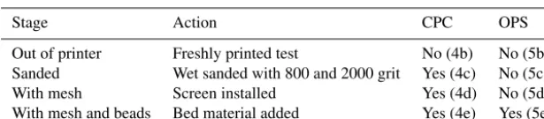
Table A1.PRIZE assembly stages, the action taken and the particle detection results at the CPC and OPS. Corresponding particle number
concentration time-series measurements and size distributions are provided in Figs. 4 and 5, respectively.
Stage Action CPC OPS
Out of printer Freshly printed test No (4b) No (5b)
Sanded Wet sanded with 800 and 2000 grit Yes (4c) No (5c)
With mesh Screen installed Yes (4d) No (5d)
Competing interests. The authors declare that they have no conflict of interest.
Acknowledgements. We acknowledge funding from the Center for Complex Engineering Systems at the King Abdulaziz City for Science and Technology, NSF (AGS-1461347), DOE (DE-SC0014487) and NASA (NNX13AO15G).
Edited by: F. Pope
Reviewed by: two anonymous referees
References
Ardon-Dryer, K. and Levin, Z.: Ground-based measurements of immersion freezing in the eastern Mediterranean, Atmos. Chem. Phys., 14, 5217–5231, https://doi.org/10.5194/acp-14-5217-2014, 2014.
Boucher, O., Randall, D., Artaxo, P., Bretherton, C., Feingold, G., Forster, P., Kerminen, V.-M., Kondo, Y., Liao, H., Lohmann, U., Rasch, P., Satheesh, S., Sherwood, S., Stevens, B., and Zhang, X.: Clouds and Aerosols, in: Climate Change 2013: The Physi-cal Science Basis. Contribution of Working Group I to the Fifth Assessment Report of the Intergovernmental Panel on Climate Change, chapter 7, Cambridge University Press, Cambridge, UK and New York, NY, USA, 2013.
Boucher, R. F. and Lua, A. C.: A stable, high-concentration, dry aerosol generator, J. Aerosol Sci., 13, 499–511, 1982.
Clemente, A., Balas, F., Pilar Lobera, M., Irusta, S., and Santa-maria, J.: Fluidized Bed Generation of Stable Silica Nanoparticle Aerosols, Aerosol Sci. Tech., 47, 867–874, 2013.
Cziczo, D. J., Garimella, S., Raddatz, M., Hoehler, K., Schnaiter, M., Saathoff, H., Moehler, O., Abbatt, J. P. D., and Ladino, L. A.: Ice nucleation by surrogates of Martian mineral dust: What can we learn about Mars without leaving Earth?, J. Geophys. Res.-Planet., 118, 1945–1954, 2013.
Forsyth, B., Liu, B. Y. H., and Romay, F. J.: Particle charge distribu-tion measurement for commonly generated laboratory aerosols, Aerosol Sci. Tech., 28, 489–501, 1998.
Garimella, S., Huang, Y.-W., Seewald, J. S., and Cziczo, D. J.: Cloud condensation nucleus activity comparison of dry-and wet-generated mineral dust aerosol: the significance of soluble material, Atmos. Chem. Phys., 14, 6003–6019, https://doi.org/10.5194/acp-14-6003-2014, 2014.
Gauthier, D., Zerguerras, S., and Flamant, G.: Influence of the par-ticle size distribution of powders on the velocities of minimum and complete fluidization, Chem. Eng. J., 74, 181–196, 1999. Geldart, D.: Types of gas fluidization, Powder Technol., 7, 285–292,
1973.
Guichard, J. C.: Aerosol Generation Using Fluidized Beds, in: Fine Particles: Aerosol Generation, Measurement, Sampling, and Analysis, edited by: Liu, B., Academic Press, New York, 1976. Hartmann, S., Wex, H., Clauss, T., Augustin-Bauditz, S.,
Nieder-meier, D., Roesch, M., and Stratmann, F.: Immersion Freezing of Kaolinite: Scaling with Particle Surface Area, J. Atmos. Sci., 73, 263–278, https://doi.org/10.1175/JAS-D-15-0057.1, 2016.
Hesse, E., Ulanowski, Z., and Kaye, P. H.: Stability characteristics of cylindrical fibres in an electrodynamic balance designed for single particle investigation, J. Aerosol Sci., 33, 149–163, 2002. Hinds, W. C.: Aerosol Technology: Properties, Behavior, and Mea-surement of Airborne Particles, 2nd Edn., Wiley Interscience, New York, 1999.
Hiranuma, N., Moehler, O., Yamashita, K., Tajiri, T., Saito, A., Kiselev, A., Hoffmann, N., Hoose, C., Jantsch, E., Koop, T., and Murakami, M.: Ice nucleation by cellulose and its potential con-tribution to ice formation in clouds, Nat. Geosci., 8, 273–277, 2015.
Kumar, P., Sokolik, I. N., and Nenes, A.: Cloud condensation nuclei activity and droplet activation kinetics of wet processed regional dust samples and minerals, Atmos. Chem. Phys., 11, 8661–8676, https://doi.org/10.5194/acp-11-8661-2011, 2011.
Lind, T., Danner, S., and Guentay, S.: Monodisperse fine aerosol generation using fluidized bed, Powder Technol., 199, 232–237, 2010.
Marple, V. A., Liu, B. Y. H., and Rubow, K. L.: A dust generator for laboratory use, Am. Ind. Hyg. Assoc. J., 39, 26–32, 1978. Mehrani, P., Bi, H. T., and Grace, J. R.: Bench-scale tests to
deter-mine mechanisms of charge generation due to particle–particle and particle-wall contact in binary systems of fine and coarse particles, Powder Technol., 173, 73–81, 2007.
Moreno, F. and Blann, D.: Large Flow Rate Redispersion Aerosol Generator, in: Fine Particles: Aerosol Generation, Measurement, Sampling, and Analysis, edited by: Liu, B., Academic Press, New York, 1976.
Murphy, D. M.: The design of single particle laser mass spectrome-ters, Mass. Spectrom. Rev., 26, 150–165, 2006.
Niedermeier, D., Hartmann, S., Shaw, R. A., Covert, D., Mentel, T. F., Schneider, J., Poulain, L., Reitz, P., Spindler, C., Clauss, T., Kiselev, A., Hallbauer, E., Wex, H., Mildenberger, K., and Stratmann, F.: Heterogeneous freezing of droplets with immersed mineral dust particles – measurements and parameterization, At-mos. Chem. Phys., 10, 3601–3614, https://doi.org/10.5194/acp-10-3601-2010, 2010.
Sullivan, R. C., Moore, M. J. K., Petters, M. D., Kreidenweis, S. M., Roberts, G. C., and Prather, K. A.: Timescale for hygro-scopic conversion of calcite mineral particles through heteroge-neous reaction with nitric acid, Phys. Chem. Chem. Phys., 11, 7826–7837, 2009.
Sullivan, R. C., Moore, M. J. K., Petters, M. D., Kreidenweis, S. M., Qafoku, O., Laskin, A., Roberts, G. C., and Prather, K. A.: Impact of Particle Generation Method on the Apparent Hygro-scopicity of Insoluble Mineral Particles, Aerosol Sci. Tech., 44, 830–846, 2010.
Tang, M. J., Cziczo, D. J., and Grassian, V. H.: Interactions of Water with Mineral Dust Aerosol: Water Adsorption, Hygroscopicity, Cloud Condensation and Ice Nucleation, Chem. Rev., 116, 4205– 4259, 2016.
Tobo, Y., DeMott, P. J., Raddatz, M., Niedermeier, D., Hartmann, S., Kreidenweis, S. M., Stratmann, F., and Wex, H.: Impacts of chemical reactivity on ice nucleation of kaolinite particles: A case study of levoglucosan and sulfuric acid, Geophys. Res. Lett., 39, L19803, https://doi.org/10.1029/2012GL053007, 2012. Wang, Z., Kwauk, M., and Li, H.: Fluidization of fine particles,
M. Roesch et al.: Dry particle generation with a 3-D printed fluidized bed generator 2007