Enhancement of Heat Transfer Rate using
Nano Fluid in Heat Exchanger
SK. Ahmad(1) ,D.Divya Chandrika(2)
Assistant Professor, Department of mechanical engineering, Wellfare institute of science technology and Management, Andhra Pradesh, India
Abstract
Nanotechnology is concerned with the materials and systems whose structures and components exhibit novel and significantly improved physical, chemical, and biological properties, phenomena, and processes due to their nano scale size. In this demonstrates the enhancement of heat transfer using nano fluids in a heat exchanger utilizing commercially available equipment. Experiments will be conducted using both conventional fluid and nano fluid and the overall heat transfer coefficient is compared.
Key words:Nano fluid, Heatexchanger, Conventional Fluid.
I. INTRODUCTION
A heat exchanger is a device used for affecting the process of heat exchange between two fluids that are at two different temperatures. Heat exchangers are useful in engineering process like those in refrigeration and air conditioning systems, power systems, food processing systems, chemical reactors and space or aeronautical applications. In heat exchangers the temperature of each fluid changes as it passes through the exchanger and hence the temperature of the dividing wall between the fluids also changes along the length of the exchanger. Heat exchangers are designed to deliver a certain heat transfer rate for a certain specified condition of flow rates and temperatures. Shell and tube heat exchangers are used when a process requires large amounts of fluid to be heated or cooled, is suited for higher pressure applications. Nano particles research is gaining increasing interest due to their unique properties, such as increased thermal conductivity, toughness and ductility, increased hardness and strength of metals and alloys, luminescent efficiency of semiconductors, formability of ceramics. In order to enhance the heat transfer rate of the heat exchanger, a new category of fluids are used along with the conventional fluids like water, those fluids are called as nano fluids. Nano fluids are those fluids which exhibit significantly novel properties when compared to conventional fluids. Nano fluids are suspensions containing particles that are less than 100nm and have a bulk solids thermal conductivity of orders of magnitude higher than the base fluids.
II. PROBLEM DEFINITON
Using conventional fluids like water in heat
exchangers became a routine part of the
experimentation in order to calculate the overall heat transfer coefficient.
The main objective of our project is to introduce a new class of fluids called nano fluids which can enhance and improve the overall heat transfer coefficient of the heat exchanger. This idea of introducing nano fluids is that nano technology can be implemented in under- graduation levels as nano technology has a great scope and wide range of applications. Incorporation of nano technology in under-graduation level helps the personnel to extend their knowledge over nano technology at the earlier level which in turn help them to do more research on nano materials in various fields.
III. PREPARATION OF COPPER OXIDE NANO FLUID
Stage 1: Measuring the required weight of nano particles to be added to the base fluid.
Stage 2: Preparing the base fluid containing 70% distilled water and 30% ethylene glycol.
Stage 3: Add the nano particles to the base fluid and use sonication process to obtain nano fluid.
A. Sonication
Sonication is a process where the nano particles are subjected to ultrasonic vibrations to stabilize the nano particles.
The base fluid is subjected to magnetic stirring for few hours before dumping the mixture into sonicator.
After magnetic stirring now the mixture is dumped into sonicator and kept for 5 hours.
SEM (Scanning Electron Microscope):
Scanning electron microscope images were obtained for both copper oxide nano particle and copper oxide nano fluid by placing few drops of the dispersion on a copper grid and evaporating them prior to observation. The SEM image of copper oxide nano particles where we can
observe spherical morphology. Figure[1]
Figure 1
Figure 2
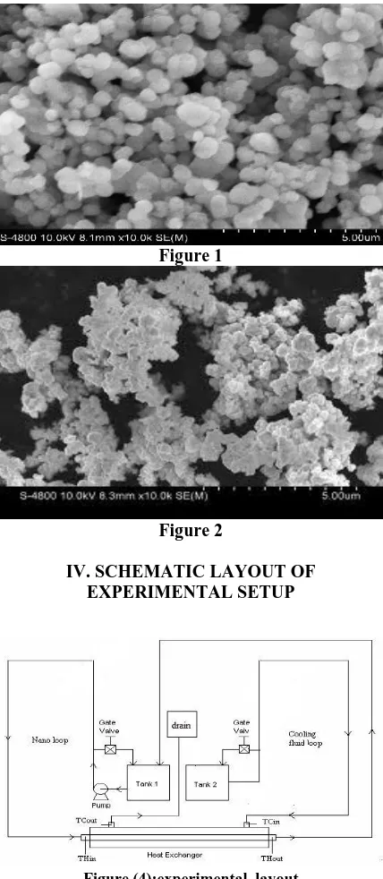
IV. SCHEMATIC LAYOUT OF EXPERIMENTAL SETUP
Figure (4):experimental layout
A. Cooling fluid loop:
The rightmost part of the setup is the cooling fluid loop in the above shown figure[4]
This loop starts from cooling water storage tank called [tank 2].Cooling water from the tank is allowed to pass through the shell side inlet.Now, the cooling fluid flows through the shell at a certain flow rate.Cooling water emerges out from the shell outlet. Now the flow rate of cooling fluid is calculated either manually or using flow meter.The loop ends with the storage tank again by collecting the water.
B. Nano loop:
The leftmost part of the setup is the nano loop in
nano fluid) from the storage tank i.e (tank 1).Before allowing this mixture to pass through the tube inlet, it is heated using a heating unit (geyser).Now, the hot mixture is allowed to pass through the tube inlet.The mixture passes through the tubes and comes out from the tube outlet.It is continuously re-circulated using a re-circulating pump throughout the experiment.
C. 1-shell 2-tube pass heat exchanger
Fig 4.1 1shell 2-tube pass heat exchanger.
Figure (4.2):Experimental setup
D. Working of heat exchanger:
The heat exchanger used in this project is “Shell and Tube heat exchanger”. In this type of heat exchanger, one fluid flows through a bundle of tubes enclosed by a shell. The other fluid is forced through the shell and flows over the outer side surface of the tubes. Such an arrangement is employed where reliability and heat transfer effectiveness is to be improved.
1-SHELL 2-TUBE PASS HEAT EXCHANGER falls under the category of single shell and multiple tubes pass heat exchangers. In this type of heat exchanger the fluid through tube side flows through both the directions. Baffle plates are used to change the direction.
and tube side are measured and overall heat transfer coefficient is calculated. Both shell and tube inlet and outlet temperatures were measured which are helpful in calculating the heat transfer coefficient.
E. Components Of The Shell And Tube Heat Exchanger
Fig 4.3: Overall Components Of The Shell And Tube Heat Exchanger
This shell and tube heat exchanger contains several components. They are:
Shell.
Tube Bundle.
Baffle plates.
Tube sheet.
F. Shell
Shell is the outermost component of the heat exchanger which acts as a casing for the tube bundle
and provides a passage for cold fluid
Fig4.4 Shell
G. Tube bundle
Tube bundle is a collection of tubes which provides a passage for hot fluid to flow through it. Tubes are made of copper. The tube bundle consists of 32 tubes.
Fig 4.5: Cooper tubes
H. Tube Sheet
Tube sheet is a sheet with holes corresponding to the number of tubes. Each tube is inserted into their respective holes of the sheet. There are two tubes sheets at both the ends of the heat exchanger. The tube sheet forms the barrier between the shell and tube fluids
Fig 4.6: Tube sheet
V. METHODOLOGY
Cooling water at room temperature is allowed to flow through shell inlet.
Temperature reading is noted at the shell inlet.. A total volume of 17 liters (water + nano fluid) is
used in this experiment.
Volume of solute is calculated using this formula.
Volume concentrat (%) = Volume of CuO*100
Volume of mixture
2= x *100.
1000
x = 20ml.
For every 1000ml of water, 20ml of copper oxide nano fluid is mixed thoroughly.
A 1liter collecting flask is taken and both water and nano fluid is poured in it and was mixed thoroughly using magnetic stirrer for 15 minutes. The above process is repeated for the whole 17
litres.
Figure(5): Magnetic stirring of water dispersion nano fluid
Now, finally the mixture is collected in the storage tank.
This mixture is pumped to the geyser using re-circulating pump.
The fluid is heated in the geyser and then the hot fluid is allowed to pass through the tube inlet. Temperature reading is noted at tube inlet. As the heat exchanger used in this experiment is
1-Shell 2-Tube pass heat exchanger, the hot fluid passes
through
the tubes in both the directions. Baffle plates are used to change the direction of the fluid.
Heat exchange takes place between the two fluids in the heat exchanger.
After the heat exchange process is completed, the fluids come out through their respective outlets with a certain heat transfer.
Both shell and tube outlet temperature readings are noted.
Flow rate is calculated manually by using a measuring flask and stopwatch.
Now, the overall heat transfer coefficient is calculated using the obtained temperature readings and other parameters.
VI. WATER/WATER EXCHANGE
Table 6.1: Temperature readings
Table 6.2 Flow rates
A. Calculations:
Flow area (A0) = 0.57 m2 Where,
Nt=Number of tubes. d0= Diameter of tube. l= Length of the tube.
Heat removed from hot water (Q) = mh*Cp*(T1-T2) = 1504.8J
Figure6.3: Ft vs. S Graph
From the graph, based on R and S values, Ft = 0.91. True mean temperature (ΔTm) = Ft* Ɵm =10.4ºC Overall heat transfer coefficient (Uo) U0 = Q/ (A0* ΔTm)
= 253.84W/m2◦C
An overall heat transfer coefficient of 253.84W/m2◦C
was obtained using water on both shell and tube side.
VII. WATER/NANO FLUID EXCHANGE:
Table 7.1 Temperature readings
A. Calculations
Flow area (A0) = 0.57 m2 Nt= Number of tubes. d0= Diameter of tube. l= Length of the tube
Heat removed from hot water (Q) = mh*Cp*(T1-T2)
=1652.4J
True mean temperature (ΔTm) = Ft * Ɵm. = 0.87*9.97 = 8.67◦C
Overall heat transfer coefficient (Uo)
U0 = Q/ (A0* ΔTm) = 1652.4/ (8.67*0.57) = 334.36W/m2◦C
An overall heat transfer coefficient of
334.36W/m2◦Cwas obtained using cold water on shell side and hot mixture of nano fluid and water on tube side.
VII. CONCLUSIONS
By comparing the results of both conventional fluid and nano fluid, we got a 24.02% enhancement of overall heat transfer coefficient for a 2% volume concentration of copper oxide nano fluid.
Higher concentrations can be used for much better enhancement of overall heat transfer coefficient.
REFERENCES
[1] Ali Rajabpour1, FarrokhYousefi Akizi2, Mohammad Mahdi Heyhat3 and KiarashGordiz4 :Molecular dynamics simulation of specific heat capacity of water-CuOnanofluids, Int. Journal.MD Simulation(2013)
[2] KamaleshBhakat (Nano labs), Singhbhum, Jamshedpur: Preparation and characterization of nano fluid.
[3] L.B. Mapa1, Sana Mazhar2, Purdue University Calumet, Indiana: Heat transfer in mini heat exchanger using nano fluids.
[4] Xuan Y and Li Q. 2000. Heat Transfer Enhancement of Nanofluids. International Journal of Heat and Fluid Flow. 21: 158-164.
[5] Keblinski P., Philpot S. R., Choi S. U. S. and Eastman J. A. 2002. Mechanisms of heat flow in suspensions of nano-sized particles (nanofluids). International Journal of Heat and Mass Transfer. 45: 855-863.
[6] Process heat transfer by Donald Q . Kern published by McGraw – Hill Book Company.
[7] Xuan, Y.M, Li, Q., (2003). Investigation convective heat transfer and flow features of nano fluids, ASME J. Heat Transfer, 125, 151-155.
[8] Wen Dongsheng and Ding Yulong (2004), Experimental Investigation convective heat transfer of nano fluids at the entrance region under laminar flow conditions, Int. J. Heat and Mass Transfer, 47, 5181-5188.