ISSN: 2231-5381
http://www.ijettjournal.org
Page 387
Design of Radar to Detect a Target at an
Arbitrary Standoff Range
Oenga Jones Ragira
M. Tech Scholar, ECE Department
Sri Venkateswara College of Engineering & Technology, Chittoor-51712,7 A.P. INDIA
Abstract In recent years, the use of different wireless and/or remote sensing techniques for identifying and tracking various objects has increased significantly. The detection and identification of targets navigating a given area are essential in order to prevent accidents and to take counter measures against illegal activities. Usually, radar systems are employed for the detection of objects. An original method for discriminating between electronic targets, by receiving at least two nonlinear mixing products near a harmonic, is presented. Specifically, the upper bounded inter element spacing provides a correct angular sampling accordingly to the Nyquist theorem and the lower bounded number of elements of the array ensures the continuity of the observation during multiple scans. (Radio Frequency Interference)RFI is particularly disruptive to harmonic radar since the signal-to-noise ratio of the second order nonlinearity as is the case with traditional linear radar hence signal-to- interference-plus-noise ratio (SINR) decreases. Improved transponder design, MIMO, spectrum sensing, compressive sensing, adaptive bandwidth are among the techniques current in play for an improved performance of Radars. Harmonic radar are inherently highly sensitive. The harmonic radar must therefore avoid interference that could saturate the RF components and drive the RF components into their nonlinear operating region causing self-induced harmonics. It’s vital that a Radar system mitigates the effect of RF in order to improve its efficiency.
In this work, Multitone harmonic radar is presented. The radar transmits multiple closely-spaced tones and receives nonlinear mixing products as well as harmonics. Harmonic and Multitone responses are recorded from commercially-available RF devices. . By properly designing the array of passive devices, the system is able to correctly observe the signal reflected from the targeted electronic device over successive scans of the radar. Target detection is demonstrated experimentally for a novel pulsed two-tone harmonic radar. Experimental results are extrapolated to estimates radar design parameters to achieve an arbitrary standoff range of the object.
Keywords— Inverse synthetic aperture radar, Very High frequency (VHF), Ultra High frequency (UHF), synthetic aperture radar (SAR), Automatic Detection and Track (ADT), Device Under Test (DUT), Cathode Ray Tube(CRT) , MATLAB , Frequency-modulated continuous-wave (FM-CW)
I.INTRODUCTION
Radar is very complex electronic systems. The term radar is an acronym for the RAdio Detection and Ranging, Radars exploits electromagnetic energy to detect objects. It is classified as air bone, ground based, ship based radar systems, or space borne. They are classified into categories based on their specific radar characteristics namely antenna type and frequency band. They may be classified in accordance to the mission and functionality of the radar. This includes acquisitions, weather and search, tracking, over the horizon track-while-scan, fire control, over the horizon, early warning, terrain following and are often called multifunction radars. Radars are also classified by the type of waveforms or operating frequency. Radar can be Continuous Wave (CW) or Pulsed Radar (PR). The types of RADAR include Simple pulse radar, Moving-target indication (MTI) radar, Airborne moving-target indication (AMTI) radar, Pulse Doppler radar (with high pulse-repetition frequency),Pulse Doppler radar (with medium pulse-repetition frequency), High-range-resolution radar, Pulse-compression radar, Synthetic aperture (SAR), Inverse synthetic aperture radar (ISAR), Side-looking airborne radar (SLAR), Imaging radar, Tracking radar, Track-while-scan radar, 3D radar, Electronically scanned phased-array radar, Continuous-wave (CW) radar, Frequency-modulated continuous-wave (FM-CW) radar High frequency (HF) radars utilize the electromagnetic waves reflection off the ionosphere layer to detect targets beyond the horizon. Very High frequency (VHF) and Ultra High frequency (UHF) bands are used in the very long range Early warning Radars (EWR). Radar can be defined as active device that carries its own transmitter and doesn’t depend on radiation, as optical and infrared sensors. Radar is able to detect small targets that are far or near and can measure its range with precision in all weather, the main advantage when compared with other sensors.
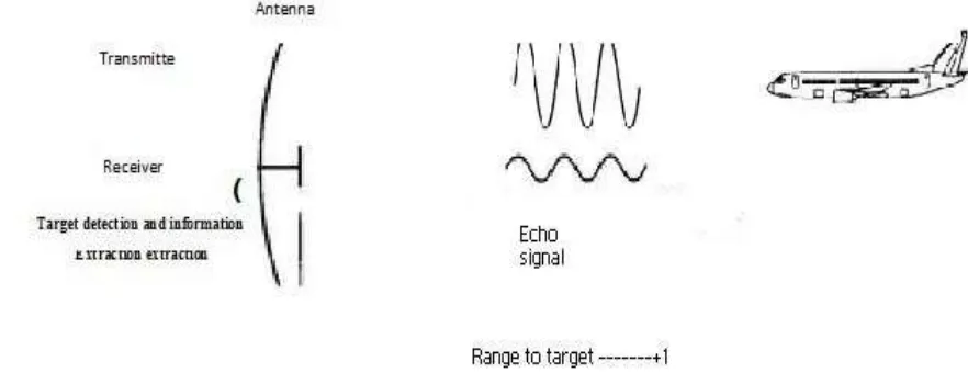
Although modern radar systems are very complicated, it can easily understand their operation by using a basic block diagram of a pulse-radar system. The concept of radar is relatively simple even though in many instances its practical implementation is not. A radar operates by radiating electromagnetic energy and detecting the echo from reflecting objects (targets). The nature of the echo signal provides information about the target. The range, or distance, to the target is found from the time it takes for the radiated energy to travel to the target and back. The angular location of the target is found with a directive antenna (one with a narrow beam width) to sense the angle of arrival of the echo signal. If the target is moving, a radar can derive its track, or trajectory, and predict the future location. The shift in frequency of the received echo signal due to the Doppler effect caused by a moving target allows a radar to separate desired moving or stationary targets from undesired stationary targets even though the stationary echo signal may be many orders of magnitude greater than the moving target. With sufficiently high
resolution, a radar can discern something about the nature of a target's size and shape.
Radar resolution can be obtained by range or angle, or both. Range resolution requires large bandwidth. Angle resolution requires (electrically) large antennas. Resolution in the cross-range dimension is usually not as good as the resolution that can be obtained in range. Even though, when there is relative motion between the individual parts of a target and the radar, it is possible to use an inherent resolution in Doppler frequency to resolve in cross-range dimension. The cross- cross-range resolution of synthetic aperture radar (SAR) for imaging a scene let’s say as terrain can be explained as being due to resolution in Doppler, although the SAR is thought to be a generating a large "synthetic" antenna for storing received signals in a memory. The two views that Doppler resolution and synthetic antenna are equivalent. Resolution in the Doppler domain is a natural way to envision the cross-range resolution achieved by the inverse synthetic aperture radar (ISAR) used for the imaging of a target.
ISSN: 2231-5381
http://www.ijettjournal.org
Page 389
Radar is an active device in that it carries its owntransmitter and does not depend on ambient radiation, as do most optical and infrared sensors. Radar can detect relatively small targets at near or far distances and can measure their range with precision in all weather, which is its chief advantage when compared with other sensors. The principle of radar has been applied from frequencies of a few megahertz (HF, or high-frequency region of the electromagnetic spectrum) to well beyond the optical region (laser radar). The particular techniques for implementing radar differ greatly over this range of frequencies, but the basic principles remain the same.
Radar was originally developed to satisfy the needs of the military for surveillance and weapon control. Military applications have funded much of the development of its technology. However, radar has seen significant civil applications for the safe travel of aircraft, ships, and spacecraft; the remote sensing of the environment, especially the weather; and law enforcement and many other applications. Figures 1.1 show us the basic principle of Radar.
II. THE SYSTEM
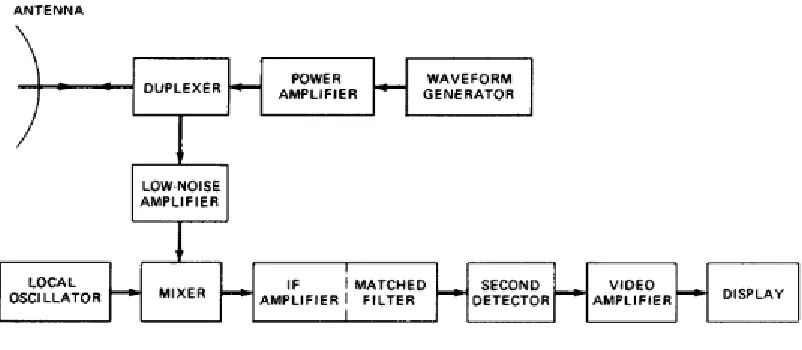
The basic parts of a radar system are illustrated in the simple block diagram of Fig. 2. The radar signal, usually a repetitive train of short pulses, is generated by the transmitter and radiated into space by the antenna. The duplexer permits a single antenna to be time-shared for both transmission and reception.
Reflecting objects (targets) intercept the reradiate portion of the radar signal, the small amount of which is returned towards the direction of the radar. The returned echo signal is collected by the radar antenna and amplified by the receiver. If the output of the radar receiver is sufficiently large, detection of a target is said to occur.
The operation of the radar is described in more detail, starting with the transmitter. The transmitter generates powerful pulses of electromagnetic energy at precise intervals. The required power is obtained by using a high-power microwave oscillator or a microwave amplifier that is supplied by a low- power RF source. Transmitters does not only generate high power with stable waveforms, but they must often operate over a wide bandwidth, with high efficiency and with long, trouble-free life. A radar determines the location of a target in range and angle, but the echo signal provides information about the nature of the target. The output of the receiver may be presented on a display to an operator who makes the decision as to whether or not a target is present, or the receiver output can be processed by electronic means to automatically recognize the presence of a target and to establish a track of the target from detections made over a period of time. With automatic detection and track (ADT) the operator usually is presented with the processed target track rather than the raw radar detections.
The duplexer acts as a rapid switch to protect the receiver from damage when the high-power transmitter is on. On reception, with the transmitter off, the duplexer directs the weak received signal to the receiver rather than to the transmitter. Duplexers generally are some form of gas-discharge device and may be used with state or gas-discharge receiver protectors. A solid-state circulator is sometimes used to provide further isolation between the transmitter and the receiver. The receiver is almost always super heterodyne. The input, or RF, stage can be a low-noise transistor amplifier. The mixer and local oscillator (LO) convert the RF signal to an intermediate frequency (IF) where it is amplified by the IF amplifier. The signal bandwidth of super heterodyne receiver is determined by bandwidth of its IF stage. The IF amplifier is followed by a crystal diode, which is traditionally called the second detector or demodulator. Its purpose is to assist in extracting the signal modulation from the carrier.
The combination of IF amplifier, a second detector, and video amplifier usually act as an envelope to pass the pulse modulation (envelope) and reject the carrier frequency. In radars that Doppler shift of the echo signal, the envelope detector is replaced by a phase detector, which is different from the envelope detector shown. The combination of IF amplifier and is designed to provide sufficient amplification, gain, to raise the level of the input signal to a magnitude where it can be seen on a display, such as a cathode-ray tube (CRT), or be the input to a digital computer foe further processing. At the output of the receiver a decision is made whether or not a target is present. The decision is based on the magnitude of the receiver output. If the output is larger enough to exceed a predetermined threshold, the decision is that a target is present.
If it does not cross the threshold level is set so that the rate at which false alarms occur due to noise crossing the threshold (in the absence of signal) is below some specified, tolerable value. This is fine if the noise remains constant, as when receiver noise dominates. If, on the other hand, noise is external to radar (as from unintentional or from deliberate noise jamming) or if clutter echoes (from the natural environment) are larger than the
echo pulses from a target. The process of adding these pulses together to obtain a greater signal-to-noise ratio before the detection decision is made is called integration. The integrator is often found in the video portion of the receiver. The signal processor is that part of the radar whose function is to pass the desired echo signal and reject unwanted signals, noise, or clutter. The signal processor is found in the receiver before the detection is made. Some radars process the detected target signal further, in the data processor, before displaying the information to an operator. An example is an automatic Tracker, which uses the locations of the target measured over a period of time to establish the track (or path) of the target. Most modern air-surveillance radars and some surface-air-surveillance radars generate target tracks as their output rather than simply display detections. Following the data processor, or the decision function if there is no data processor, the radar output is displayed to an operator or used in a computer or other automatic device to provide some further action. The signal processor and data processor are usually implemented with digital technology rather than with analogue circuitry. The analogue-to-digital (A/D) converter and digital memory are therefore important in modern radar system. In some sophisticated radars in the past, the signal and data processors were larger and consumed more power than the transmitter and were a major factor in determining the overall radar system reliability; but this should not be taken as true in all cases.
A. Radar Subsystem
Basic parts of a typical radar system. The transmitter generates the high-power signal that is radiated from the antenna. The antenna is often in the shape of a parabolic reflector, similar in concept to an automobile headlight but much different in construction and size. It also might consist of a collection of individual antennas operating together as a phased-array antenna.
1. Transmitters
ISSN: 2231-5381
http://www.ijettjournal.org
Page 391
local oscillator, which generates the frequencythat beats with the incoming signal to produce the IF. Bandwidth is the inverse of the pulse width, with a wider bandwidth for narrow pulses. In receivers that use crystal mixers, the power required of the local oscillator is small, only 0 to 50 milliwatts in the 4000-MHz region. Because of the very loose coupling, only about 1 milliwatts actually reaches the crystal. Selected, the power available will be too small. Usually, the 1-3/4 or 2-3/4voltage mode is found suitable. Since the modes are not symmetrical, the point of operation is usually a little below the resonant frequency of the cavity. Both FM and AM signals are undesirable and are classified as noise. Therefore, extra care in tuning and maintenance of the power supplies is required to minimize FM and AM noise generation.
B. The Modulator
The next stage of a radar system is modulator. The modulator is considered to be heart of the radar system and generates all the necessary timing pulses (triggers) for use in the radar and associated systems. Its function is to ensure that all subsystems making up the radar system operate in a definite time relationship with each other and that the intervals between pulses, the pulses are of the proper length.
C. The Transmitter
The radar system’s transmitter increases the power of the oscillator. The transmitter amplifies the power from the level of about 1 watt to as much as 1 megawatts, or 1 million watts. Radar signals have such high power levels because so little of the original signal comes back in the return.
2. Receivers
Receiver accepts the weak RF echoes from the antenna system and routes them to the indicator as discernible signals. Because the radar frequencies are very high and difficult to amplify, super heterodyne receiver is used to convert the echoes to a lower frequency, called the intermediate frequency (IF), which is easier to amplify.
A. The Duplexer
The duplexer acts as a rapid switch in order to protect the receiver from damage when the high-power transmitter is on. On reception, with the transmitter off, the duplexer directs the weak received signal to the receiver rather than to the transmitter. Duplexers are some form of gas-discharge device and may be used with solid-state or gas-discharge receiver protectors. A solid-state
circulator sometimes is used to provide further isolation between the transmitter and the receiver.
B. Signal Processing
Engineers have never agreement as to what constitutes the signal-processing portion of the radar, but it is considered to be the processing whose purpose is to reject undesired signals (such as clutter) and pass desired signals due to targets. It is performed prior to the threshold detector where the detection decision is made. Signal processing includes the matched filter and the Doppler filters in MTI and pulse Doppler radar. Pulse compression, which is performed before the detection decision is made, is sometimes considered to be signal processing, although it does not fit the definition precisely.
C. Data Processing
This is the processing done after the detection decision has been made. Automatic tracking is the chief example of data processing. Target recognition is another example. It is best to use automatic tracking with a good radar that eliminates most of the unwanted signals so that the automatic tracker only has to deal with desired target detections and not undesired clutter. When a radar cannot eliminate all nuisance echoes, a means to maintain a constant false- alarm rate (CFAR) at the input to the tracker is necessary. It also results in a loss in signal-to-noise ratio, and it degrades the range resolution.
D. The Displays
The display for surveillance radar is usually a cathode-ray tube with a PPI (plan position indicator) format. Older radars presented the video output of the receiver (called raw video) directly to the display, but more modern radars generally display processed video, that is, after processing by the automatic detector or the automatic detector and tracker (ADT). These are sometimes called cleaned-up displays since the noise and background clutters are removed.
3. Factors Affecting Radar Performance
The performance of a radar system can be judged by the following: (a) the maximum range at which it can see a target of a specified size, (b) the accuracy of its measurement of target location in range and angle, (c)
jamming (if a military radar), (e) its ability to recognize the type of target, and (f) its availability (ability to operate when needed), reliability, and maintainability.
III. MULTITONE TRANSMIT SIGNAL
Since the responses near 2f0 tend to be the strongest among the received harmonics for the devices of interest to this study, M = 2 is selected for further analysis under excitation by additional simultaneous tones, N > 2.
A. Theory
Let the electric field incident upon the nonlinear Target be the Multitone waveform
(1)
Common phase across all tones generates the highest peak amplitude for a multitoned signal. Applying the highest electric field amplitude to the DUT generates the strongest nonlinear response. By convolving the frequency-domain representation of this waveform with itself, the dominant nonlinear response (k = 1) near 2f0 is obtained:
(2)
B. Measurements
For N = 2 the reflected powers are
(3)
(4)
Fig. 3. Multitone responses received from two targets: Target 1 (above, f0 = 790 MHz) and Target 2(below, f0
= 990 MHz), Ptrans = 27 dBm, f = 40 kHz.
.
(5)
Comparison of Theoretical and Measured M ultitone Responses s 790 MHz and for N = 8, the reflected powers are as follows all values in dB
TABLE I
Frequency Theory
value
Simulation
value
Defer
ence
2fo±∆f -2.3 -2.3 0.0
2fo±2∆f -6.0 6.5 0.5
2fo±3∆f -12.0 12.78 0.78
For both Targets, values for Power Received at 2fo+f differ from theoretical values derived in equation n (3) and (5) by not more than 0.78 dB
Comparison of Theoretical and Measured Multitone Responses for fo is 990Mhz and N=8 all values are in dB
TABLE II
Frequency Theory
value
Simulation
value
Defer
ence
ISSN: 2231-5381
http://www.ijettjournal.org
Page 393
For both Targets, values for Power Received at2fo+f differ from theoretical values derived in equation n (3) and (5) by not more than 1.41 dB
V. PULSED 2-TONE HARMONIC RADAR
Nonlinear radar systems are pulsed or chirped in order to determine range to the target [7, 26]. Unfortunately, pulsing the transmit waveform for a given peak power results in a lower average power-on-target and thus a lower average received response. In this section the fall-off in received signal with pulse duty cycle is derived, and measurements are taken which confirm this theoretical fall-off. The measurements also indicate that transmitting and receiving pulsed multitones is a feasible technique for a practical nonlinear radar.
A. Theory
Let the transmitted multitones given by (39) be pulsed simultaneously with duty cycle Dc
(6)
Where u(t) is a step function with amplitude 1 and thus s(t) is an on-off switching waveform with period Ts .In the frequency domain, Ein becomes
(7)
Where fs = 1/Ts and κ = –∞ to + ∞ are the spectral
Components produced by pulsing Ein (t) with s(t).
The ratio of the power contained in all of the components |κ | > 0 to the power at the fundamental tones κ = 0 is
(8)
Assuming steady-state for the target response, when transmitting pulsed tones instead of CW
tones, the nonlinear responses derived previously are scaled by the square of the pulse duty cycle D2 and now Ptrans Power transmitted by the harmonic pulse. For a radar whose duty cycle is 10%, the average received nonlinear power is expected to be 20 dB lower than a CW radar for the same available RF power. Note some SNR caused by the drop-off in received signal may be recovered with integration
V. RESULTS
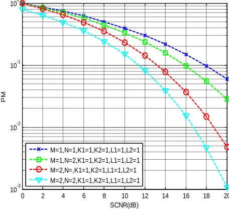
The results compares the number of Receivers antenna to the number of transmitting antenna in relation to the number of signal sent and received and if the signals are echoed. The N represents the number of transmitters while M represents of receivers, similarly the K1 is the number of tones from the transmitter in case of one transmitter transmitting the signal noted as forward path signal. K2 is the no of tones from the transmitter in case of second transmitter transmitting the signal noted as forward path signal. Note that K1 and K2 can be single tone or Multi tone. L1is the number of tones received by the receiver after being echoed by the target at the receiver antenna they are known as feedback path. L2 is the number of tones received by the receiver after being echoed by the target at the in case of a second receiver antenna the signal noted as feedback path signal. Our graphs are plotted in terms of the PM which is the probability of missing target vs the SCNR Signal-Cluster noise ratio.
0 2 4 6 8 10 12 14 16 18 20 10-3
10-2 10-1 100
SCNR(dB)
PM
M=1,N=1,K1=1,K2=1,L1=1,L2=1 M=1,N=2,K1=1,K2=1,L1=1,L2=1 M=2,N=,K1=1,K2=1,L1=1,L2=1 M=2,N=2,K1=1,K2=1,L1=1,L2=1
The above diagram gives a comparison a single tone signal for both the received and transmitted which is both for the forward path and the feedback path. The above compares the case where we have M the transmitting transponder varied between one and two (multiple) numbers as well as compare the case where we have N the receiving transponder varied between one and two (multiple) numbers. Note that the probability of not missing improves with the increase in the number of transmitting antenna and as well as the Signal cluster noise ratio is tremendous improved.
0 2 4 6 8 10 12 14 16 18 20
10-5 10-4 10-3 10-2 10-1 100
SCNR(dB)
PM
M=2,N=2,K1=1,K2=1,L1=1,L2=1 M=2,N=2,K1=2,K2=1,L1=1,L2=1 M=2,N=2,K1=1,K2=1,L1=2,L2=1 M=2,N=2,K1=1,K2=1,L1=1,L2=2
Fig 4.3 Simulated results
The above diagram gives a comparison a single tone signal for both the received and transmitted which is both for the forward path and the feedback path. The above compares the case where we have M the transmitting transponder varied between one and two (multiple) numbers as well as compare the case where we have N the receiving transponder varied between one and two (multiple) numbers. Note that the probability of not missing improves with the increase in the number of transmitting antenna and as well as the Signal cluster noise ratio is tremendous improved. Here we focus more on the number of multitones signal received in relation to the number of multitone signal sent to the target. Further the probability of not missing a target
account the existence of MIP, based on the MQP ionospheric model, the received signal model of the radar has been developed for possible point target. The correlation between any two equivalent reflection coefficients has been derived. This correlation was shown to depend on system parameters such as the target size, target position, antenna positions, operating frequencies, ionosphere layer base hight, ionosphere layer semi-thickness, and ionosphere electron density. Conditions for judging whether the reflection coefficients associated with different propagation paths are correlated or approximately uncorrelated have been provided.
This paper has presented an overview on harmonic radar and transponders. The concept provides a means of obtaining improved object detection in areas with environmental clutter. Different ways of implementing harmonic transponders have been investigable exploited and compared. Transponders of various shapes and sizes can be found from the literature for various frequencies and applicable uses. Potential techniques for characterizing the properties of harmonic transponders have also been discussed, and their possibilities and limitations are also considered as well.
The application of the developed signal model was illustrated by a target detection example. Under the assumptions of orthogonal transmitted signals and complex Gaussian clutter-plus-noise, the optimum detector under the NP criterion has been derived for an example case. The detection performance was studied. It has been proved that for the studied case, diversity gain for target detection using MQP. This is an interesting finding which demonstrates that a diversity of can be obtained even when the receive antennas are closely spaced, as long as the total number of backward paths is large enough, which demonstrates the benefits of having the MIP phenomenon.
Future and ongoing work in the field includes investigating further alternative design strategies including wider use of transponders with external matching circuits, as well as considering possible novel applications for the harmonic radar concept.
References
ISSN: 2231-5381
http://www.ijettjournal.org
Page 395
Aerospace and Electronic Systems, vol. 12, no. 2, pp. 230–245, 1976.
[4] J. Shefer and R. J. Klensch, ―Harmonic radar helps autos
avoid collisions,‖ IEEE Spectrum, vol. 10, no. 5, pp. 38–45,
1973.
[5] H. Staras and J. Shefer, ―Harmonic radar detecting and ranging system for automotive vehicles,‖ US Patent 3781879, 1973.
[6] H. Kwun, G. L. Burkhardt, and J. L. Fisher, ―Detection of reinforcing steel corrosion in concrete structures using non- linear harmonic and intermodulation wave generation,‖ US Patent 5 180 969, 1993.
[7] J. R. Riley and A. D. Smith, ―Design considerations for an harmonic radar to investigate the flight of insects at
low altitude,‖ Computers and Electronics in Agriculture, vol.
35, no.2-3, pp. 151–169, 2002.
[8] G. L. Charvat, E. J. Rothwell, L. C. Kempel, and T.
Miller, ―Harmonic radar tag measurement and
characterization,‖ in Proceedings of the IEEE Antennas
and Propagation Society International Symposium, vol. 2, pp. 696–699, IEEE, Columbus, Ohio, USA, June 2003.
[9] J. Saebboe, V. Viikari, T. Varpula et al., ―Harmonic
automotive radar for VRU classification,‖ in Proceedings of the
International Radar Conference “Surveillance for a Safer World” (RADAR ’09), pp. 1–5, Bordaux, France, October 2009. [10] Z.-M. Tsai, P.-H. Jau, N.-C. Kuo et al., ―A
high-range-accuracy and high-sensitivity harmonic radar code for bee
searching,‖ IEEE Transactions on Microwave vol. 61, no. 1, pp.
666–675, 2013.
[11] G. L. Lo¨vei, I. A. N. Stringer, C. D. Devine, and M.
Cartellieri, ―Harmonic radar—a method using inexpensive
tags to study invertebrate movement on land,‖ New Zealand
Journal of Ecology, vol. 21, no. 2, pp. 187–193, 1997.
[12] G. Brooker, Introduction to Sensors for Ranging and
Imaging, SciTech Publishing, 2009.
[13] K.-L. Wong, Planar Antennas for Wireless
Communications, John Wiley & Sons, 2003.
[14] L. Chioukh, H. Boutayeb, D. Deslandes, and K. Wu, ―Noise and sensitivity of harmonic radar architecture for remote
sensing and detection of vital signs,‖ IEEE Transactions on
Microwave Theory and Techniques, vol. 62, no. 9, pp. 1847– 1855, 2014.
[15] D. Psychoudakis, W. Moulder, C.-C. Chen, H. Zhu, and J. L.
Volakis, ―A portable low-power harmonic radar system
and conformal tag for insect tracking,‖ IEEE Antennas and
Wireless Propagation Letters, vol. 7, pp. 444–447, 2008. [16] H. M. Aumann and N. W. Emanetoglu, ―A constant
beamwidth reflector antenna for a harmonic radar
operating in the near- field,‖ in Proceedings of the 16th
International Symposium on Antenna Technology and Applied Electromagnetics (ANTEM
’14), p. 2, Victoria, Canada, July 2014.
[17] S. Cheng, P. Hallbjo¨rner, and A. Rydberg, ―Array antenna
for bodyworn automotive harmonic radar tag,‖ in Proceedings
of the
3rd European Conference on Antennas and Propagation (EuCAP
’09), pp. 2823–2827, Berlin, Germany, March 2009.
[18] K. Rasilainen, J. Ilvonen, and V. Viikari, ―Antenna matching at harmonic frequencies to complex load
impedance,‖ IEEE Antennas and Wireless Propagation Letters,
vol. 14, pp. 535–538, 2015.
[19] P. V. Nikitin, K. V. S. Rao, S. F. Lam, V. Pillai, R. Martinez, and H. Heinrich, ―Power reflection coefficient
analysis for complex impedances in RFID tag design,‖ IEEE
Transactions on Microwave Theory and Techniques, vol. 53, no. 9, pp. 2721–2725,2005.
[20] H. C. Gomes and N. B. Carvalho, ―The use of intermodulation distortion for the design of passive RFID,‖ in Proceedings of the 37th European Microwave Conference (EUMC ’07), pp. 1656–1659, Munich, Germany, October 2007.
[21] Ayesha Qamar, U m ar Faruq Modelling and Simulation of UWB
Radar System for Through the Wall Imaging and Doppler