164502-7979-IJMME-IJENS © April 2016 IJENS I J E N S
Effect of Surface Roughness and Taper Angle on
Junction Strength of Modular Biomedical Implant
Mohammad Reza Yavari, Mohd Hasbullah Idris
Faculty of Mechanical Engineering, Universiti Teknologi Malaysia (UTM), 81310 Johor Bahru, Malaysia
Abstract-- One of the most common problems with modular implants is that they begin to loosen over time. Implant loosening issue is of concern to physicians since implant revision surgery is an extremely difficult operation. A stable fixation between modular taper junctions is necessary to prevent motion and corrosion. There are many factors that can affect the loosening problem. This study aimed to determine the influence of surface roughness and taper angle on junction strength of modular biomedical implant in two different compression forces including 1500N and 2500N. The study was carried out on three different taper angles including 2°, 4° and 6° and surface roughness ranging from 1 to 4.18µm, to keep track of changes in pull out force. The results obtained in this study demonstrated that taper angle and surface roughness affect the pull out force. The highest pull out force was observed at smoother surface roughness and tighter taper angles, declining gradually in rougher surfaces and drastically in wider taper angles. It can be inferred that implants are less likely to be loosened in 1.04µm surface roughness and taper angle 2° considering the scope of experiments.
Index Term--modular implant, surface roughness, taper angle, pull out force, disassembly strength
1 INTRODUCTION
Modular taper implants were introduced in 1970s [1]. Application of modular taper implants have been gradually increased especially in total hip replacement operations, dental implants, abutment systems, head-neck or any other junction between two implants [2][3]. Modular taper is one of the most recommended implant methods which provides some advantages such as high gripping force, self-locking mechanism and symmetric adherence between the two components [4][5][6]. Thus, Modular taper implants simplify the surgical procedure by allowing the surgeon to fulfill the patient needs intraoperatively [7][8]. However, implant modularity have some drawbacks such as micro-motion, crevice corrosion and fretting which occur under loading situation which leads to loosening the modular implant [4]. Implants are usually designed in a removable fashion in order to simplify the revision surgery. Hence, the surgeons generally prefer short stems, which are easier to extract than longer ones [9]. Revision surgery is usually performed in case of implant failure such as loosening which may induce infection, allergy and inflammation [10]. Implant loosening is one of the most common problems with fitted modular taper implants which completely affects the proper functionability of the patient [11][12][13]. It has been discovered that this issue leads to patient discomfort by increasing pain and loss of motion [7]. In biological terminology, this situation is known as implant loosening failure which mainly occurs due to lack of rigid
taper connection and overload [14]. Poor taper connection strength can lead to unintended disassembly. With the increasing popularity of modular biomedical implant method, the need to achieve a secure junction strength is essential [15]. This study aimed to apply different taper angles and surface roughness conditions to figure out more secure junction strength. The result of this study can be implemented in order to contribute to improve the fitting modular strength of a shaft and hub as a biomedical implant. As a result, reducing the probability of the implant loosening would reduce the expected implant failure which cause the infection, continuous pain and harsh inflammation for the patients.
The Morse taper is adopted from design and manufacture of metal cutting tools for use in orthopaedic surgery 40 years ago [16][17]. Morse tapers are not standardized in the orthopaedic industry; they vary from manufacturer to manufacturer. A range of different Morse taper angles and surface roughness exist within commercially available implants. Morse taper
angles used in implant industry generally fall in 2˚-15˚ domain
[18]. Various studies have addressed the effects of factors such as impact force, number of impacts required to assemble, dryness of the taper components on the junction strength. However, taper manufactures are still challenged by the lack of information of other factors such as the taper angle and surface roughness of matting surfaces [4]. Few investigations have focused on the influence of the different matting surface roughness on the junction strength. Sancaktar and Gomatam [19] considered the surface roughness range around Ra = 2.0
µm as maximum static load bearing capacity of joint. Lee et al.
164502-7979-IJMME-IJENS © April 2016 IJENS I J E N S
2 METHODOLOGY
In order to measure the effect of surface roughness and taper angle on junction strength in this study, a series of implant samples were developed with different range of surface roughness and taper angle. Figure 1 shows the taper angle definition. The methodology of this study consisted of three phases, including: 1. Sample preparation, 2. Assembly fitting, 3. Disassembly. The following sections describe each phase in more detail.
Fig. 1. Taper angle definition 2.1 Phase 1. Sample Preparation
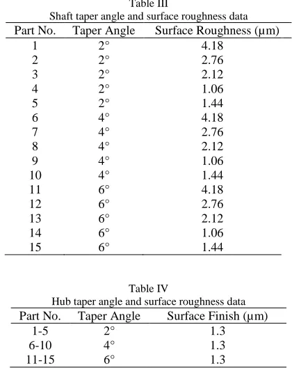
In this study, the term “shaft” refers to the “male” component and the term “hub” denotes the “female” component of the modular junction. Fifteen biomedical implant samples were used in this study. Each sample consists of one shaft and one hub as shown in Figure 2. The material of all implant samples was stainless steel 316. All samples were machined by Maho Granziano GR200E 2-Axis CNC lathe machine by regulating the spindle speed and feed rate while the cutting tool and cutting conditions such as coolant, depth of cut and temperature remained constant [22]. Tables 1 and 2 indicate the cutting condition for all fifteen shafts and hubs.
Fig. 2. Shaft and hub of implant sample
Table I Shaft Machining Condition
Part No. Spindle Speed
(rpm)
Feed Rate (mm/rev)
Depth of Cut (mm)
1,6,11 500 0.3 0.5
2,7,12 800 0.18 0.5
3,8,13 1100 0.13 0.5
4,9,14 1500 0.1 0.5
5,10,15 2000 0.05 0.5
Table II Hub Machining Condition
Part No. Spindle Speed
(rpm)
Feed Rate (mm/rev)
Depth of Cut (mm)
1 - 15 800 0.1 0.5
2.1.1 Taper Angle and Surface Roughness
In terms of taper angle, the samples were machined at 3 different taper angle groups i.e. five shaft-hub pairs with taper
angle of 2°, five shaft-hub pairs with taper angle of 4° and five
shaft-hub pairs with taper angle of 6°. For surface roughness,
each group was machined in five different machining conditions which produced five different surface roughness
between = 1μm and 4.18μm. In other words, for each taper
angle five different surface roughness were investigated. The surface roughness and taper angle of all samples were measured by surface roughness measuring instrument Mitutoyo Formtracer CS-5000 to ensure accuracy and integrity of the production. Shaft-hub samples specifications are shown in Tables III and IV.
Table III
Shaft taper angle and surface roughness data
Part No. Taper Angle Surface Roughness (µm)
1 2° 4.18
2 2° 2.76
3 2° 2.12
4 2° 1.06
5 2° 1.44
6 4° 4.18
7 4° 2.76
8 4° 2.12
9 4° 1.06
10 4° 1.44
11 6° 4.18
12 6° 2.76
13 6° 2.12
14 6° 1.06
15 6° 1.44
Table IV
Hub taper angle and surface roughness data
Part No. Taper Angle Surface Finish (µm)
1-5 2° 1.3
6-10 4° 1.3
11-15 6° 1.3
2.2 Phase 2. Press-Fit Assembly
164502-7979-IJMME-IJENS © April 2016 IJENS I J E N S
Assembly process was automatically stopped when the compression forces reached to its maxima (1500 or 2500 N) [27][12].
2.3 Phase 3. Pull Off Test – Disassembly
Pull-off test is the most common method used to determine the junction strength between shaft and hub. For all the assembled shaft-hub pairs pull-off test was performed at pull out force rate of 0.5 mm/min using the INSTRON 8801 servohydraulic testing instrument according to ISO 7206-10 [15]. Pull-out force gradually increased until turn off moment (the moment when two parts become disconnected) ocurred. Figure 3 shows the pull off test procedure.
Fig. 3. Pull off test experiment at a rate of 0.5 mm/min using the INSTRON 8801 servohydraulic testing system
3 RESULTS
Figures 4 and 5 show the effect of surface roughness on junction strength at 1500N and 2500N compression force respectively. The horizontal axis denotes the surface roughness which varies between 1 to 4.5 µm while the vertical axis displays the pull-out force. In both compression forces it can be observed that pull out force was significantly altered between different taper angles. According to Figures 4 and 5, pull out force at taper angle 2° is the highest among its counterparts, 2963N in 1500N compression force and 5946N in 2500N compression force. Regardless of the applied compression force, taper angle 4° has lower pull out force compared to taper angle 2°. The lowest pull out force was observed at taper angle 6° with 718N in 1500N compression force and 1146N in 2500N compression force.
In 1500N compression force (Figure 4), a slight reduction in pull out force has been observed in 2° and 4° taper angles from 2963N to 2260N (slope of 220.6) and from 2033N to 1622N (slope of 143.4) respectively. However, the downward trend was more pronounced at 2° taper angle. Surprisingly, the variations of surface roughness for 6° taper angle had almost no effect on the pull out force (negligible slope). According to the experiment result, in 1500N compression force, the effect of surface roughness on pull out force was not significant. The effect of surface roughness on pull out force has been intensified in 2500N compression force. In Figure 5, it can be observed that in 2° and 4° taper angle, pull out force has been significantly reduced from 5946N to 3856N (slope of 675.1) and from 4168N to 2988N (slope of 352.4) respectively. However, unlike the experiment with 1500N compression force, 6° taper angle reflected a slight reduction (slope of
112.3) in pull out force. Steepest slope in this study was at 2° taper angle, which shows the noticeable effect of surface roughness on pull out force in tightest taper angle. The higher pull out force means lower probability of implant loosening. Thus, it can be inferred that implants are less likely to be loosened in 1.04µm surface roughness and 2° taper angle
considering the scope of experiments.
To put it briefly, figure 4 and 5 shows that tighter taper would be more secure against the loosening issue. Due to that fact, the designer of biomedical implant should consider the taper angle as one of the first vital factor. The next important factor which is more evident in higher compression force assembly is surface roughness. Smoother surface roughness will reduce the probability of the implant loosening.
Fig. 4. The effect of surface roughness on junction strength at 1500N compression force
Fig. 5. The effect of surface roughness on junction strength at 2500N compression force
164502-7979-IJMME-IJENS © April 2016 IJENS I J E N S
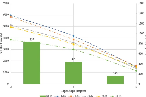
right vertical axis represents the standard deviation of different surface roughness. The following observations can be drawn regardless of the compression force: it can be observed that pull-out force decreases in wider taper angles and the effect of surface roughness on pull out force was much higher in tighter taper angles.
To be more specific, in 2° taper angle, standard deviation of different surface roughness are 275 and 837 in 1500N and 2500N compression force respectively. This relatively high standard deviation indicates significant effect of surface roughness on pull out force in tightest taper angle. In 6° taper angle standard deviation of different surface roughness were 39 and 163 in 1500N and 2500N compression force respectively. This relatively low standard deviation indicated the negligible effect of surface roughness on pull-out force in widest taper angle. It also appears that higher compression forces intensify the influence of surface roughness on pull out force.
Fig. 6. The effect of taper angle on junction strength with standard deviation at 1500N compression force
Fig. 7. The effect of taper angle on junction strength with standard deviation at 2500N compression force
4 DISCUSSION
There are many factors which affect the junction strength of modular implants. As demonstrated earlier, the design of taper angle and surface roughness significantly influence the pull out force and unintended disassembly [4]. These design features, taper angle and surface roughness play a vital role in defining the strength of the taper when implants were assembled with an identical compression force. Despite of the aforementioned factors there are many variables that affect the junction strength of the modular implant that are under the surgeons` control, including the assembly procedure; whether a push on assembly or dynamic impaction were used, and whether the taper was wet or dry.
4.1 Surface Roughness
Basically, all macroscopic bodies have surfaces with different scales roughness. The difference between rough and smooth surfaces is the difference of hills and valleys of the asperities (bumps), even a smooth and fine surface has microscopic hills and valleys. When two bodies are brought into contact with nominally flat surfaces there is just real (atomic) contact in small randomly distributed areas. Real contact area is very small fraction of the nominal contact area. [29]. Two smooth surfaces can have much more real surface contact than two rough surfaces but the hardness of the surface is also a key factor. If the two contacted surfaces are very hard such that the peaks of the bumps do not get mashed down under the contact force, then the amount of real surface contact may not increase very much. Thus, in this study, smoother surfaces possess more microscopic real contact area than rougher surfaces,
which means that surface roughness 1.06 µm has more real
surface contact compared to surface roughness 4.18 µm.
Hence, higher pull out force is needed to overcome the friction made by contacted surfaces.
The size and distribution of the contact asperities depend on the surface roughness and also the compression force. Even plastic deformation can occur in small scale when the total contact loads are not significant enough to cause macroscopic deformation [22]. Hertzian theory claimed a model where each asperity (bump) consists of microasperities and each microasperities is also covered with micromicroasperities [30]. By increasing the load the real contact areas increase. It means
the real contact area has direct correlation with load (A ∝ P)
164502-7979-IJMME-IJENS © April 2016 IJENS I J E N S
for the sample of 2° taper angle and smoothest surface roughness required approximately 5900N of pull out force, which is practically impossible to generate intraoperatively [32].
4.2 Taper Angle
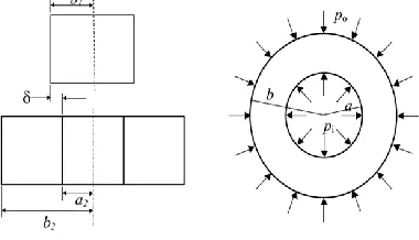
Regarding developing a relation for the contact pressure on taper matting surfaces, principle of calculating the interference conditions of two shafts and hubs is illustrated in Figure 8.
The contact pressure c is calculated by the following
equation:
c= b -b1 cos
b1b (1)
where E is Young’s modulus, is initial interference, is
outer radii of the hub, b1 is outer radii of the shaft and is
taper angle [33]. Thus, the amount of contact pressure c
decrease in wider taper angle due to the smaller amount of cos .
Fig. 8. Interference fit between shaft and hub
The resultant contact force (N) due to the fitting is obtained by
the integration of the contact pressure ( c) over the contact
area along the tapered interface:
= ∫ ccos b1 cd . (2)
where is total length of the contacting interface [34]. The
pressure contact has direct correlation with contact force so by decreasing the contact pressure the contact force also will
reduce. Pull-out force p is equal to:
= (sin -μ cos ). (3)
where µ is coefficient of friction [33]. Consequently by reduction of contact force it needs to less pull-out force is needed. Accordingly, taper angle 6° produce less contact pressure so it requires less pull-out force to reach the turn off moment.
Fig. 9. .Free body diagram during the pull out force p
5 CONCLUSION
The results obtained in this study demonstrate that taper angle and surface roughness affect the pull out force. The main findings of this study can be summarized as follows:
i. The highest pull off force occurred at 2° taper angle
and by increasing the taper angle the pull out force reduced rapidly, i.e. there is lower probability of implant loosening problem in tighter angle compared to wider angle.
ii. The highest pull out force occurred at smoother
surface roughness and gradually declined in rougher areas, thus there is lower probability of implant loosening problem in finer surface roughness compared to rougher area.
Comparing the result illustrated that taper angle change was more influential compared to surface roughness variations, i.e. finding the optimum taper angle should be the first priority in designing the implant. In other words, the problem of implant loosening is more dependent on taper angle changes than surface roughness variations.
ACKNOWLEDGEMENT
The authors would like to acknowledge the financial support from the Ministry of Higher Education Malaysia (MOHE) and
Universiti Teknologi Malaysia (UTM) through the
Fundamental Research Grant and Research University Grant Scheme.
REFERENCES
[1] M. Baxmann, S. Y. Jauch, C. Schilling, W. Blömer, T. M. Grupp, and M. M. Morlock, “The influence of contact conditions and micromotions on the fretting behavior of modular titanium alloy taper connections.,” Med. Eng. Phys., vol. 35, no. 5, pp. 676–83; discussion 676, May 2013.
[2] M. L. Mroczkowski, J. S. Hertzler, S. M. Humphrey, T. Johnson, and . R. Blanchard, “ ffect of impact assembly on the fretting corrosion of modular hip tapers.,” J. Orthop. Res., vol. 24, no. 2, pp. 271–9, Feb. 2006.
[3] J. P. Heiney, S. Battula, G. a Vrabec, A. Parikh, R. Blice, A. J. Schoenfeld, and G. O. jus, “Impact magnitudes applied by surgeons and their importance when applying the femoral head onto the Morse taper for total hip arthroplasty.,” Arch. Orthop. Trauma Surg., vol. 129, no. 6, pp. 793–6, Jun. 2009.
[4] A. T. ennock, A. H. Schmidt, and . a. Bourgeault, “Morse-type tapers,” J. Arthroplasty, vol. 17, no. 6, pp. 773–778, Sep. 2002. [5] William J. Ho ack, “Head-Neck Modularity for Total Hip
Arthroplasty Is It Necessary?,” J. Arthroplasty, vol. 11, no. 4, pp. 397–399, 1996.
164502-7979-IJMME-IJENS © April 2016 IJENS I J E N S [7] W. Brandt, A. Claro Neves, A. P. de Lima, P. C. Feitosa, and L.
Silva- oncílio, “Stability of external and internal implant connections after a fatigue test,” Eur. J. Dent., vol. 7, no. 3, p. 267, 2013.
[8] I. akahara, M. Takao, S. Bandoh, and . Sugano, “ ixation strength of taper connection at head-neck junction in retrieved carbon fiber-reinforced K hip stems.,” J. Artif. Organs, vol. 17, no. 4, pp. 358–63, Dec. 2014.
[9] . Wang, Z. Dai, T. Wen, M. i, and Y. Hu, “Three to seven year follow-up of a tapered modular femoral prosthesis in revision total hip arthroplasty.,” Arch. Orthop. Trauma Surg., vol. 133, no. 2, pp. 275–81, Feb. 2013.
[10] N. Bishop, F. Witt, R. Pourzal, A. Fischer, M. Rütschi, M. Michel, and M. Morlock, “Wear patterns of taper connections in retrieved large diameter metal-on-metal bearings.,” J. Orthop. Res., vol. 31, no. 7, pp. 1116–22, Jul. 2013.
[11] A. J. Smith, P. Dieppe, K. Vernon, M. Porter, and A. W. Blom, “ ailure rates of stemmed metal-on-metal hip replacements: analysis of data from the National Joint Registry of England and Wales.,” Lancet (London, England), vol. 379, no. 9822, pp. 1199– 204, Mar. 2012.
[12] F. Witt, J. Gührs, M. M. Morlock, and N. E. Bishop, “Quantification of the ontact Area at the Head-Stem Taper Interface of Modular Hip rostheses.,” PLoS One, vol. 10, no. 8, p. e0135517, Jan. 2015.
[13] Y.-S. Yoon, T. R. Oxland, A. J. Hodgson, C. P. Duncan, B. a Masri, and D. hoi, “Mechanical aspects of degree of cement bonding and implant wedge effect.,” Clin. Biomech. (Bristol, Avon), vol. 23, no. 9, pp. 1141–7, Nov. 2008.
[14] R. B. Cook, B. Sci, B. J. R. F. Bolland, F. Tr, J. A. Wharton, S. Tilley, J. M. atham, . Orth, and R. J. K. Wood, “ seudotumour Formation Due to Tribocorrosion at the Taper Interface of Large Diameter Metal on olymer Modular Total Hip Replacements,” vol. 28, pp. 1430–1436, 2013.
[15] A. Rehmer, N. E. Bishop, and M. M. Morlock, “Influence of assembly procedure and material combination on the strength of the taper connection at the head-neck junction of modular hip endoprostheses.,” Clin. Biomech. (Bristol, Avon), vol. 27, no. 1, pp. 77–83, Jan. 2012.
[16] E. Pansard, N. Fouilleron, G. Dereudre, H. Migaud, and J. Girard, “Severe corrosion after malpositioning of a metallic head over the Morse taper of a cementless hip arthroplasty. A case report.,” Orthop. Traumatol. Surg. Res., vol. 98, no. 2, pp. 247–50, Apr. 2012.
[17] C. Mangano, F. Mangano, J. a. Shibli, L. Tettamanti, M. Figliuzzi, S. d’Avila, R. . Sammons, and A. iattelli, “ rospective valuation of 2,549 Morse Taper Connection Implants: 1- to 6-Year Data,” J. Periodontol., vol. 82, no. 1, pp. 52–61, Jan. 2011.
[18] . Hernigou, S. Queinnec, and . H. lou at achaniette, “One hundred and fifty years of history of the Morse taper: from Stephen A. Morse in 1864 to complications related to modularity in hip arthroplasty.,” Int. Orthop., vol. 37, no. 10, pp. 2081–8, Oct. 2013. [19] . Sancaktar and R. Gomatam, “A study on the effects of surface
roughness on the strength of single lap joints,” J. Adhes. Sci. Technol., vol. 15, no. 1, pp. 97–117, Jan. 2001.
[20] T. ekerc O lu, H. Rende, A. G ls , and . Meran, “The effects of surface roughness on the strength of adhesively bonded cylindrical components,” J. Mater. Process. Technol., vol. 142, no. 1, pp. 82– 86, Nov. 2003.
[21] S. Gravius, D. C. Wirtz, C. H. Siebert, S. Andereya, R. Mueller-Rath, U. Maus, and T. Mumme, “In vitro interface and cement mantle analysis of different femur stem designs.,” J. Biomech., vol. 41, no. 9, pp. 2021–8, Jan. 2008.
[22] J.-J. Ryu, V. Dayal, and . Shrotriya, “Onset of Surface Damage in Modular Orthopedic Implants: Influence of Normal Contact Loading and Stress-assisted Dissolution,” Exp. Mech., vol. 47, no. 3, pp. 395–403, Feb. 2007.
[23] U. J. Schlegel, S. Rothstock, J. Siewe, K. H. Schiwy-Bochat, P. ysel, and M. M. Morlock, “Does impaction matter in hip resurfacing? A cadaveric study.,” J. Arthroplasty, vol. 26, no. 2, pp. 296–302, Feb. 2011.
[24] E. Bressan, D. Lops, C. Tomasi, S. Ricci, M. Stocchero, and E. L. arniel, “ xperimental and computational investigation of Morse taper conometric system reliability for the definition of fixed connections between dental implants and prostheses.,” Proc. Inst. Mech. Eng. H., vol. 228, no. 7, pp. 674–81, Jul. 2014.
[25] S. Y. Jauch, G. Huber, E. Hoenig, M. Baxmann, T. M. Grupp, and M. M. Morlock, “Influence of material coupling and assembly condition on the magnitude of micromotion at the stem-neck interface of a modular hip endoprosthesis.,” J. Biomech., vol. 44, no. 9, pp. 1747–51, Jun. 2011.
[26] B. Weisse, C. Affolter, a Stutz, G. P. Terrasi, S. Köbel, and W. Weber, “Influence of contaminants in the stem–ball interface on the static fracture load of ceramic hip joint ball heads,” Proc. Inst. Mech. Eng. Part H J. Eng. Med., vol. 222, no. 5, pp. 829–835, May 2008. [27] J. Gührs, A. Krull, . Witt, and M. M. Morlock, “The influence of
stem taper re-use upon the failure load of ceramic heads.,” Med. Eng. Phys., vol. 37, no. 6, pp. 545–52, Jun. 2015.
[28] I.-S. Park, K.-S. Lee, G.-S. Shin, S.-K. Lyu, M.-H. Lee, and T.-S. Bae, “Mechanical properties of Ti-6Al-4V alloy mini-implant system,” Int. J. Precis. Eng. Manuf., vol. 14, no. 9, pp. 1601–1605, Sep. 2013.
[29] B. N. J. Persson, O. Albohr, U. Tartaglino, a I. Volokitin, and E. Tosatti, “On the nature of surface roughness with application to contact mechanics, sealing, rubber friction and adhesion.,” J. Phys. Condens. Matter, vol. 17, no. 1, pp. R1–R62, Jan. 2005.
[30] J. a. Greenwood and J. B. . Williamson, “ ontact of ominally lat Surfaces,” Proc. R. Soc. A Math. Phys. Eng. Sci., vol. 295, no. 1442, pp. 300–319, Dec. 1966.
[31] M. . Rapetto, a. Almqvist, R. arsson, and . M. ugt, “On the influence of surface roughness on real area of contact in normal, dry, friction free, rough contact by using a neural network,” Wear, vol. 266, no. 5–6, pp. 592–595, Mar. 2009.
[32] S. H. aidu and A. Radin, “Modular ulnar head decoupling strength: a biomechanical study.,” J. Hand Surg. Am., vol. 34, no. 10, pp. 1845–50, Dec. 2009.
[33] D. B. and S. M ft , “Mechanics of the tapered interference fit in dental implants,” J. Biomech., no. 617, pp. 1–27, 2002.