(Full length research article)
Design and Optimization of Silo using FEM
Ramakrishna Vemulaa* and K. Venkateswararaoa
aDepartment of Mechanical Engineering, Sir C.R.R.College of Engineering, Eluru-534007, West Godavari Distt. A. P.
Received 27 June 2012; accepted 29 June 2012, Available online 30 June 2012
Abstract
Circular cylindrical silo structures are prone to cross-sectional distortion (ovalisation), when subjected to pressure and wind loading. This ovalisation is resisted by the ring beam at the junction of intersection of silo wall and its supporting tower as well as in plane rigidity of the silo roof .This paper deals with such phenomenon using a finite element model in Ansys. A case study has been carried out using the pressure and wind load distribution as per relevant IS code of practice Results obtained from the three dimensional finite element model of the silo clearly support the fact of transverse bending of the silo wall, which was empirically supported by the analytical model. It also shows that the values obtained thus are much on lower end compared to the results of analytical model in bending of silo wall in transverse direction, whereas it also evaluates longitudinal stresses, which are equally significant Also the effect of cross-sectional distortion of the silo wall, i.e., the ovalisation is found to be critical only at middle one-half height of the silo wall.
Keywords: Silo, Design, Optimization, FEM
1. Introduction
1
Silos are widely used in a great many different industries for storing a huge range of different solids. The sizes of these silos may vary from capacities less that 1 tone to the largest containing as much as 100 000 tones. The size of the silo has a strong bearing on the number of different considerations required: small silos generally do not produce structural problems, but in large silos many different aspects need careful attention [1].
The designs used for silos also vary very much. In some industries (e.g. grain storage), there is a competitive industry producing standard silo products which function extremely well and cost-effectively provided the conditions remain those anticipated. In other industries (e.g. cement and mineral ore storage) very large silos are used and every silo must be individually designed for the special conditions. It should be noted that each silo is normally designed to contain a very limited range of solids, and that the use of a silo designed for one kind of solid to store different solids can easily cause damage. Bulk solids vary very much in their properties, and a silo
*Ramakrishna Vemula is a PG student and K. Venkateswararo is working as Associate Prof. in Department of Mechanical Engineering, Sir C.R.R.College of Engineering, Eluru-534007, West Godavari Distt. A. P., Corresponding author’s email: vrkmejpt@gmail.com
that is perfectly adequate to store one material may be very dangerous for another [2].
The terms silo, bunker, bin and hopper are often used to refer to similar containers in different industries. Here, the word ‘hopper’ is exclusively used with a special meaning for the converging part leading to a gravity discharge outlet. All complete storage containers are referred to as silos, irrespective of the stored solid, geometry and industrial sector. A characteristic form to describe the parts of the silo is shown in Figure 1. The transition, which lies at the junction between the vertical wall and the hopper, should be noted [3]
This chapter provides a brief outline of the development of understanding of pressures that develop in silos and their consequences for the safety of the silo structure. More structural failures occur in silos than in any other engineered structural form, considering the numbers of each, and these failures occur in all countries and all industries. Structural design considerations for silos are therefore a key aspect of bulk solids handling systems [4].
2. Modeling of silo structure
Modeling of silo is done in Pro-E, a 3D modeling package. The geometric details of the silo considered in this thesis are as follows.
International Journal of Engineering, Science and Metallurgy
A 2000 tons capacity cement storage silo supported on 6 no’s columns (Figure 1) has been considered. The column heads are connected with a ring beam at level (+) 12.0m, which is supporting the entire silo volume together with the conical hopper supporting the material. The silo wall thickness has been assumed as 200 mm and the other relevant-general arrangements have been shown in Fig 5.1. The main objective of this study is to evaluate the deformation of 30.0 m high silo wall when subjected to wind load and infer about the necessary steps to be taken up by the designers practicing professionals. It's important to note that the height of silo wall to diameter ratio is very close to 2.0 and hence may be considered as long [5-6].
Fig. 1Terminology for parts of a typical silo
Fig.2 Silo structure designed in Pro-E
It is connected to the ring beam. So at the ends, the wall may well be assumed as rigidly connected, leading thereby deformation to its minimum. The bottom of the wall has been considered as fixed to the ring beam as it provides a good rigidity to arrest lateral sway of the combined. Although the topmost level is free to deflect, due to in plane rigidity and diaphragm action of the roof slab the total deflection is also minimized. If the end/support conditions are properly simulated with above knowledge in the mathematical model, one can readily understand that the maximum deformation takes place at a level close to the topmost level. The extent of this deformation of silo wall, i.e., ovalisation effect increases as the ratio of HID of silo increases beyond 2. In all cases the transverse shear due to wind load has been assessed following the method laid down by relevant IS code of practice, applicable to such Silo Structures. To derive the response of silo wall subjected to wind load, an annular ring of height unity has been considered and the same has been taken at the level between (+) 10.0m to 15 m. The horizontal load on such ring due to wind is calculated based on wind pressure distribution as per IS 875 Part – III[20] [7-12].
3. Material properties
Table.1 Material properties considered for silo
Material used Youngs Yield Poisions Density
modulus strength ratio (Kg/m3)
(GPa) (MPa)
Steel 210 550 0.266 7860
Concrete
reinforcement 250 300 0.17 2400
4. Results & discussion
4.1 Static Analysis
Static comparison between Steel and Reinforced Concrete Silo Structure are shown below with the help of Radial stress, Tangential stress, longitudinal stress, Von Misses stress, deflection plots and their comparative graphs are displayed along with the stress plots [13].
Silo storage Structure is shown in Figure .4 shows Von Misses Stress value levels according to the load and stricture, color bar is used to indicate the value range on model. Von-Misses stress depends on the von-misses theory of failure.
Fig. 3 Von Misses Stress 200 thick of Concrete Reinforcement
Fig. 4 Von Misses Stress 200 thick Steel
Fig. 5 Von Misses Stress 110 thick of Steel
Silo storage Structure is shown in Figure 5 shows Von Misses Stress value levels according to the load and stricture, color bar is used to indicate the value range on model. Von-Misses stress depends on the von-misses theory of failure [15].
4.2 Modal Analysis of Silo Structure
The goal of modal analysis in structural mechanics is to determine the natural mode shapes and frequencies of an object or structure during free vibration. It is common to use the finite element method (FEM) to perform this analysis because, like other calculations using the FEM, the object being analyzed can have arbitrary shape and the results of the calculations are acceptable [16]. The types of equations which arise from modal analysis are those seen in Eigen systems. The physical interpretation of the Eigen values and eigenvectors which come from solving the system are that they represent the frequencies and corresponding mode shapes. Sometimes, the only desired modes are the lowest frequencies because they can be the most prominent modes at which the object will vibrate, dominating all the higher frequency modes. It is also possible to test a physical object to determine its natural frequencies and mode shapes. This is called an Experimental Modal Analysis. The results of the physical test can be used to calibrate a finite element model to determine if the underlying assumptions made were correct (for example, correct material properties and boundary conditions were used) [17].
Here modal analysis is done for finding the natural frequencies, and how they vary under different conditions. The following figures represent the first six mode shapes of the Silo Structure of both Steel and concrete reinforcement [18].
4.2.1 Mode shapes of Steel structure with 200thick
Fig.6 (b) Second mode shape
Fig.6 (c) Third mode shape
Fig.6 (d) Fourth mode shape
Fig.6 (e) Fifth mode shape
The above plots represent the first five mode shapes of Silo storage Structure. These values consider as natural frequency.
4.2.3 Mode shapes of Steel structure with 110thick.
Fig.7 (a) First mode shape
Fig.7 (c) Third mode shape
Fig.7 (d) Fourth mode shape
Fig.7 (e) Fifth mode shape
The above plots represent the first five mode shapes of Silo storage Structure. These values consider as natural frequency.
4.3 Harmonic analysis.
Commonly harmonic analysis is used to test the geometry under harmonic loads and also for the earth quack conditions.
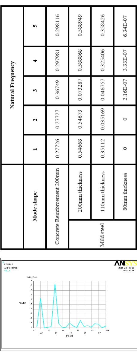
4.3.1 Harmonic results for concrete.
Table 2 Modal Analysis summary
4.3.2. Harmonic results for steel 200thick.
Fig.9 Middle of the Storage tank
4.3.3. Harmonic results for steel 110thk.
Fig.10 Middle of the Storage tank
4.3.4. Harmonic results for steel 80thick.
Fig.11 Middle of the Storage tank
The above graphs show displacement with the combination of frequency levels.
Table 3 Harmonic Analysis summary
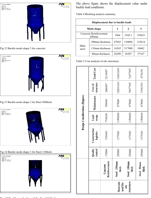
4.4. Buckling analysis of Silo Structure
Fig.12 Buckle mode shape 3 for concrete
Fig.13 Buckle mode shape 3 for Steel 200thick
Fig.14 Buckle mode shape 3 for Steel 110thick
Fig.15 Buckle mode shape 3 for Steel 80thick
The above figure shows the displacement value under buckle load conditions.
Table 4 Buckling analysis summary
Displacement due to buckle loads
Mode shape 1 2 3
Concrete Reinforcement
200mm 1964 3545.1 3560.9
Mild steel
200mm thickness 67043 120806 122614
110mm thickness 16265 317088 36062
80mm thickness 26290 26387 37167
6. Conclusion
Detailed three-dimensional numerical simulation on Steel and Concrete Reinforcement silo structure were carried out. Large internal loads were applied for static, modal, harmonic and for buckle analysis the structure is loaded internally and externally. The following conclusions can be made from this work.
1. The results revealed that in the case of static analysis the stress values varied when the thickness of wall is modified form 200mm to 110mm& 80mm.
2. Modal analysis shows the safety of the structure as the steel and concrete reinforcement structure easily undergoes the heavy loads applied on it, thereby giving uniform incremental Natural Frequencies
3. With the help buckling simulations carried on the on steel and concrete reinforcement silo structure we came to encounter that the structure may fail at the center region of legs.
4. The cost estimated to build silo structure designed in the report for steel is 6756350 Rupees, concrete reinforcement is 12338087 Rupees.
5. Here with the help of the complete study carried out in this project we came to know that the concrete reinforcement structure does compete with the steel structure in all aspects in a positive. This leads us to compare the Design Considerations.
References
1. T J Kwun, E Kyo, M H Jang and I N Kwun, Mechanical Behaviour of Cantilevered Cylindrical Shell in Opening under Lateral Load, Transactions of the 15th International Conference on Structural Mechanics in Reactor Technology (SMRT – 15), Seoul, Korea.
2. J G A Croll (2006), Design Analysis for Buckling of Tank and Silos, Journal of Structural Engineering, vol 132, no 1, ASCE, p 43.
3. M T Abdel-Fattah, I D Moore and T T Abdel-Fattah (2006), A Numerical Investigation into the Behaviour of Ground-supported Concrete Silos Filled with Saturated Solids, International Journal of Solids and Structures, vol 43, no 13, p 3723.
4. Y Uematsu and K Uchiyama (1985) , Deflection and Buckling Behaviour of Thin, Circular Cylindrical Shells under Wind-loads, J. Wind Engg: and Industrial Aerodynamics, vol 18, p 245.
5. J M Rotter and T S Hull (1989) , Wall Loads in Squat Steel Silos During Earthquakes, Engineering Structures,
vol 11, no 3, p 139.
6. R Greiner and P Derler (1995), Effect of Imperfections on Wind-loaded Cylindrical Shells, Thin-Walled Structures, vol 23, no 1-4, p271.
7. H Schmidt, B Binder and H Lange (1998), Post Buckling Strength Design of Open Thin-walled Cylindrical Tanks under Wind Load, Thin-Walled Structures, vol 31, p 203. 8. G Portela and L A Godoy (2005), Wind Pressure and
Buckling of Cylindrical Steel Tanks with a Dome Roof, Journal of Constructional Steel Research, vol 61, no 6, p 808.
9. G Portela and L A Godboy (2005) , Wind Pressures and Buckling of Cylindrical Steel Tanks with a Conical Roof,
Journal of Constructional Steel Research, vol 61, no 6, p 786.
10. S S Safarian and E C Harris (1985), Design and Construction of Silo and Bunkers, Van Nostrand Reinhold Company Inc., USA,p 290.
11. Y Uematsu, K Uchiyama, M Yamada and S Sanjyo (1998), Ovalling Oscillations of Thin Circular Cylindrical Shells in a Cross Flow, Journal of Fluids and Structures, vol 2, no 3, p 285.
12. S A Karamanos (2002), Bending Instabilities of Elastic Tubes, International Journal of Solids and Structures, vol 39, no 8, p 2059.
13. A K Samanta and P Datta (2000), A Case Study of Assessment of the Effect of Bending and Transverse Shear on, Right Circular Cylindrical Structures, Journal of The Institution of Engineering(I); vol 86, p 34.
14. T Fuat and F Bazman ,Stiffening of Thin Cylindrical Silo Shell againt Buckling Load, International Conference on Machine Design and Production, Kusadasi, Turkey. 15. D Dooms, G Degrande, G D Roeck and E Reynders (2006)
,Finite Element Modelling of a Silo based on Experimental Modal Analysis, Engineering Structures, vol 28, no 4, p 532.
16. R C Jaca, L A Godoy, F G Flores and J G A Croll (2007) , A Reduced Stiffness Approach for the Buckling of Open Cylindrical Tanks under Wind Loads, Thin-walled Structures, vol 45, no 9, p 727.
17. A Dogangun, Z Karaca, A Durmus and H Sezen (2009) , Cause of Damage and Failures in Silo Structures, Journal of Performance of Constructed Facilities, ASCE, vol 23, no 2,p 65.