Path Selection and Effects of Channel
Behaviour in Multicast Networks
Shivani Kukreja1 and Dr. Parminder Singh2
I. INTRODUCTION
Mobile ad-hoc networks is an assemblage of multiple mobile nodes which are connected wirelessly to one another without any predefined infrastructure. Some of the unique properties of MANET are that they are self-organizing, self-healing and self-forming. Such a versatile behavior makes them one of fast emerging technology which have brought revolution in the wireless network era.
There are various independent nodes which are free to move within the network. As the nodes are independent so each node is free to move independently in any direction as the result the links are not certain and these links changes frequently. Such networks may work independently or can be connected to other larger network with single or multiple transrecievers between the nodes. Another diversified feature of MANET is that they can be integrated with other heterogeneous networks such as WiMAX and cellular networks.
The major concern is toward the routing as the nodes and their links are not supposed to be fixed. Various routing protocols are classified under three main categories i.e. reactive routing protocols which are table driven and usually maintain a routing table from source to destination, these includes OLSR, DSDV etc. Other is proactive protocols that are usually on demand routing these include AODV, DSR etc. Or Hybrid routing protocols such as ZRP that have the mixed properties of reactive and proactive routing protocols. In MANETs nodes can act both as routers and the hosts themselves which makes them dynamic in nature.
1 Department of IT, Chandigarh Engineering College, Landran Mohali, India 2 Department of IT, Chandigarh Engineering College, Landran Mohali, India
e-ISSN:2278-621X
Abstract: This paper gives short introduction to mobile ad-hoc networks which have gained so much of
acceptance in world of wireless networks and helped the technology to move to a next level. With the numerous benefits of mobile ad-hoc networks from disaster relief operations to urgent business meetings, there comes few parameters such as bit error rate, queue delay and throughput that hinder their performance. Various approaches that help in improving the performance of the multicast networks have been described throughout. The path selection concept effects the above stated quality parameters. Also the factors such as traffic load and transmission capacity can be taken into consideration for bringing out the quality results from mobile ad-hoc networks. Various simulation experiments have been carried out to show the improvement in the performances comparing it to the previous approaches. The results have been compared to reflect the performance up gradation once after the algorithm has been applied.
Keywords- WMN, MANET, OLSR, AODV, JRS- Joint Routing and Scheduling, BS, BER, DTA, BPSK
Most of the nodes of a MANET are battery operated so energy conservation and power management becomes an important issue of concern for the network operation. Generally the power is turned off when these nodes are not in use. The transmission power usually varies with the two factors that are the communication needs and the battery levels. The ultimate target is to communicate with efficient battery power and efficient transmission rates which merely depends upon the location of the nodes which are deployed randomly as the location of the network is dynamic
The figure 1 illustrates a simple MANET 802.11 framework with an assortment of laptops and PDA’s forming a “self-organizing” and “self-configuring” network with no underlying infrastructure.
Figure 1: Mobile Ad-hoc Networks (MANETs) [4]
II. PRESENT WORK
In MANETS the nodes are connected to one another in a self-configuring manner. The major issue of concern that draw the attention is that although these network has variable capacity links but there is bandwidth constraint. In order to improve the performance of the underlying network scenario is the deployment of the Omni-directional antennas between the existing source to destination nodes can be the solution. When there is one to one link between the nodes and the bandwidth is constrained but with the implementation of the omni-directional antennas we extend the performance as the bandwidth is increased to multiple times as the result the transmission rates can be improved.
Interference issues have been studied extensively recently because it is widely believed that reducing the interference can increase the overall performance of a wireless network. There are different approaches to reducing the interference, including scheduling on the MAC layer, route selection on the routing layer, and power control on the physical layer.
For WMNs, the aggregate traffic load of each routing node changes infrequently also unique characteristic of wireless networks is that the radio sent out by a wireless terminal will be received by all the terminals within its transmission range and also possibly cause signal interference to some terminals that are not intended receivers
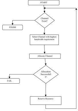
2.1 Methodology Used
The above flowchart illustrates of flow chart for the resource reservation. The figure depicts the channel assignment with the highest bandwidth requirement and channel allocation is done in such a way that all the bandwidth requirement is fulfiled with the available time slots. Once the channel is allocated the flow of packets from source to destination starts.
needs to be determined. The MBS estimates the uplink and downlink traffic ratio and divides the data sub-frame of the mesh sub-frame into a proportionate number of uplink and downlink.
III. EXPERIMENTAL SETUP
The scenario has a size of 700 × 800 meters, which is the average coverage provided by an AP using the standard 802.11 .The transmitter is created using the ‘simple_source’ module included in OPNET’s libraries. The traffic source creates packets with an inter arrival time of 1 packet per second and a constant length of 1024 bits.
Figure 2: Experimental Setup START
Select Channel with highest bandwidth requirement
Allocate Channel
Reserve Resource FINISH
FAIL
Channel Exist?
Allocation Successfull
Each node communicates to its neighbor node and ICMP protocol has generated the routing table and the best route path selection considered by the every source of the network.
Table 1: Routing Table
Destination
M etr ic
Next Hop
Address Next Hop Node
Outgoin g
Interface
Insertion Time (secs) 192.0.1.0/24 3 192.1.100.1 subnet_0.node_3 IF0 73.626 192.0.2.0/24 2 192.1.100.1 subnet_0.node_3 IF0 73.626 192.0.4.0/24 4 192.1.100.1 subnet_0.node_3 IF0 73.626 192.0.140.0/24 10 192.1.100.1 subnet_0.node_3 IF0 73.626 192.0.145.0/24 9 192.1.100.1 subnet_0.node_3 IF0 73.626 192.0.159.0/24 11 192.1.101.1 subnet_0.node_17 IF1 63.626 192.0.166.0/24 8 192.1.101.1 subnet_0.node_17 IF1 63.626 192.0.186.0/24 12 192.1.101.1 subnet_0.node_17 IF1 63.626 192.0.191.0/24 13 192.1.101.1 subnet_0.node_17 IF1 63.626 192.0.192.0/24 14 192.1.101.1 subnet_0.node_17 IF1 63.626 192.0.210.0/24 16 192.1.101.1 subnet_0.node_17 IF1 63.626 192.0.211.0/24 17 192.1.101.1 subnet_0.node_17 IF1 63.626 192.0.217.0/24 15 192.1.101.1 subnet_0.node_17 IF1 63.626 192.0.235.0/24 11 192.1.101.1 subnet_0.node_17 IF1 63.626 192.0.236.0/24 13 192.1.101.1 subnet_0.node_17 IF1 73.626 192.0.237.0/24 14 192.1.101.1 subnet_0.node_17 IF1 63.626 192.0.238.0/24 14 192.1.101.1 subnet_0.node_17 IF1 63.626 192.0.239.0/24 12 192.1.101.1 subnet_0.node_17 IF1 63.626 192.0.240.0/24 13 192.1.101.1 subnet_0.node_17 IF1 63.626
IV. RESULTS AND DISCUSSIONS 4.1 Previous Approach
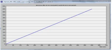
4.1.1 Bit Error Rate (BER)
Bit Error Rate is referred as the rate of error observed while transmission of packets from the source to destination nodes. When running a simulator, BER expects to receive the same pattern that it is transmitting. If traffic is not being transmitted or received, create a back-to-back loopback BER on the link or in the network, and send out a predictable stream to ensure that you receive the same data that was transmitted.
4.1.2 Queue Delay
Queuing Delay is the time that a packet has to wait in the queue before it can be transmitted over the link. Packets are put in the queue when the speed of incoming link to the router is faster than the outgoing link. Queuing delay depends on the number of earlier arrived packets already waiting for getting transmitted.
Figure 4: Queue Delay (sec)
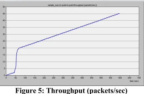
4.1.3 Throughput
It indicates the maximum amount of data that can pass from one point to another in a unit of time. The more devices using the same wireless devices equates to more aggregate traffic utilizing the finite amount of available bandwidth resulting in slower throughput for all connected devices.
Figure 5: Throughput (packets/sec)
4.2 PROPOSED APPROACH
5.2.1 Bit Error Rate (BER)
Figure 6: Proposed Bit Error Rate (BER)
4.2.2 Queue Delay
It indicates the time the packet spends in routing queues. As a queue begins to fill up due to traffic arriving faster than it can be processed, the amount of delay a particular packet experiences traversing the queue increases. The speed at which the contents of a queue can be processed is a function of the transmission rate of the facility. This leads to the "delay curve," depicted in the image to the right. It should maintain the traffic load which equals to the transmission capacity.
.
Figure 7: Proposed Queue Delay (sec)
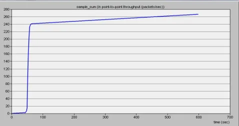
4.2.3 Throughput
Throughput can achieve is the chunk size (amount of data sent per window) divided by the round trip time or Max Throughput = chunk size / RTT Max Throughput in bps = [Bytes * 8 (bits/byte)] / RTT
V. CONCLUSION
In this paper an effort has been made in order to improve the network performance by an effective channel allocation scheme. We have studied various performance metrics of a mobile ad-hoc network such as Bit Error Rate, Throughput, Queue Delay before and after deploying link scheduling algorithm. Based on the stimulation analysis we have obtained significant results of performance up-gradation which have been concluded below:
Table 2: Comparison of Throughput Throughput (packet e
second)
Minimum Average Maximum
Previous Implementation 2 25 42
Proposed Implementation 5 27 47
Table 3: Comparison of Queue Delay
Queue Delay(seconds) Minimum Average Maximum
Previous Implementation 0.00016 0.00020 0.00023 Proposed Implementation 0.00010 0.00012 0.00016
Table 4: Comparison of BER
BER (error per packet) Minimum Average Maximum
Previous Implementation 0.15 0.21 0.27
Proposed Implementation 0.10 0.12 0.15
The above tables concludes the comparison between the previous and the proposed implementations in minimum, average and the maximum case scenarios with the improved results despite of the unpredictable behavior of the wireless mesh networks.
REFERENCES
[1] Sujie Chen,Roger S. Cheng,"Clustering for Interference Alignment in Multiuser Interference Network ",IEEE TRANSACTIONS ON VEHICULAR TECHNOLOGY, VOL. 63, NO. 6, JULY 2014, pp. 2613-2624, 2014.
[2] R. Draves, J. Padhye, and B. Zill, ‘‘Routing in Multi-Radio Multi-Hop Wireless Mesh Networks,’’ Proceedings of ACMMobiCom2004, pp. 114–128, September– October 2004.
[4] Anand Subramanian, Rupa Krishnan, Samir Das, Himanshu Gupta, “Minimum Interference Channel Assignment in Multi-Radio Wireless Mesh Networks,’’ Poster Session at ICNP, International Conference on Network Protocols, 2005.
[5] Arindam K. Das, Hamed M.K. Alazemi, Rajiv Vijayakumar, Sumit Roy, “Optimization Models for Fixed Channel Assignment in Wireless Mesh Networks with Multiple Radios,’’ Proceedings of Second Annual IEEE Communications Society Conference on Sensor and Ad Hoc Communications and Networks, 2005.
[6] Zhao, Q. and Sadler, B. (2007), ‘‘Dynamic spectrum access: signal process, networking, and regulatory policy’’, IEEE Signal Processing Magazine, Vol. 24 No. 3, pp. 78-89, 2007.
[7] J. Tang, G. Xue, W. Zhang. ‘‘Interference Aware Topology Control and Qos Routing in Multi-Channel Wireless Mesh Networks,’’ Proceedings of ACM Mobihoc, 2005.
[8] J. Jang, K. B. Lee, “Transmit power adaptation for multiuser OFDM systems,” IEEE Journal Sel. Areas. Commun., vol. 21, no. 2, pp. 171- 178, Feb. 2003.
[9] Z. Shen, J. G. Andrews, and B. L. Evans, “Adaptive resource allocation in multiuser OFDM systems with proportional rate constraints,” IEEE Trans. Wireless Commun., vol. 4, no. 6, pp. 2726-2737, Nov. 2005.
[10] G. Bianchi, “Performance analysis of the IEEE 802.11 distributed coordination function,” IEEE J. Sel. Areas Commun., vol. 18, no. 3, pp. 535–547, Mar. 2000.
[11] Y. Cheng, X. Ling,W. Song, L. X. Cai,W. Zhuang, and X. Shen, “A crosslayer approach for WLAN voice capacity planning,” IEEE J. Sel. Areas Commun., vol. 25, no. 4, pp. 678–688, May 2007. [12] D. Bertsekas and R. Gallenger, Data Networks, 2nd ed. Englewood Cliffs, NJ: Prentice-Hall, 1992. [13] J. Li, C. Blake, D. S. J. De Couto, H. I. Lee, and R. Morris, “Capacity of ad hoc wireless networks,”
in Proc. ACM MobiCom, pp. 61–69, 2001.
[14] P. C. Ng and S. C. Liew, “Throughput analysis of IEEE 802.11 multihop ad hoc networks,” IEEE/ACM Trans. Netw., vol. 15, no. 2, pp. 309–322, Apr. 2007.