Shearlet Transform Based Satellite Image
Denoising Using Optimized Otsu Threshold
Anju T S
PG Scholar, Electronics and Communication Engineering,
Sree Chitra Thirunal College of Engineering, Trivandrum, Kerala
Mr. Nelwin Raj N R
Asst. professor, Electronics and Communication Engineering, Sree Chitra Thirunal College of Engineering, Trivandrum, Kerala
Abstract- Satellite images have become universal standard in almost all applications of image processing. However, satellite images are mostly degraded due to the inaccuracy or limitations of the transmission and storage devices. Development of a denoising algorithm in satellite images is still a challenging task for many researchers. Most of the state of the art denoising schemes employ wavelet transform but the main limitation of wavelet transform is it can capture only limited information along different directions. Hence edges in an image get distorted.Shearlet transformation is a sparse, multiscale and multidimensional alternative to wavelet transform. Shearlet transform is optimal in representing image containing edges. In this paper, a novel image denoising algorithm utilizing shearlet transform and Otsu thresholding is presented which was found to exhibit superior performance among other state of the art image denoising algorithms in terms of peak signal to noise ratio (PSNR) and visual quality.
Keywords – Denoising, Discrete Shearlet Transform, Otsu Thresholding, Artificial Bee Colony (ABC) optimization.
I. INTRODUCTION
In modern era, satellite images have a plethora of applications particularly in the fields of oceanographic studies, weather forecasting, agriculture and forestry, intelligence and planning etc. The high frequency components, or the edges, present in those images constitute the vital piece of information. Unfortunately, due to the lacking image acquisition and transmission systems, the images get deteriorated with noise. So there arose an overwhelming need to develop a denoising algorithm for the elimination of noise from degraded satellite images. Researchers developed wide variety of denoising systems for satellite images. But the development of an effective denoising method keeping an eye on the preservation of fine details is still a challenging task.
analysis, curvelets are replaced by contourlets. Authors in [3] introduced contourlet transform which can capture intrinsic geometrical features of the image compared to curvelets. But the main limitation is that they have limited directional sensitivity compared to that of curvelets. From all of the above techniques, we see that conventional image denoising algorithms distorts edges in the image due to lack of directional sensitivity and multiresolution analysis. In [4], authors introduced shearlet transform which provides sparse representation of multi-dimensional data. They have well localized waveforms and high directional sensitivity compared to other state-of-art techniques. They are associated with multiscale and multidirectional decomposition, which enable them to capture intrinsic geometric features of image. The proposed method using shearlet transform can be applied to different satellite images. From the experimental analysis, it was found that the proposed method exhibit better peak signal-to-noise ratio (PSNR) and visual quality compared to conventional image denoising algorithms.
The paper is organized as follows. Section II gives an overview of Discrete Shearlet Transform. Section III intro- duces the proposed image denoising via optimal Otsu threshold selection using artificial bee colony optimization. Section IV gives the results and discussions of the proposed method with other existing methods. Conclusions are given in the final section.
II. DISCRETE SHEARLET TRANSFORM
Shearlet Transform combines multiscale and multi-directional representation and is very efficient to capture intrinsic geometry of the multidimensional image and is optimally sparse in representing image containing edges [4]. The shearlet decomposition procedure is initiated by separating the image into its high pass and low pass components, which is accomplished using Laplacian pyramid [5]. The Discrete Fourier Transform of the high pass component is then calculated on a pseudo-polar grid and is then applied to a bandpass filter. The image is then reconstructed by applying the inverse pseudo-polar grid and restoring directly the Cartesian sampled values. The shearlet decomposition of the image is shown in Figure 1.
For a two dimensional image, the basis function of the shearlet transform is given by,
ADS (ψ) = {ψ
j,k,l(x) = |det(D)|
j/2ψ(S
lD
jx –k) : j, l ϵ Z , k ϵ Z
2}
(1)Where ψ ϵ L2(R2), D and S are 2×2 invertible matrices and det(B) = 1. Here Dj represents the dilation matrix and Sl represent the shearing matrix. From equation (1) we see that basis functions are not only limited to translation and scaling but also shearing along various orientations.
If Ƒ = {ψ j,k,l(x): j, l ϵ Z , k ϵ Z2}represents shearlet basis function such that every image can be represented using Ƒ, then the approximation function is given by,
ƑN =
Ʃ
<
Ƒ,ψ
j,k,l(x)
>
ψ
j,k,l(x)
(2)The N-term approximation error which describes how well an image can be approximated by using a set of basis function is given by,
ԑ
N = || Ƒ - ƑN || =Ʃ
|
<
Ƒ,ψ
j,k,l(x)
>
|
2 (3)As the value of N-term approximation decreases, we can say that algebraic sum of basis function is very close to that of original image. The N-term of approximation error of shearlet is given by,
ԑ
N ≤ CN-2 (log N)3 (4)which is optimal compared to that of wavelets (CN-1) and Fourier transform (CN-1/2).
III. THE PROPOSED METHOD
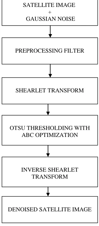
The block diagram of the shearlet transform based satellite image denoising is shown in Figure 2. The main steps involved in the denoising algorithm are summarized as follows:
1) Initially, gaussian noise is added to original image with zero mean and variance σ2 2) The noisy image is applied to a preprocessing filter; median filter is used in this method
3) Using Discrete Shearlet Transform, decompose the image into four levels and at each level of decomposition few subband images are generated
4) For each subband, compute the Otsu threshold which is optimized using artificial bee colony algorithm. The threshold is applied to the noisy shearlet coefficients to get denoised coefficients
5) Apply Inverse Discrete Shearlet Transform to modified coefficients to get the denoised image
Shearlet decomposition results in large number of shearlet coefficients and we need to separate noisy coefficients from original ones. Thresholding is very important because thresholding at large values result in loss of information whereas at low values result in background clutter. Let S(x, y) represent the initial shearlet coefficient in the point (x, y) in each sub-band K ϵ { K1 K2 …. Kj}at scale j. The aim of this paper is to obtain denoised coefficient D(x,y) at the point S(x,y) by adjusting the pixel values i.e.,
D(x,y) = S(x,y) if S(x,y) > T
else 0 (5)
1. Otsu Thresholding
The procedure to obtain Otsu threshold T is summarized below [6]: a) Compute normalized histogram
b) Set the threshold T=K and divide f(x,y) into two classes C1 and C2. Probability that f(x,y) is in class C1 is P1(K) and probability that f(x,y) in class C2 is P2(K) = 1-P1(K)
c) Compute cumulative mean of C1 and C2 i.e.,M1 and M2 d) Compute Global mean, MG = P1M1 + P2M2
e) Compute the in-between class variance,
σ
B2
(k) = [MG P1(k) – M(k)] 2
/ P1(k) × P2(k) (6) f) Obtain Otsu Threshold, T= argmax [σB2(k)]
PREPROCESSING FILTER
SHEARLET TRANSFORM
OTSU THRESHOLDING WITH ABC OPTIMIZATION
INVERSE SHEARLET TRANSFORM
DENOISED SATELLITE IMAGE
2. Artificial Bee Colony (ABC) Optimization
ABC optimization can be used to maximize the in-between class variance of Otsu thresholding. Artificial bee colony optimization [7] is a type of optimization technique inspired from the behavior of different types of bees in its colonies. It is done by studying the information shared between three kinds of bees, namely employed bees, onlooker bees and scouts. Employed bees goes to the food source, evaluates its fitness value and search for new food source in the neighborhood whose fitness value is greater than the initial value. If the fitness value of neighborhood is greater than the initial one, employed bees forget the old value and memorize the new one. The data collected by the employed bees is shared with onlooker bees and onlooker bee selects a food source according to (8). Finally, after completing a particular number of iterations, the employed bees become scout bees and then start to search for new solutions. The fitness function is defined as:
fit
i= [MG P1(k) – M(k)]2 / P1(k) × P2(k) (7)where
fit
i is the variance of Otsu threshold for random i. The onlooker bee selects a food source based on probability value related with fitness value provided by employed bees, i.e.,Pi =
fit
ifit
total (8)The employed bees and onlooker bees search the neighborhood sources based on,
Vi = Xi + ri (Xi – Xk) (9) where Xirepresents the original food source, k is a random positive integer in the interval [1, N] which is unique for different values of i and riis a random real number uniformly distributed in the interval [-1, 1].
IV. RESULTS AND DISCUSSION
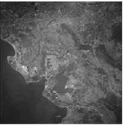
Satellite image of resolution 200×200 pixels shown in Figure 3 is given as input to the shearlet based denoising algorithm for evaluating the performance. The experiment is implemented in MATLAB and shearlet transform can be implemented using ShearLab Software Package.
Let the image is represented by „f ‟ and „w‟ be the zero mean additive white gaussian noise with variance σ2. Then the noisy image can be represented as
fn = f + w (10) The noisy image fn is denoised by thresholding the shearlet coefficients within each subband. The performance of the system is evaluated and compared with other algorithms in terms of peak signal to noise ratio (PSNR) in decibels, which is given by,
PSNR = 20 log10 (255/MSE) (11)
where MSE is the mean square error. Given an image fr(i,j) and original image fo(i,j), then MSE is given by,
MSE = Ʃ [fo(i,j) - fr(i,j)]2 / M×N (12)
where M × N is the size of the satellite image.
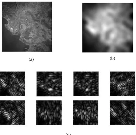
In our experiment, we used a four level shearlet decomposition wherein each level consisting of 3, 3, 4 and 4 numbers of shearing directions respectively. Thus, the number of directional subbands within each level was obtained as 8,8,16 and 16 respectively as the number of directional sub-bands within each level Ns= 2s where Ns is the number of shearing directions. The Figure 4 shows an illustration of first level approximation and detail coefficients of shearlet transform.
We tested the denoising schemes for the image having different standard deviation σ =10 to 25. The performance of proposed method compared to conventional methods is shown in TABLE I. It shows that image denoising using proposed method has high PSNR compared to other state-of-art techniques.
(a) (b)
(c)
To compare the image in terms of visual quality, the Figure 5 shows the denoised images for various denoising methods listed in Table I for satellite image with a standard deviation of σ =10. From Figure 5, it is clear that the proposed method yields a better denoising result.
Techniques /σ σ=10 σ=15 σ=20 σ=25
Bayes Estimate 27.4427 27.0973 26.6439 24.1391
Wavelet Hard Threshold 28.1356 24.7206 22.1067 20.1628
Wavelet Soft Threshold 28.1890 24.7601 22.1375 20.1882
Curvelet Transform 29.6714 28.1962 28.2044 29.3830
Shearlet Transform 30.8480 29.9249 28.0724 25.1209
The Proposed Method 31.9432 30.7294 29.0424 29.0002
(a) (b) (d)
(e) (f)
(a) )
(h) (g)
(a) ) TABLE I
Comparison of the performances of the proposed method to other methods in terms of PSNR (dB)
(c)
V. CONCLUSION
A new approach to denoise satellite image is proposed in this paper via Otsu thresholding optimized using ABC algorithm in shearlet transform domain. Shearlet has high directional sensitivity and are optimally sparse in representing image containing edges. This paper shows a comparison of proposed method with other conventional techniques. The experimental results show that the proposed method outperforms existing methods in terms of PSNR and visual quality and can be selected as an optimal threshold for image denoising.
REFERENCES
1. S.Mallat, and W.L.Hwang, “Singularity Detection and Processing with Wavelets,”IEEE Trans. Information Theory, vol.38, no.2, March 1992, pp.617-643.
2. J.L.Starck, E.J.Candes, and D.L.Donoho, “The curvelet transform for image denoising,”IEEE Trans. on image processing, vol.11, 2002, pp.670-684.
3. M. Do and M. Vetterli, “The contourlet transform: An efficient directional multiresolution image representation,” IEEE Trans. on image processing, vol.14, no. 12, Dec. 2005, pp.2091-2106.
4. G. R. Easley, D. Labate, and W.Q. Lim,“Sparse directional image representations using the discrete shearlet transform,”Appl. Comput. Harmon. Analysis, vol.25, Jan. 2008, pp.25-46.
5. P.J. Burt, and E.H. Adelson, “The Laplacian pyramid as a compact image code,”IEEE Trans. Commun, vol.31, no.4, 1983, pp.532-540.
6. N.Otsu, “A Threshold Selection Method from Gray-Level Histograms” IEEE Transactions On Systems, Man, And Cybernetics, vol.9, no.1,1979,pp.62-66.
7. “Artificial bee colony algorithm” [online] Available:
![Figure 1. The shearlet decomposition of an image [4]](https://thumb-us.123doks.com/thumbv2/123dok_us/1406380.1652991/2.612.182.417.420.546/figure-shearlet-decomposition-image.webp)