A Control Implementation of Quadrotor UAVs Based
on Systems Engineering Concepts
Ngo Van Hien*, Pham Gia Diem
School of Transportation Engineering, Hanoi University of Science and Technology (HUST), Hanoi, Vietnam Emails: [email protected], [email protected], * Corresponding author
Abstract— This paper presents a model-driven control
implementation, which is derived from the Model-Based Systems Engineering (MBSE) approach combined with the Unified Modeling Language (UML)/Systems Modeling Language (SysML), the specification of the Unscented Kalman Filter (UKF) algorithm and hybrid automata in order to conveniently realize and deploy controllers for quadrotor Unmanned Aerial Vehicles (UAVs). The study is step-by-step carried out by the adaptation of quadrotor UAV dynamics and control structure, which are then combined with the specialization of MBSE features as follows: the object-oriented analysis model is defined by the specification of use-case model combined with hybrid automata to closely gather the requirement analysis for control; the object-oriented design model is then built on the defined analysis with the real-time UML/SysML’s features enclosed with the timing concurrency of evolution, in order to intensively design structures and behaviors for the controller; the detailed object-oriented design model is next converted into the object-object-oriented implementation models by using open-source platforms to quickly simulate and deploy the quadrotor UAV controller. Following this proposed model, a trajectory-tracking controller, which permits a quadrotor UAV to reach and follow a reference trajectory, was completely deployed and successfully taken on trial flights.
Index Term— Quadrotor UAV, Model-Based Mechatronic Systems Design; MBSE; Systems Engineering; Unscented Kalman Filter (UKF); Hybrid Automata; Real-Time UML/SysML.
Nomenclature
CLF Control Lyapunov Functions
DoF Degrees of Freedom
GPS Global Positioning System
HA Hybrid Automata
HDS Hybrid Dynamic Systems
IB Integral Backstepping
IDE Implementation Development Environment IGCB Instantaneous Global Continuous Behavior
IMU Inertial Measurement Unit
LOS Line-Of-Sight
MBSE Model-Based Systems Engineering
OMG Object Management Group
OO Object-Oriented
PID Proportional-Integral-Derivative
SMC Sliding-Mode Control
SysML Systems Modeling Language
UAV Unmanned Aerial Vehicles
UKF Unscented Kalman Filter
UML Unified Modeling Language
VTOL Vertical Take Off and Landing
WP Way-Point
I. INTRODUCTION
Over the last decade, Unmanned Aerial Vehicles (UAVs) have seen unprecedented levels of growth, especially the quadrotor UAV. Even though UAVs have been mainly used for military applications, there is a considerable and increasing interest for civilian applications. It is postulated that UAVs will be used extensively in the future for environmental monitoring, traffic monitoring, mapping, surveillance, etc. The quadrotor UAV is one of the miniature UAV types of which operating modes are capable of Vertical Take Off and Landing (VTOL), hovering and horizontal flight; so they can be more easily handled in turbulences such as wind and are easier to design and realize by using a compact airframe [1-3].
In present design and construction of quadrotor UAV controllers, there were many applications that have used the basic control methods combined with soft computing approaches [4-9] to make them more effective for controllers of quadrotor UAVs. For example, a robust controller has been proposed by Liu, Li, Zuo, et al. [10] to address the attitude control problem for uncertain quadrotors with input delays; their designed controller included a nominal controller to achieve desired tracking for the nominal system and a robust compensator to achieve the robust stability of the uncertain system with input delays. The discrete-time Sliding Mode Control (SMC) scheme was applied to design the discrete-time flight controllers for the position and attitude tracking control of a quadrotor UAV that has been presented in [11]; under the discrete-time controllers, the six Degrees of Freedom (DoF) respectively converge to their desired values, the position and velocity tracking errors of all states converge to zero, i.e. the sliding manifolds converge to their sliding surfaces; the obtained simulation results were then promised for the real model of the quadrotor UAV and other complex environments. A hierarchical control strategy based on adaptive radical basis function neural networks and double-loop Integral SMC (IntSMC) has been developed by Li, Wang, Tan, et al. [12] for tracing the position and attitude of quadrotor UAVs that were subjected to sustained disturbances and parameter uncertainties; capabilities of online adaptive estimating of the unknown uncertainties and null tracking error were proved then by using the Lyapunov stability theory. In particular, the different controllers based on Lyapunov
However, the above guidance and control models are based on structural approaches, which focus on the database-driven architecture. Thus, the designed control elements could be difficult to customize and reuse for realizing controllers of different UAV types of which operating modes are capable of VTOL, and for deploying appropriately into various software and hardware platforms. To achieve this goal, the Model-Based Systems Engineering (MBSE) approach [14] is intended to facilitate systems engineering activities that have traditionally been performed using the document-based approach and result in the enhanced specification and design quality, reuse of system specification and design artefacts, and communications among the development team. The output of the systems engineering activities is a coherent model of the system (i.e., system model), where the emphasis is placed on evolving and refining the model using model-based methods and tools [15]. According to the Object Management Group (OMG) [16], the Unified Modeling Language (UML) appeared to us to be essential for its visual object-oriented design support, which has been largely spread and appreciated in the software industry [17, 18]. Furthermore, the System Modeling Language (SysML) [19], which is a UML profile for systems engineering, has been standardized by OMG. SysML supports the specification, analysis, design, verification and validation of a broad range of complex systems. But both UML and SysML lack the constructs for modeling time and duration constraints of industrial control systems [20-22]. Thus, the MBSE approach can be specialized by using the real-time UML version [23-26] together with SysML (i.e. the real-time UML/SysML), in order to conveniently perform the whole of development lifecycle for real-time and embedded control systems, e.g. the quadrotor UAV controller.
From the above considered points, this paper is focused on the implementation of a control model integrated the quadrotor UAV dynamics using MBSE approach combined with the real-time object paradigms, Unscented Kalman Filter (UKF) algorithm and specialization of HA features, which can permit us to intensively realize and deploy the quadrotor UAV controller, and also allow the designed and implemented
control components to be customizable and re-usable in the realization of new applications for various UAV types of which operating modes are capable of VTOL. In our current model, the quadrotor UAV dynamics and control structure are adapted for the quadrotor UAV controller that are then combined with the detailed models as follows: The Object-Oriented (OO) analysis, design and implementation models; this control system permits a quadrotor UAV to track a desired reference trajectory in the Cartesian space. Here, the OO analysis model includes the use-case model specialized closely with an implemented function block diagram, the UKF algorithm and hybrid automata (HA) to precisely capture the requirement analysis for a quadrotor UAV controller; the OO design model is built on the identified OO analysis model by specifying the real-time UML/SysML formalisms to entirely design the real-time control capsules together with their ports and protocols in detail. The detailed OO design elements are then converted into the OO implementation models by using open-source platforms such as OpenModelica [27] and
Arduino [28] in order to quickly simulate, realize and deploy the quadrotor UAV controller. Finally, a planar trajectory-tracking controller of an application of quadrotor UAV was completely deployed and tested.
The paper is structured as follows: The quadrotor UAV dynamic model and control structure are introduced in Section II. Section III presents the details of MBSE-driven development to intensively realize quadrotor UAV controllers, including the OO analysis, design and implementation components. Following this described model, in Section IV, it is applied to a case study. Conclusions and future works are reported in Section V.
II. QUADROTOR UAVDYNAMICS AND CONTROL
STRUCTURE
A. Modeling quadrotor UAV dynamics for control
From the large field of guidance, navigation and control of aerial vehicles in [6, 29-32], the six DoF dynamic model of a quadrotor UAV in body coordinate frame can be written in equation systems (1).
{
mẍ = (sinψsinϕ + cosψsinθcosϕ) ∑4i=1Ti− ∑4i=1Hxi− 1
2CxAcρẋ|ẋ|
mÿ = (−cosψcosϕ + sinψsinθcosϕ) ∑4i=1Ti− ∑4i=1Hyi− 1
2CyAcρẏ|ẏ|
mz̈ = mg − (cosψcosϕ) ∑4i=1Ti
Ixxϕ̈ = θ̇ψ̇(Iyy− Izz) + Jrθ̇Ωr+ l(−T2+ T4) − h(∑4i=1Hyi) + (−1)i+1∑4i=1Rmxi
Iyyθ̈ = ϕ̇ψ̇(Izz− Ixx) − Jrϕ̇Ωr+ l(T1− T3) − h(∑4i=1Hxi) + (−1)i+1∑4i=1Rmyi
Izzψ̈ = θ̇ϕ̇(Ixx− Iyy) + JrΩ̇r+ (−1)i∑4i=1Qi+ l(Hx2− Hx4) + l(Hy3− Hy1)
(1)
Where: Ixx,Iyy and Izz are inertia moments; , , are respectively Roll, Pitch, Yaw angles; Jr presents the rotor inertia; H is a set of hub forces; Rm is a set of rolling moments; Ti presents the thrust force (i = 1,4̅̅̅̅); r is the overall residual propeller angular speed; Ac is fuselage area; C is the propulsion group cost factor; is the air density; Qi presents the drag moment; h and l are respectively vertical distance and horizontal distance: propeller center to center of gravity; x, y and z define the position in body coordinate frame.
To develop controllers of quadrotor UAVs, it is advisable
to simplify the model in order to comply with the real-time constraints of the embedded control loop. In our case study, we proposed that hub forces and rolling moments are neglected and thrust and drag coefficients are supposed constant. The system can be rewritten in state-space form 𝐱̇ = 𝐟(𝐱, 𝐮) with u inputs vector and x state vector.
respectively the thrust and drag factors.
{
u1= b(ω12+ ω22+ ω32+ ω42)
u2= b(−ω22+ ω42)
u3= b(−ω12+ ω32)
u4= d(−ω12+ ω22− ω32+ ω42)
(3)
𝐱 is a 12-dimensional state vector for describing the motion of quadrotor UAV that is written as follows:
𝐱 = [x, y, z,, θ, ψ, x,̇ y,̇ z,̇ ϕ̇, θ̇, ψ̇]T (4) A discrete state-space representation is required for modeling the quadrotor UAV controller in order to use a recursive estimation filter of motion states, e.g. the UKF; the developed system can be then described by a set of equations (5).
{𝐱𝐤= 𝐟𝐤−𝟏(𝐱𝐤−𝟏, 𝐮𝐤−𝟏) + 𝐰𝐤−𝟏
𝐲𝐤= 𝐡𝐤(𝐱𝐤) + 𝐯𝐤
(5)
Where: xk is the vector of state variables at the kth instant of x; uk and yk are respectively the inputs and outputs of the system; hk, wk and vk are respectively the measurement function, additive process and measurement noise; the first equation in (5) is called the system’s evolution equation, while the second one is called the measurement equation.
B. Using control structure and technique
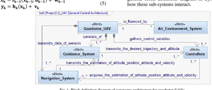
Within the autonomy architecture of quadrotor UAVs are three main sub-systems. These are the guidance system, which is responsible for generating the trajectory for the vehicle to follow; the navigation system, which produces an estimation of the current state of the vehicle; and the control system, which calculates and applies the appropriate forces to maneuver the vehicle. This allows the quadrotor UAV to track a desired trajectory even in the presence of unknown weather disturbances issued from the environment. Fig. 1 shows out a general block definition diagram in SysML, which captures how these sub-systems interact.
Fig. 1. Block definition diagram of autonomy architecture for quadrotor UAVs.
In addition, the problem of designing autonomous flight controllers for quadrotor UAVs is equally challenging because these controllers are closely connected with the dynamic models. Therefore, these control systems must take account of models with discrete events and continuous behaviors that can be called Hybrid Dynamic Systems (HDS) described in [33-35]. Besides, controlled systems do not always have the same behavior because they are associated with validity hypotheses to check at any moment; the security requirement forces to envisage events, and behaviors different from nominal behaviors. Hence, the behaviors of such systems are complex, and can be modeled by HA [22, 36-38]. From the above described quadrotor UAV dynamic model and general control structure together with characteristics of HDS, controllers of quadrotor UAVs can be considered as HDS. These control systems have the continuous/discrete parts and their interactions such as the motional components, e.g. horizontal transferring, VTOL, rotation, roll, pitch and yaw, and external interacting events from the guidance and navigation system, and environmental disturbances. In our model, we are interested in developing the trajectory-tracking controller of quadrotor UAVs, so we can use this hybrid dynamic model to find out the control algorithms with a specific guidance law such as the Line-Of-Sight (LOS) guidance implemented in [39-41].
Furthermore, Bouabdallah [13] has made the theoretical simulation and experiment evaluations for a quadrotor UAV controller with several control techniques using different approaches such as: Lyapunov theory, PID control, optimal control theory, Backstepping and SMC; it clearly brought out that the way is to follow a combination between PID and Backstepping into the so-called Integral Backstepping (IB) [42]. The goal of this approach was to bring together the robustness against disturbances offered by Backstepping and robustness against model uncertainties offered by the integral action. The stability analysis is performed by using Lyapunov
theory; it means that IB is a recursive design technique using Control Lyapunov Functions (CLF). The CLF concept is a generalization of Lyapunov design results by, for instance, [43-45]. Hence, this can permit us to design the control law of quadrotor UAV controllers combined with the IB technique, the specialization of HA features and CLF for more complex flight maneuvers than a simple hovering.
III. MBSE-DRIVEN DEVELOPMENT FOR A QUADROTOR
UAVCONTROLLER
A. Object-oriented analisys model for a quadrotor UAV controller
guidance [39], we have developed the main use case model of controllers as shown in Fig. 2 combined with an example of trajectory-tracking scenarios and local state machine of the “Track a desired trajectory” use case which are respectively
shown in Fig. 3a and Fig. 3b.
Fig. 2. Main use case model for a quadrotor UAV controller.
Fig. 3. An example of trajectory-tracking scenarios (a) and the local state machine of the “Track a desired trajectory” use case (b) for a quadrotor UAV
controller.
Here, MDS is the Measurement Display System consisting of the guidance and navigation systems, because both of them essentially act as a signal supplier for the controllers of
quadrotor UAV; AES is the Air Environment System including disturbances generated by the weather. In the use-case model, it is necessary to provide industrial control constraints, e.g. the maximum tilted angle, velocity, altitude and other safe flying modes of the developed quadrotor UAV in order to ensure the operational safety of this system. In Fig. 3a, the “loop(5)”
fragment is typical value in practice of LOS guidance, which can be found in [41].
Actually, the real-time UML/SysML version lacks the constructs for modeling internal continuous behaviors for each state on the state machine diagram, an implemented functional block diagram must be then defined in order to model continuous behaviors of the quadrotor UAV controller with events issued from outside. Starting from the considered dynamic model of quadrotor UAV, the general architecture and the identified use case model with LOS guidance, we propose an implemented functional diagram for the quadrotor UAV controller as shown in Fig. 4.
Fig. 4. An implemented functional block diagram for the quadrotor UAV controller.
Where: Desired trajectory and Take-off/Landing actions respectively give the desired position (xd, yd) altitude (zd) to the position and altitude controller; Td is the desired overall thrust; the position controller receives the quadrotor UAV’s position (x, y) and desired thrust, it outputs desired roll (d) and pitch (d) while desired yaw (d) comes directly from the guidance system; the attitude controller gives then the desired motor speeds (d1, d2, d3, d4) to the motor controllers; ,, and T are respectively the overall torque and thrust acting on the quadrotor UAV. In our current model, the IB technique combined with the UKF algorithm are used for altitude, position, attitude and velocity control. The IB expansions combined with CLF for quadrotor UAV controllers were well known by many quadrotor UAV control applications, for instance, [13, 43, 46-48]. The state-space models (2), (4) and (5) are used for the estimation and prediction of the altitude, position, attitude and velocity corresponding to the sensors installed on the quadrotor UAV that are implemented in the Navigation System block. The navigation filter is based on UKF that composes of the
of process and measurement noise, assumed as zero mean stationary white noises with zero cross-correlation; the state is recursively estimated starting from the assumed initial conditions as follows: 𝐱̂0|0= 𝐱0 and 𝑃0|0= 𝟎12×12; the Unscented Transform (UT) is a deterministic sampling
technique, which allows us to compute the mean and the covariance matrix of a random variable; it undergoes a generic nonlinear transformation by propagating a minimum set of its samples and exploiting the knowledge of the mean and of the covariance of the starting variable.
Algorithm 1.
Navigation filter based on UKF for a quadrotor UAV controller. Function UKF algorithm
Step UKF predict
Data : 𝐱̂𝑘−1|𝑘−1, 𝑃𝑘−1|𝑘−1, 𝐟𝑘−1(. ) Result : 𝐱̂𝑘|𝑘−1, 𝑃𝑘|𝑘−1
(𝐱̂𝑘|𝑘−1, 𝑃̅𝑘|𝑘−1) = 𝑈𝑇 (𝐱̂𝑘−1|𝑘−1, 𝑃̅𝑘−1|𝑘−1, 𝐟𝑘−1(. )) ; 𝑃𝑘|𝑘−1= 𝑃̅𝑘|𝑘−1+ 𝑄𝑘−1;
end
Step UKF update Data : 𝐱̂𝑘|𝑘−1, 𝑃𝑘|𝑘−1, 𝐡𝑘(. ) Result : 𝐱̂𝑘|𝑘, 𝑃𝑘|𝑘 (𝐲̂𝑘|𝑘−1, 𝑆̅𝑘, 𝑃𝑘
𝑥𝑦
) = 𝑈𝑇 (𝐱̂𝑘|𝑘−1, 𝑃𝑘|𝑘−1, 𝐡𝑘−1(. )) ; 𝑆𝑘= 𝑅𝑘+ 𝑆̅𝑘;
𝐿𝑘= 𝑃𝑘 𝑥𝑦
𝑆𝑘−1; 𝐞𝑘= 𝐲𝑘− 𝐲̂𝑘|𝑘−1; 𝐱̂𝑘|𝑘= 𝐱̂𝑘|𝑘−1+ 𝐿𝑘𝐞𝑘; 𝑃𝑘|𝑘= 𝑃𝑘|𝑘−1− 𝐿𝑘𝑆𝑘𝐿𝑇𝑘; end
In the OO analysis model, HA are specialized to describe mathematical behaviors, i.e. the dynamic model of quadrotor UAV including terms as Situations, Continuous State Variables, Event, Transition, Global Continuous Behavior and
Invariants. A HA of the quadrotor UAV controller is defined in equation (6).
HQuadrotor UAV = (Q, X, , A, Inv, F, qo, xco) (6) Where:
Q is a set of states describing flying modes of
HQuadrotor UAV, e.g. the motion in horizontal translations, hovering, VTOL, rotations, roll, pitch, and yaw, which are combined with the local state machine oriented towards control modes (Fig. 3b) in permutations. Q can be called situations of the quadrotor UAV controller; qo is the initial situation.
X presents the continuous state space of HQuadrotor UAV, Xn, x
co is the initial value of this space, e.g. continuous components of the quadrotor UAV controller; xcX presents variables of which values are average in the occurred noises.
is a finite set of events, e.g. external interacting events from the guidance and navigation system, and environmental disturbances.
A is a set of transitions defined by (q, Guard, , Jump, q’) and represented by an arc between situations, here:
qQ, q’Q; Guard is a subset of the state space in which the continuous state must be, so that the transition can be crossed;
Jump represents the continuous state transformation during the change of situation; presents the event being associated in the transition.
Inv is an application, which associates a subset of the state space in each situation; it is called the invariant of the situation, in which the continuous state must remain, when the situation is q, the continuous state must verify xcInv(q).
F is defined by using the six DoF dynamic model of quadrotor UAV, and the implemented functional block diagram (Fig. 4); the evolution of continuous state is occurred when the situation is activated.
The constraints as follows: is considered in term of inputs/outputs and internality/externality; X contains input/output signals were applied to globally perform the HA
evolution of a quadrotor UAV controller. In addition, the realization hypotheses of the HA evolution, which permit the invariant Inv and guard control Guard combined with transitions can generate internal events for the quadrotor UAV controller, can be found in the author’s thesis [49].
B. Object-oriented design model for a quadrotor UAV controller
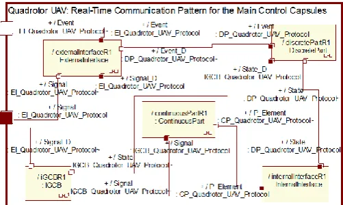
Following the above specified analysis model, the 5 main control capsules are then defined that take part in the HA realization of the quadrotor UAV being developed: the continuous part’s capsule, discrete part’s capsule, internal interface’s capsule, external interface’s capsule and Instantaneous Global Continuous Behavior (IGCB’s capsule). Fig. 5 indicates the real-time communication pattern of main control capsules.
Fig. 5. Real-time communication pattern for the main control capsules for a quadrotor UAV controller.
The discrete part’s capsule contains a set of situations Q and transitions A in HA of the quadrotor UAV controller (i.e. the macro-motion in horizontal translations,
hovering, VTOL, and rotations: roll, pitch, and yaw, which are combined with the local state machine (Fig. 3b) in permutations.
[50] with two sub-capsules called RendezVous and Semaphore.
The IGCB’s capsule contains concrete global continuous behaviors of the quadrotor UAV being developed at time given just as f F in its HA. f is derived from (1), (2), (4) and (5) and the implemented functional block diagram (Fig. 4). This is also taken part into Algorithm 1 to estimate the position, depth, attitude and velocity of the quadrotor UAV. Each global continuous behavior corresponds to a situation in this HA.
The internal interface’s capsule verifies the Inv in HA of the quadrotor UAV controller, and generates internal events; so that the discrete part’s capsule can make its own evolution by these events.
The external interface’s capsule is an intermediary, which receives or sends episodic events and periodic signals between the developed quadrotor UAV and their interacted systems such as AES and MDS in our model.
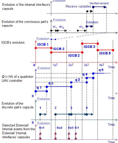
Fig. 6 describes in detail the timing concurrency of evolutions for the above real-time communication pattern of main control capsules. Here, Ee1, Ee2, Ee3… are the external events coming from the external interface’s capsule; Ei1, Ei2, Ei3… are internal events issued by the evolution of the internal interface’s capsule; q1, q2, q3… indicate the concrete situations in HA of the quadrotor UAV controller being developed; ec1, ec2, ec3… represent the evolutions of continuous elements in the continuous part’s capsule; and T is a sampling period of the IGCB’s capsule. The realization hypotheses of timing concurrency for capsule evolutions in Fig. 6 are applied as follows:
If the end of the discrete part’s evolution is located before or just at the sampling date of the IGCB’s capsule, then the current IGCB model will change to the new IGCB model corresponding to this evolution;
If the end of the discrete part’s evolution is located after of appearing sampling date (T), then the current IGCB model is not commutated;
If an event appears during the evolution of the local state machine of UAV application (e.g. Fig. 3b), then this event is immediately memorized and solved later on;
All of the external and internal events have the same process by the discrete part’s capsule;
During the sampling period of the IGCB’s capsule, the continue part’s capsule, internal interface’s capsule and discrete part’s capsule make their own evolutions to possibly commutate to a new IGCB model, the IGCB continuous model remains in its current mode for this period;
So during the period of the IGCB’s capsule, the current IGCB model can detect two or more appeared situations (i.e. Q in HA), then the IGCB’s capsule synchronizes all these situations just at the end of this period with the null timing duration; the current IGCB model subsequently changes to a new IGCB model, which corresponds to the last appeared situation during this period.
In addition, the reusability is very important to implement controllers for different applications of UAVs of VTOL type because it permits the development time and cost to be reduced. The various reusable views in the development phase are considered as follows: The reusable view is based on the virtual mechanism of objects, classes or class hierarchies; the
other re-use view can be based on design components, e.g. the implemented functional block diagram, the local state machine of quadrotor UAV controller and generic state machine of main control capsules that can be specified to develop various control applications of quadrotor UAVs using the same technique. More details of design components and reusability rules can be seen in the author’s thesis [49].
Fig. 6. Timing concurrency of evolutions for main control capsules of a quadrotor UAV controller.
C. Object-oriented implementation models for a quadrotor UAV controllers
To carry out the quadrotor UAV controller, the design model is firstly implemented to the Object-Oriented (OO) simulation model, that is transformed from the above built design by using tools such as IBM Rational Rose RealTime or
IBM Rational Software Architect RealTime [51] and
Modelica/OpenModelica [27, 52]. The OpenModelica
environment allows most of the expression, algorithm, and function parts of Modelica to be executed interactively, as well as equation models and Modelica functions to be compiled into efficient C/C++ codes. The generated C/C++ codes are combined with a library of utility functions, a run-time library and a numerical Differential Algebraic Equation (DAE) solver. The obtained simulation results in
which are based on the object-oriented Implementation Development Environment (IDE), e.g. the Arduino’s IDE [28]
in order to completely realize the quadrotor UAV controller with compatible microcontrollers, e.g. ATMEGA32-U2 and
STM32 Cortex-M4 microcontrollers [28]. A sketch of the above described model transformations is shown as Fig. 7. Here, the transformations are performed through the round-trip engineering (i.e. the forward and reverse engineering) of the intermediate C++ codes, which are issued from the models depicted in IBM Rational Rose RealTime or IBM Rational Software Architect RealTime, OpenModelica tools and the
Arduino’s IDE.
Fig. 7. Sketch of Design-Implementation model transformation for quadrotor UAV controllers.
Fig. 8. State pattern of HA for a quadrotor UAV controller.
In addition, the HA of a quadrotor UAV controller can be automatically implemented in the object-oriented convention by using the State Pattern described in [50, 53]. This pattern allows an object to alter its behavior when its internal state changes; the object will appear to change its class. Following this pattern, an implementation structure of HA (Fig. 8) is specified to improve the evolution of the quadrotor UAV controller. In the case, the Arduino’s platforms are used to
realize the quadrotor UAV controller, an example of the main generated C++ codes of the HA’s state pattern, which is verified and compiled to fit in ATMEGA32-U2 and STM32 Cortex-M4 microcontrollers by using Arduino IDE version 1.8.0 [28], is shown in the appendix.
IV. APPLICATION
Following the above proposed model, a new trajectory-tracking controller was developed that permits a quadrotor UAV to reach and follow a geometric reference path in the
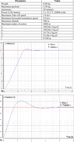
Cartesian space starting from a given initial configuration. The main characteristics of this quadrotor UAV are summarized in Table I.
Table I
Main characteristics of the Developed Quadrotor UAV.
Parameter Value
Weight 8.00 kg
Maximum payload 4.50 kg
Autonomy 20 minutes
Power Li-Po battery 2 x 22.2 V, 20000 mAh Maximum Take-off speed 3.0 m/s
Maximum horizontal translation speed 5.0 m/s Maximum altitude 500 m Maximum radius of action 4900 m
Ixx 100.84e-3 kg.m2
Iyy 100.84e-3 kg.m2
Izz 24.72e-2 kg.m2
Jr 54.36e-5 kg.m2
l 0.550 m
Fig. 9. Transient control responses in z-direction (a) and in x-direction (b).
transient control response in x-direction, when the quadrotor UAV received a drive event of Transferring with a desired distance of 10m in x-direction (x-Position) from the current position. All of the obtained simulation results permit us to theoretically evaluate the control performance of this system within the control criteria such as the admissible timing response, transition and static errors. From that point, we can decide to choose the designed control elements and their parametric values to perform the realization phase of this application.
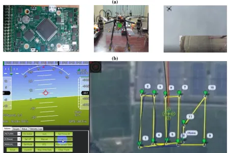
The test bench of trial flights was installed on the Arduino
platform that combined with Inertial Measurement Unit (IMU)
MPU6000 with working frequency 100Hz [54], Global Positioning System (GPS) Ublox Neo 6M with working frequency 10Hz [55], ATMEGA32-U2 and STM32 Cortex-M4
microcontrollers [28] (Fig. 10a), and can be programmed by using the object-oriented embedded programming C++. The test scenarios were mainly based on the local state machine (Fig. 3b); we illustrate here one of main test cases as follows: the quadrotor UAV autonomously reaches and follows a desired zigzag-lined trajectory enclosed with various heading angles, the maximum trajectory error is about 0.8 m (Fig. 10b).
(a)
(b)
Fig. 10. Setting up and testing the controller for the developed quadrotor UAV (a); Quadrotor UAV reaches and follows a desired zigzac-lined trajectory (b).
Based on the comparison between the experimental data of these trial tests and the obtained experimental results of the existing results in the author’s report [1], in which the PID regulator was only implemented for the controlling the altitude, position, attitude and velocity of the same physical quadrotor UAV model, the trajectory-tracking controller of this quadrotor UAV was improved on the stabilized control duration and trajectory error, which were diminished respectively about 1.2 s and 0.4 m. In the current application, the standard control method of IB and the UKF algorithm were used for the altitude, position, attitude and velocity control and the PID regulators were applied to the block of motor controllers, which permit us to implement the functional block diagram (Fig. 4) for building up the ICCB’s capsule of the OO design model. Within limit of the paper, we do not present here all the artefacts of the analysis, design and realization models, and test results of this developed quadrotor UAV controller, so detailed results can be seen in the author’s thesis [49].
V. CONCLUSIONS AND FUTURE WORK
This paper presented a systems engineering-based implementation to intensively realize controllers for quadrotor UAVs whose global behaviors can be considered as the HDS. This model is mainly based on the specializations of MBSE features combined with the real-time UML/SysML, HA and UKF algorithm to conveniently analyze, design, realize and deploy the control parts of system. The quadrotor UAV dynamics and control structure are adapted for the control that are combined with the specialization of MBSE features including the object-oriented analysis, design and implementation components. Based on this proposed model, a trajectory-tracking controller of a low-cost quadrotor was completely deployed and tested out Arduino ATMEGA U2 and STM32-Cortex-M4
microcontrollers.
Advantages:
+ It highlights a global model of top level, which can combine the use-case model with the discrete models and continuous models (i.e. hybrid automata with the UKF algorithm) to estimate the quadrotor UAV states.
+ The OO design-implementation separation and its model transformation allow the design model to distinguish which elements are customized and reused in new UAV applications of which operating modes are capable of VTOL, hovering and horizontal flight.
+ The user benefits from a chain of commercial or open-source software such as IBM Rational Rose RealTime or
IBM Rational Software Architect RealTime, OpenModelica
and Arduino library. It could take advantage of the efforts of communities and just has to specialize some programming codes.
+ Arduino microcontrollers are used by a large part of the community of embedded system development in which designers use open-source solutions.
+ Arduino platform can sense the environment by receiving input from a variety of sensors to allow for the extension of complex systems.
Disadvantages:
+ The product is naturally less specialized and could possibly loose the speed performance. It may require optimization.
+ Development engineers may be needed to train for gathering up skills in different IDEs that permits them to manage the interfaces between tools.
+ There is still no version of real-time OpenModelica
and so it could be difficult to quickly perform the hardware-in-the-loop simulation.
+ It could take time to compile and upload the implemented programs in Arduino IDE.
In the near future, we will investigate in our application strategy to extend it more effective in order to completely make up controllers for balancing search and target response in cooperative team of various UAV types.
ACKNOWLEDGMENT
This work was supported by the KC05.21/16-20 project funded by State, from the Ministry of Science and Technology of Vietnam.
REFERENCES
[1] Hung, N.P., Diem, P.G., Hien, N.V., et al., Research on, design and manufacture a micro-unmanned aerial flying autonomously at desired trajectories, Final report of research project, code: KC03.TN03/11-15, Hanoi University of Science and Technology., Hanoi, Vietnam, 2013. [2] Phang, S.K., Li, K., Chen, B.M., et al., Systematic Design Methodology
and Construction of Micro Aerial Quadrotor Vehicles, in: K. P. Valavanis, G.J. Vachtsevanos (Eds.) Handbook of Unmanned Aerial Vehicles, Springer, Dordrecht, Heidelberg, New York, London, 2015, pp. 181-206.
[3] Dalamagkidis, K., Classification of UAVs, in: K. P. Valavanis, G.J. Vachtsevanos (Eds.) Handbook of Unmanned Aerial Vehicles, Springer, Dordrecht, Heidelberg, New York, London, 2015, pp. 83-91.
[4] Lazim, I.M., Husain, A.R., Basri, M.A.M., et al., Feedback Linearization with Intelligent Disturbance Observer for Autonomous Quadrotor with Time-varying Disturbance, International Journal of Mechanical &
Mechatronics Engineering, IJMME-IJENS, ISSN 2227-2771, 18, pp. 47-55, 2018.
[5] Saeedi, M.A., Mirzaee, M., A New Backstepping Sliding Mode Control System to prevent Roll Instability of a Four-Wheeled Vehicle, International Journal of Mechanical & Mechatronics Engineering, IJMME-IJENS, ISSN 2227-2771, 19, pp. 178-186, 2019.
[6] Motea, Z.M., León, R.E.A., Abidin, M.S.Z., Empirical Modeling and Control of Quadrotor Unmanned Aerial Vehicle, International Journal of Mechanical & Mechatronics Engineering, IJMME-IJENS, ISSN 2227-2771, 18, pp. 63-74, 2018.
[7] Raheem, F.A., Sadiq, A.T., Abbas, N.A.F., Robot Arm Free Cartesian Space Analysis for Heuristic Path Planning Enhancement, International Journal of Mechanical & Mechatronics Engineering, IJMME-IJENS, ISSN 2227-2771, 19, pp. 29-42, 2019.
[8] Abdelaal, M., Bahgat, A., Emara, H.M., et al., Real-Time External Control Coupled with Vision-Based Control for an Industrial Robotic Arm to Pick and Place Moving Object on a Conveyor Belt, International Journal of Mechanical & Mechatronics Engineering, IJMME-IJENS, ISSN 2227-2771, 19, pp. 123-131, 2019.
[9] Alandoli, E.A., Shah, H.N.M., Sulaiman, M., et al., PD/H-∞ Integrated Controller for Position Tracking and Vibration Suppression of Flexible Link Manipulator System, International Journal of Mechanical & Mechatronics Engineering, IJMME-IJENS, ISSN 2227-2771, 18, pp. 54-61, 2018.
[10] Liu, H., Li, D., Zuo, Z., et al., Robust attitude control for quadrotors with input time delays, Control Engineering Practice, Elsevier, ISSN 0967-0661, 58, pp. 142-149, 2017.
[11] Xiong, J.J., Zhang, G., Discrete-time sliding mode control for a quadrotor UAV, Optik - International Journal for Light and Electron Optics, Elsevier, ISSN 0030-4026, 27, pp. 3718-3722, 2016.
[12] Li, S., Wang, Y., Tan, J., et al., Adaptive RBFNNs/integral sliding mode control for a quadrotor aircraft, Neurocomputing, Elsevier, ISSN 0925-2312, 216, pp. 126–134, 2016.
[13] Bouabdallah, S., "Design and control of quadrotors with application to autonomous flying", PhD Thesis, École Polytechnique Fédérale de Lausanne, Suisse, 2007.
[14] INCOSE, Systems Engineering Vision 2025, INCOSE, San Diego, C.A. 92111-2222, USA, 2014.
[15] INCOSE. Object-Oriented Systems Engineering Method. Available:
https://www.incose.org/incose-member-resources/working-groups/transformational/object-oriented-se-method, 2019 (accessed April 2019).
[16] OMG, Documents Associated With Unified Modeling Language™ (UML® Version 2.5), OMG formal/15-03-01, http://www.omg.org/spec/UML/2.5/, OMG, 2015.
[17] Ciccozzi, F., Malavolta, I., Selic, B., Execution of UML models: a systematic review of research and practice, Software & Systems Modeling, Springer, ISSN 1619-1366, 18, pp. 2313–2360, 2018. [18] Selic, B., Using UML for modeling complex real-time systems, Lecture
Notes in Computer Science, Springer, ISSN 0302-9743, 1474, pp. 250-260, 1998.
[19] OMG, SysML Specifications Version 1.4, OMG formal/2015-06-03, http://www.omg.org/spec/SysML/1.4/, OMG, 2015.
[20] Baouya, A., Bennouar, D., Mohamed, O.A., et al., A quantitative verification framework of SysML activity diagrams under time constraints, Expert Systems with Applications, Elsevier, ISSN 0957-4174, 42, pp. 7493-7510, 2015.
[21] Hien, N.V., Diem, P.G., A Model-Based Control Design of Industrial Hybrid Dynamic Systems in the scope of KC05.21/16-20 project. Part I: Theoretical Foundations, International Journal of Mechanical & Mechatronics Engineering, IJMME-IJENS, ISSN 2227-2771, 19, pp. 88-95, 2019.
[22] Soriano, T., Hien, N.V., Tuan, K.M., et al., An object-unified approach to develop controllers for autonomous underwater vehicles, Mechatronics - The Science of Intelligent Machines, Elsevier, ISSN 0957-4158, 35, pp. 54-70, 2016.
[23] OMG, UML Profile for MARTE: Modeling and Analysis of Real-Time Embedded Systems, OMG Formal Version. http://www.omg.org/spec/MARTE/, OMG, 2011.
[25] Selic, B., Gerard, S., Modeling and Analysis of Real-Time and Embedded Systems with UML and MARTE, Elsevier, USA, 2014. [26] Mubeen, S., Nolte, T., Sjödin, M., et al., Supporting timing analysis of
vehicular embedded systems through the refinement of timing constraints, Software & Systems Modeling, Springer, ISSN 1619-1366, 18, pp. 39-69, 2019.
[27] OpenModelica. OpenModelica Software, Version 1.13. Available: https://www.openmodelica.org/, 2019 (accessed January 2019).
[28] Arduino. Open-source electronics prototyping platform for hardware and software. Available: http://www.arduino.cc/, 2019 (accessed April 2019). [29] Nelson, R.C., Flight Stability and Automatic Control (2nd Edition),
McGraw Hill, Singapore, 1998.
[30] Valavanis, K. P., Vachtsevanos, G.J. (Eds.), Handbook of Unmanned Aerial Vehicles, Springer, Dordrecht, Heidelberg, New York, London, 2015.
[31] Carrillo, L.R.G., López, A.E.D., Lozano, R., et al., Quad Rotorcraft Control: Vision-Based Hovering and Navigation, Springer, London, Heidelberg, New York, Dordrecht, 2013.
[32] Zhang, X., Duan, H., An improved constrained differential evolution algorithm for unmanned aerial vehicle global route planning, Applied Soft Computing, Elsevier, ISSN 1568-4946, Volume 26, pp. 270-284, 2015.
[33] Carloni, L.P., Passerone, R., Pinto, A., et al., Languages and Tools for Hybrid Systems Design, now Publishers Inc., Boston, 2006.
[34] Fishwick, P.A. (Ed.), Handbook of Dynamic System Modeling, Taylor & Francis Group, USA, 2007.
[35] Soriano, T., Sghaier, A., Hien, N.V., Mechatronics Design from an Object-Oriented Point of View, WSEAS Transactions on Communications, ISSN 1109-2742, 3, pp. 282-287, 2004.
[36] Henzinger, T. A., Kopke, P. W., Puri, A., et al., What's Decidable about Hybrid Automata?, Journal of Computer and System Sciences, Elsevier, ISSN 0022-0000, 57, pp. 94-124, 1998.
[37] Hien, N.V., "Une Méthode Industrielle de Conception de Commande par Automate Hybride Développée en Objets", Thèse de Doctorat, Univertsité de Marseille III, France, 2001.
[38] Hien, N.V., He, N.V., Diem, P.G., A model-driven implementation to realize controllers for Autonomous Underwater Vehicles, Applied Ocean Research, Elsevier, ISSN 0141-1187, 78, pp. 307-319, 2018.
[39] Lekkas, A.M., Fossen, T.I., Integral LOS Path Following for Curved Paths Based on a Monotone Cubic Hermite Spline Parametrization, IEEE Transactions on Control Systems Technology, ISSN 1063-6536, 22, pp. 2287 - 2301, 2014.
[40] Liu, J.H., Shan, J.Y., Liu, Q., Optimal pulsed guidance law with terminal impact angle constraint, Journal of Aerospace Engineering, Institution of Mechanical Engineers, SAGE Publishing, ISSN 0954-4100, 231, pp. 1993–2005, 2017.
[41] Béla, L., Lorinc, M., Nonlinear Control of Vehicles and Robots, Springer2011.
[42] Krstic, M., Kanellakopoulos, L., Kokotovic, P.V., Nonlinear and Adaptive Control Design, John Wiley & Sons, USA, 1995.
[43] Xiong, J.J., Zheng, E.H., Position and attitude tracking control for a quadrotor UAV, ISA Transactions®, Elsevier, ISSN 0019-0578, 53, pp. 725–731, 2014.
[44] Jayakrishnan, H.J., Position and Attitude control of a Quadrotor UAV using Super Twisting Sliding Mode, IFAC-PapersOnLine, Elsevier, ISSN 2405-8963 49, pp. 284-289, 2016.
[45] Cabecinhas, D., Cunha, R., Silvestre, C., A nonlinear quadrotor trajectory tracking controller with disturbance rejection, Control Engineering Practice, Elsevier, ISSN 0967-0661, 26, pp. 1-10, 2014.
[46] Bouchoucha, M., Seghour, S., Osmani, H., et al., Integral Backstepping for Attitude Tracking of a Quadrotor System, Electronics and Electrical Engineering, ISSN 1392-1215, 116, pp. 75-80, 2011.
[47] Fang, Z., Gao, W., Adaptive integral backstepping control of a Micro-Quadrotor, IEEE International Conference on Intelligent Control and Information Processing (ICICIP), IEEE, Harbin Institute of Technology Harbin, China, pp. 910-915, 2011.
[48] Huo, X., Huo, M., Karimi, H.R., Attitude Stabilization Control of a Quadrotor UAV by Using Backstepping Approach, Mathematical Problems in Engineering, Hindawi, ISSN 1024-123X, 2014, pp. 9 pages, 2014.
[49] Diem, P.G., "An Object-Oriented Design Method for Controllers of Quadrotor Unmanned Aerial Vehicles (UAV)", Ph.D. Thesis, Hanoi University of Science and Technology, Vietnam, 2017.
[50] Douglass, B.P., Design Patterns for Embedded Systems in C - an Embedded Software Engineering Toolkit (1st edition), Elsevier, Oxford, UK, 2011.
[51] IBM. IBM Rational software and Training kit. Available: https://ibm.onthehub.com, 2019 (accessed March 2019).
[52] Fritzson, P., Principles of Object Oriented Modeling and Simulation with Modelica 3.3: A Cyber-Physical Approach, Wiley & Sons, USA, 2015. [53] Gamma, E., Helm, R., Johnson, R., et al., Design Patterns: Elements of
Reusable Object-Oriented Software, Addison-Wesley, Oxford, UK, 1995. [54] InvenSense. Sensor System on Chip. Available:
http://www.invensense.com/, 2019 (accessed February 2019).
[55] u-blox. Gobal leader in wireless communications and positioning semiconductors and modules for the industrial, automotive and consumer markets. Available: https://www.u-blox.com, 2018 (accessed December 2018).
APPENDIX
An example of the “HA_Quadrotor_UAV.h” header and “HA_Quadrotor_UAV.cpp” implementation files of HA library for the developed quadrotor UAV were implemented, verified and compiled to fit in ATMEGA32-U2 and STM32 Cortex-M4 microcontrollers for the developed by using Arduino IDE version 1.8.0.
/*******************************************************
Login : Users
Component : DefaultComponent
Configuration : DefaultConfig
Model Element : HA_Quadrotor_UAV
File Path : \DefaultConfig\HA_Quadrotor_UAV.h ********************************************************/
#ifndef HA_Quadrotor_UAV_H
#define HA_Quadrotor_UAV_H
#include<oxf\oxf.h>
#include<oxf\omlist.h>
class State;
class HA_Quadrotor_UAV {
public :
HA_Quadrotor_UAV(); ~HA_Quadrotor_UAV(); void request();
OMIterator<State*> getItsState() const; State* newItsState();
void deleteItsState(State* p_State);
protected :
void cleanUpRelations();
OMList<State*> itsState; //## link itsState
public :
void _addItsState(State* p_State); void _removeItsState(State* p_State); };
#endif
/******************************************************* File Path : \DefaultConfig\HA_Quadrotor_UAV.h *******************************************************/
/*********************************************************
Login : Users
Component : DefaultComponent
Configuration : DefaultConfig
File Path : \DefaultConfig\HA_Quadrotor_UAV.cpp **********************************************************/
#include"HA_Quadrotor_UAV.h"
#include"State.h"
cleanUpRelations(); }
void HA_Quadrotor_UAV::request() { }
OMIterator<State*> HA_Quadrotor_UAV::getItsState() const { OMIterator<State*> iter(itsState);
return iter; }
State* HA_Quadrotor_UAV::newItsState() { State* newState = new State;
newState->_setItsHA_Quadrotor_UAV(this); itsState.add(newState);
return newState; }
void HA_Quadrotor_UAV::deleteItsState(State* p_State) { p_State->_setItsHA_Quadrotor_UAV(NULL);
itsState.remove(p_State); delete p_State;
}
void HA_Quadrotor_UAV::cleanUpRelations() { {
OMIterator<State*> iter(itsState); while (*iter){
deleteItsState(*iter); iter.reset(); }
} }
void HA_Quadrotor_UAV::_addItsState(State* p_State) { itsState.add(p_State);
}
void HA_Quadrotor_UAV::_removeItsState(State* p_State) { itsState.remove(p_State);
}