JETIR1506063 Journal of Emerging Technologies and Innovative Research (JETIR) www.jetir.org 2042
Beam Steering by Changing the Length of
Feeders in Phased Array Antenna
1
Shivani M. Parikh, 2Bharat G. Upadhyay, 3R.K.Malaviya 1
Master of Engineering Student, 2Professor, 3 Ex-Head Antenna Division, ISRO
1
Electronics & Communication,
1
S.V.B.I.T. Engineering College, Gandhinagar, India
1shivuparikh16@gmail.com
, 2bgu_51@yahoo.co.in, 3rkmalaviya@gmail.com
Abstract— This paper presents the design of a 4-element C-Band Phased Array Antenna for radar and communication. The antenna array simulations are carried out by using HFSS v13 software. The simulated array antenna using microstrip line feed and designed using RT/Duroid 5880 substrate with dielectric constant 2.2. Here radiating part consists of 4 elements according to gain requirement. Beam steering is most commonly achieved using phase shifter but our aim is to design such an antenna in which beam steering is achieved without using phase shifter. Here beam steering can be carried out by corporate feed network. The comparative analysis was done between single, 1×2 and 1×4 array antenna.
Index Terms— Microstrip Phased Array; Beam steering; HFSS v13
__________________________________________________________________________________________
I.INTRODUCTION
The radiation pattern is usually very broad and the directivity is relatively low in single element antenna. This problem can be overcome by increasing the number of element thus increasing the directivity. Many antenna system applications for wireless communication require that the direction of the main beam lobe be changed with time. This can be achieved by phased array antennas which can sweep the direction of the beam by varying electronically the phase of the radiating elements, there by producing moving a pattern electronically with high effectiveness managing to get minimum side lobe levels and narrow beam widths. A large number of antenna elements were needed to construct the array to achieve a narrow beam width [1].
In this paper, beam steering can be carried out by corporate feed. Here beam steering of main beam is achieved by changing the length of transmission line. In simulated result, the gain is increased by factor 2 with increase in array elements and 60 beam steering of main beam is achieved towards right with the 12.52 mm length of transmission line.
II.ANTENNA DESIGN USING HFSS
Here, the various factors that affect the design of microstrip patch array antenna. In this part, the construction of the microstrip patch array antenna is divided into three parts; the first part is on the Single Microstrip PatchAntennadesign, the second part is on the Microstrip Patch Array Antenna and third part is on Phased Array Antenna design. Before designing the antenna, the first step is to consider the selection parameter of the antenna base on its application. Different radar systems such as synthetic aperture radar(SAR), remote sensing radars and other wireless communication systems operates in L, C and X bands. Here the frequency 6 GHz is chosen as C band (4 to 8 GHz) because the frequency is suitable for radar communication and long distance communication. As for the substrate selection, RT Duroid 5880 was originally chosen as the substrate material as it has a low loss tangent 0.0009 which will not reduce the antenna efficiency, and has a relatively low dielectric constant 2.2. Height of dielectric substrate of Microstrip Patch antenna has been designed in order to follow this equation, h << 0.05λ [2]. Therefore the height of the antenna has been decided as 1.6mm.
A.Single Microstrip Patch Antenna Design
JETIR1506063 Journal of Emerging Technologies and Innovative Research (JETIR) www.jetir.org 2043
Fig. 1: Single patch antenna with quarter wave transformer design
B.Micostrip Patch Array Antenna Design
Single patch is extended to two element microstrip array shown in Figure 2 and two element array antenna is extended to four element microstrip array shown in Figure 3. The corporate feed network is chosen for designing array networks. It divides the power in two branches and each branch divides again until it reaches the patch elements. The spacing between two elements is important which varies from 0.5 λ to λ [4]. Here spacing of 0.66 λ is selected so that we get narrow beam and sufficient space for the feed lines. Quarter wave transformers (70 Ω) are used to match the 100 Ω lines to the 50 Ω lines. Similarly, the calculation for patch dimensions and impedance are obtained same as single patch antenna. However to match the 100 Ω to 50 Ω transmission lines, the transformer characteristics impedance is Z1 = = 70 Ω. All impedance dimensions for 50 Ω feed
line, 70 Ω quarter wave transformer and 100 Ω impedance line are calculated using formulae found in [3].
Fig. 2: Two element array antenna design Fig. 3: Four element array antenna design
JETIR1506063 Journal of Emerging Technologies and Innovative Research (JETIR) www.jetir.org 2044
Table 1: Design Parameters of Proposed Antenna
Antenna Parameter (Single Patch) Dimensions (mm) Antenna Parameter (2 Patch array)
Dimensions (mm)
Antenna Parameter (4 Patch array)
Dimensions (mm)
H 1.6 L50 7.44 L50 19
L 15.89 W50 4.2 W50 4.2
W 19.76 L70 7.48 L70 7.48
Lt 8.45 W70 2.878 W70 2.878
Wt 1.527 L100 7.36 L100 17.24
Lf 7.44 W100 1.433 W100 1.433
Wf 4.2 De 33 De 33
C.Micostrip Phased Array Antenna Design
The microstrip phased array design for 4 radiating element is shown in Figure 4. Here the main beam of array is scanned electronically by changing the length of transmission line (without using phase shifter) [5]. We have changed beam steering towards right with the 12.52 mm length of transmission line. Similarly, beam steering towards left with a reverse condition. Further, Beam steering can be effectively achieved by the relative phase difference of radiating elements. The beam steering for an array with 4 radiating elements shown in Figure 4 in which if a phase delay of Φ, 2Φ, 3Φ is introduced in second, third and four element, respectively with zero phase delay in first element, then the beam will be tilted by the angle s [6]. Using this arrangement, in general, Nth element would have delay of (N-1) Φ. Here 4 element is used so phase delay (4-1) Φ = 3 Φ is introduced. Due to phase difference Φ, path difference of x is introduced between two adjacent beams. Now phase difference is obtained using below equation in which Φ is the phase difference between two adjacent elements, if second element has delay of Φ, then third element would have a delay of 2Φ while the fourth would have delay of 3Φ[6].
Φ =
(1)Fig. 4: Phased array antenna design
III.SIMULATION RESULTS USING HFSS
The performance of antenna is measured in terms of the return loss, gain and directivity for single, two patch array and four patch array antenna.
A.Single Microstrip Patch Antenna
JETIR1506063 Journal of Emerging Technologies and Innovative Research (JETIR) www.jetir.org 2045 2D radiation pattern of gain and directivity is shown in Figure 6. The gain and directivity of antenna obtained as 7.38 dB and 7.47 dB respectively.
Fig. 5: Return Loss of Single Microstrip Patch Antenna
Fig. 6: Gain and Directivity of Single Microstrip Patch Antenna
B.Microstrip Patch Array Antenna
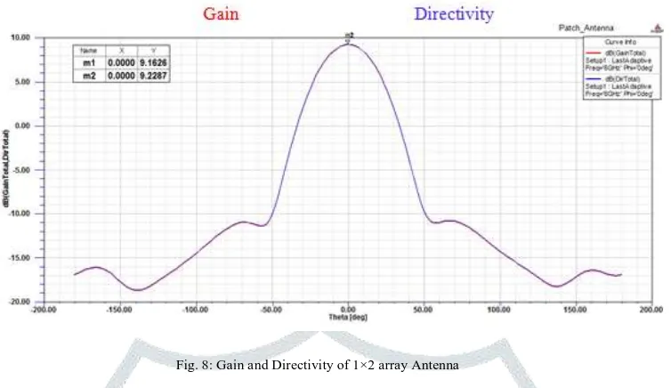
The return loss of 1×2 array antenna is obtained as -19.49 dB at 5.8 GHz frequency shown in Figure 7 and 2D radiation pattern of gain and directivity for 1×2 array antenna is shown in Figure 8. The gain and directivity of antenna obtained as 9.16 dB and 9.22 dB respectively.
JETIR1506063 Journal of Emerging Technologies and Innovative Research (JETIR) www.jetir.org 2046
Fig. 8: Gain and Directivity of 1×2 array Antenna
The return loss of 1×4 array antenna is obtained as -21.12 dB at 5.8 GHz frequency shown in Figure 9 and 2D radiation pattern of gain and directivity for 1×4 array antenna is shown in Figure 10. The gain and directivity of antenna obtained as 11.65 dB and 11.74 dB respectively.
Fig. 9: Return Loss of 1×4 array antenna
JETIR1506063 Journal of Emerging Technologies and Innovative Research (JETIR) www.jetir.org 2047 C.Microstrip Phased Array Antenna
When there is no phase difference between the antenna elements, radiation pattern is shown in Figure 11, zero degree tilt. In order to tilt the beam angle 2 degree to the right, phase difference of 8.29 degree using equation (1).
Fig. 11: Beam steering of array antenna at 20
In order to tilt the beam angle 4 degree to the right, phase difference of 16.57 degree using equation (1). This is shown in Figure 12.
Fig. 12: Beam steering of array antenna at 40
In order to tilt the beam angle 6 degree to the right, phase difference of 24.83 degree using equation (1). This is shown in Figure 13.
JETIR1506063 Journal of Emerging Technologies and Innovative Research (JETIR) www.jetir.org 2048 Now the phase difference of each individual element is shown in below Table 2.
Table 2: Relative Phase of Individual element to A0
A0 A1 A2 A3
0 8.29 16.57 24.83
IV.CONCLUSION
In this work, four element microstrip phased array is designed and simulated. From the result analysis, conclusion is that single patch antenna design gives a return loss of -14.04 dB. Gain of 7.38 dB, at 5.8 GHz while 4 patch array antenna design gives a return loss of -21.12 dB. Gain of 11.65 dB, at 5.8 GHz. Thus there is an increase in gain by factor 2 with increase in array elements. Here main beam of array antenna is tilted 60 without using phase shifter and directivity of the array antenna is increases with the increase in number of elements. So there is linear relation between number of elements and directivity. Thus proposed antenna is used in RADAR and Communication.
V.ACKNOWLEDGMENT
I would also like to express my special gratitude and thanks to Prof. Kush Parikh, Ass. Prof. E&C. department, Indus University, Ahmedabad.
REFERENCES
[1] Merrill I. Skolnik, “Introduction to RADAR systems, 3rd Edition”, Tata McGraw Hill book company, 1981, pp. 278-280.
[2] C. A. Balanis, “Antenna Theory: Analysis and Design, 3rd Edition”, John Wiley and Sons, Inc., 2005, pp. 65-80.
[3] Ab Wahab, N.; Bin Maslan, Z.; Muhamad, W.N.W.; Hamzah, N., "Microstrip Rectangular 4x1 Patch Array Antenna at 2.5GHz for WiMax Application," Computational Intelligence, Communication Systems and Networks (CICSyN), 2010 Second InternationalConference on , pp.164,168, 28-30 July 2010.
[4] Thakur, S.; Narkhede, S.S.; Bhuiya, T., “Microstrip patch antenna array for Rainfall RADAR,”Computing, Communications and Networking Technologies (ICCCNT), 2013 Fourth InternationalConference on, vol., no., pp.1, 4, 4-6 July 2013.
[5] Md. Bakhar, Vani R. M. & P. V. Hunagund, “Microstrip Linear Phased Array for Smart Antenna Application,” International Journal of ElectronicsEngineering, 4 (1), pp. 39– 42, 2012.