Abstract—Purpose of present work is to investigate the effect of oxide flux on welding of austenitic stainless steel 304L plates having thickness 8 mm its effect on welding distortion, ferrite number, hardness value and depth of penetration. SiO2
is used as a flux in the form of powder mixed with the acetone and applied on bead plate without making a joint preparation and without addition of filler wire. The result showed that this technique can increase depth of penetration and weld aspect ratio resulting in lower angular distortion. The ferrite content in the weld joint obtained is 14% by weight; the increase in the ferrite content is due to assistance of flux in rapid cooling therefore more ferrite content in 304L weld metal during the solidification after welding. Finite Element analysis of plate has been carried out using SYSWELD. Three dimensional double ellipsoidal (Goldak) heat source is used to model the heat flow during the welding. the heat source definition has been validated against the experimentally obtained grain structure (macrograph) and thermal history. Finally transient thermal analysis of welded plate has been done for study the peak temperature reaching in flux coated GTA welding.
Index Terms—Active flux, GTAW, austenitic stainless steel, distortion, ferrite, heat source fitting, SYSWELD.
I. INTRODUCTION
In nuclear fusion area welding is most common method of joining. The metal using one of the other among electric arc, laser, plasma arc and electron beam are used widely. A lot of research is going on in these areas in order to make processes more effective, but the fact remains imperative to continue to develop these techniques and especially for better understanding of all phenomena, which occur during welding. Although welding robots and other automated systems are realization of increasing efficient and replaceable welder as only capable of adapting to all factor that disrupt the successful completion of weld.
Among all welding processes GTAW (Gas Tungsten Arc Welding) or TIG (Tungsten Inert Gas) is appropriate candidate for industrial application due to its high delicate achievement qualities. The GTAW is thus a method of choice in industries as diverse as nuclear, aerospace, and pharmaceutical and food processing. Indeed beyond 3 mm it is necessary to perform edge preparation (chamfer) and adding filler material by multi pass welding [1]-[3]. This is due to low yielded arc centrifugal convection current which unfavorable for high penetration weld. Increasing number of pass of welds increase the risk of defects and heat affected zone increases making it slow and unproductive compared
Manuscript received January 9, 2013; revised July 13, 2013.
M. Zuber and V. Chaudhri are with the Institute for Plasma Research Gandhinagar Gujarat India (e-mail: zuber@ipr.res.in).
V. K. Suri and S. B. Patil are with Bhabha Atomic Research Centre Mumbai India.
with other process like MIG process.
Austenitic stainless steel has a large range of successful applications in nuclear due to its high corrosion resistance, high strengths. GTA welding is one of the most common welding processes used for stainless steel. However, comparing to other arc welding processes, this kind of process has drawbacks, such as shallow penetration and low deposition efficiency [4]-[5].
Since last so many years, researchers have focused on improvement in TIG process, one of the emerging method is FCGTAW (Flux Coated GTA Welding). FCGTA welding is a welding in which a thin layer of fine flux coating on the surface of the base material before welding and thus greatly increasing weld penetration with good mechanical properties. But most investigation carried out mainly for carbon steel, titanium and stainless steel, the investigation specifically for 304L alloy was relatively less [6]-[10].
II. EXPERIMENTAL WORK
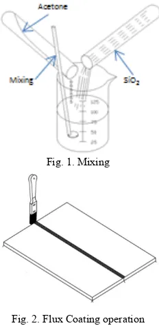
Austenitic stainless steel 304L plates made by machining process in to rectangular 90 mm × 85 mm. the chemical composition of plate is as given below in Table I. Plates were roughly polished with flexible abrasive paper to remove surface impurities, and then cleaned with acetone.
Fig. 1. Mixing
Fig. 2. Flux Coating operation
TABLE ICHEMICAL COMPOSITIONS AND MECHANICAL PROPERTIES
c Si Mn P S Cr Ni Yield UTS u
0.03 0.5 2 0.045 0.03 18 8 400 586 0.3
SiO2 is used as a flux in the form of powder mixed with
Effect of Flux Coated Gas Tungsten Arc Welding on 304L
acetone and made in the form of paste as shown in Fig. 1. A brush was used to apply the mixture on the joint surface to be welded. A layer less than 0.6 mm thick was applied to the surface of the joint to be welded before GTAW shown in Fig. 2. The average coating density was 8 mg/cm2. Soon after application, the acetone evaporates leaving a desired flux layer around the joint. Welding was done without making joint preparation and without addition of filler wire, by just keeping plate side by side or square joint. GTA weld was performed using DCEN (Direct Current electrode negativity), Welding operation was performed with weld torch standard tungsten electrode (3.2 mm diameter) was used. The electrode tip was a blunt point with a 60o include angle. Welding parameters used in the present work is given below in Table II.
TABLE IIWELDING PARAMETERS FOR WELDING EXPERIMENTS
Sr. No. Parameter Value
01 Welding current 190 A
02 Travel speed 180 mm/min
03 Arc length 2.5-3.5 mm
04 Shielding gas Argon
05 Gas flow rate 10 L/min
III. THEORIES OF ACTIVE FLUX WELDING
Flux coated GTA welding was first introduced by the EO Paton Institute in 1950. The first published paper described the use of the fluxes for welding titanium alloys and the first application of flux coating for steels was in 1968 [11]-[12]. Based on literature survey different theories were mentioned.
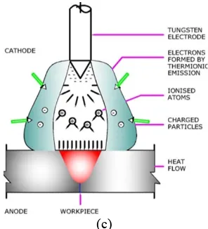
The direction of fluid flow in the molten pool can affect the weld geometry. The temperature coefficient of surface tension is a factor, driving the direction of fluid flow in the molten pool. For GTAW without flux the surface tension will be greatest at the edge of pool and lowest in the centre therefore fluid flow will be outward and weld will be shallow and wide. The addition of oxide flux changes the temperature dependence surface tension and it will be higher at centre and lower at pool causing fluid flow will be inward towards the centre producing narrow and deep penetration that is called Marangoni effect [13]. The oxide and flourine molecules are present in the activating fluxes, which have affinity to chain the free electrons at the edge of the plasma of the arc. It is well known that ions formed this way have substantially lower mobility than the free electrons. This leads to increase current density in the centre of the arc by means of the higher movement of the free electrons. By resulting better focus of the arc the deeper penetration is achieved [14]. The activating flux decreases the surface tension of the weld pool which makes able the arc pressure to cause a deeper invading in the pool. This helps the arc pressure to reach a deeper penetration [15]. The deep penetration by the means of the higher electric insulation of the activating fluxes. Due to this, the arc is able to break through the surface only at a narrower area, which leads to higher current density in the arc spot results the deep penetration [16].
IV. WELD APPEARANCE
Fig. 3 shows the surface appearance of 304L welds produced without flux and with different fluxes. Fig. 3 (a) shows the results of normal GTAW, which shows clean and smooth surface. With FCGTAW surface is rough and some slag is there as shown in Fig. 3 (b). It should be mentioned that the rough surface tends to increase the risk of both corrosion and product contamination.
(a) Without SiO2
(b) With SiO2
Fig. 3. Effect of SiO2 on weld appearance
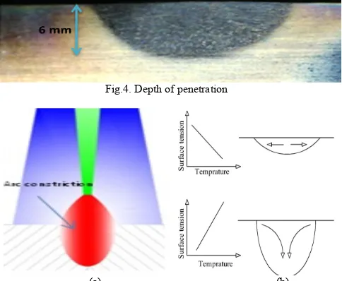
V. EFFECT OF SIO2 ON DEPTH OF PENETRATION Fig. 4 shows result in terms of the depth of penetration obtained with SiO2 GTAW is up to 6 mm which is 200% more than autogenous welding. When using FCGTAW, physically constricting the plasma column and reducing the anode spot, and tends to increase the energy density of the heat source and electromagnetic force of the weld pool, resulting in a relatively narrow and deep weld morphology compared with the conventional GTAW as shown in Fig. 5 (a). Arc constricting also contribute in high depth of penetration as shown in Fig. 5 (c) basic mechanisms. Another reason behind the deep penetration is change surface tension due to flux which changes flow pattern and current, arc length, welding speed was kept constant as shown in Fig. 5 (b). During welding with Flux coated plate voltage required was high as compared to without flux plate welding. Fig. 6 shows the characteristics of weld geometry with SiO2 at four different position .The increases in weld depth is significantly high depth to width ratio as compared to normal GTAW. This increased in depth of penetration and reducing in width is due to arc constriction and marangoni flow.
Fig.4. Depth of penetration
(c)
Fig. 5. Mechanism behind high depth of penetration
VI. WELDING DISTORTION
Localized heating through thickness during welding causes non uniform thermal distribution. As per theory of solidification shrinkage the top surface of the plate shrinks more than the back of plate, which will result in a non uniform thermal stress distribution. If tensile stress at the top surface and the compressive stress at the back surface exceed the yield stress an angular distortion will be expected. Welding distortion occur when non uniform thermal shrinkage in the thickness direction causes angular change nearer to weld line it depends upon various factor penetration, width etc.
Without flux with flux
Fig. 6. weld geometry characteristics
Fig. 7. Welding Distortion measurement
Fig. 8. Angular Distortion
Fig. 7 is a schematic diagram of welding distortion measurement. Before welding surface level was checked at different position. Welding was done by fixing on plate and
change in level of second plate was measured. During the measurement, the stage was moved along the x-axis and a vertical displacement Z was obtained. The angular distortion value calculated from the (1)
θ
= tan
-1x/z
(1) Finally, five different positions on either side of the welds were averaged, and then added together to give the angular distortion value [9]. Fig. 8 shows the distortion in plate after welding. The value obtained from GTAW process is 3 mm which is less as compared to FCGTAW welding, which is 5 mm.VII. FERRITE NUMBER AND MICROSTRUCTURE
Ferrite number is a standard value for designating the ferrite content within an austenitic stainless steel. The ferrite number was measured using ferritoscope a calibrating magnetic instrument. To minimizing errors five reading were noted at different position and an average value was recorded. An average ferrite number was 15% by weight which is generally high due to addition of oxide during welding. Fig. 9 shows welding structure at the centre of plate which is having highest ferrite content, whereas without flux welding the ferrite number is 10 % by weight. Compared to conventional GTAW the FCGTAW is having high energy density of heat source therefore result in lower heat input and faster cooling rate causing high ferrite [17]. The microstructure at the centre of joint is shown in Fig. 10 with FCGTAW process, it shows presence of secondary cracks due to high content ferrite structure.
(a) (b) (c) Fig. 9. Weld morphology (a) 160X (b) 40X (c) 20X
VIII. HARDNESS TESTING
Hardness value was recorded at welded and nearer to joint at four different positions. Due to heating process value of hardness at the joint was 118 BN and in HAZ (Heat Affected Zone) it was 114 BN and away from the joint was decreasing up to 98 BN.
IX. THERMAL ANALYSIS
dimensional finite element mesh model as shown in Fig.10 is used for the FE analysis. This model consists of 15300 brick elements and 20720 nodes. 2D mesh is used for creation of heat source fitting for the thermal analysis. The material database is created based on the temperature related thermo-physical and mechanical properties of the material are taken from literature [18]. The double ellipsoidal heat source parameters are obtained by the iterative manner. The obtained heat source is adjusted and saved in the function database for the use of weld wizard. After obtaining the heat source parameters for the simulation, final FE simulation is carried out using SYSWELD and the results are obtained.
Fig. 10. Three dimensional finite element model meshes.
A. Heat Source Fitting
The heat source fitting tool (HSFT) is available in the SYSWELD, which enables the user to calibrate heat source parameters to perform a steady-state thermal analysis of the welding process. The steady-state analysis completes the analysis in a shorter time. Due to which the user can calibrate the heat source by adjusting the heat source parameters in an iterative manner. The double ellipsoidal parameters describing the heat source are adjusted iteratively until the HSFT produces a fusion zone similar to the one obtained in a macrograph of the experiment. According to the analysis the double ellipsoidal heat source is used for flux coated GTA welding thermal analysis and the heat source fitting analysis is carried out using the meshed model shown in Fig. 11.
The heat input distribution will determine the shape of the weld pool. A double-ellipsoidal heat source is used in this FE simulation because it has found to be the most appropriate model for simulating TIG welding process. This heat source model is also known in the literature as Goldak’s heat source after its inventor name. The heat from the welding arc is applied as a double ellipsoidal heat source proposed by Goldak [19]. It is represented by the (2).
, , , 6√3
√
/ / /
(2)
, , , √
√
/ / /
(3) where ff and fr are parameters of the fractions of the heat deposited in the front and rear ellipsoid, and a1, a2, b and c are the ellipsoidal heat source parameters. Q is the arc heat
input (Q = ηVI), where η is the efficiency which is fixed at 75% and V and I are the arc voltage and current, respectively. The initial temperature is set at 26ºC. The heat loss due to convention and radiation are considered in the thermal analysis. The melting point temperature of the material is 1440ºC and heat effected zone temperature is 750ºC.
The HSFT in SYSWELD is available in three predefined parameterized heat sources of various sizes and shapes (2D Gaussian, double ellipsoidal and 3D conical Gaussian), which can be selected from the default heat source database. The results obtained in the form of adjusted heat source are saved to a functional database for thermal analysis in the welding wizard.
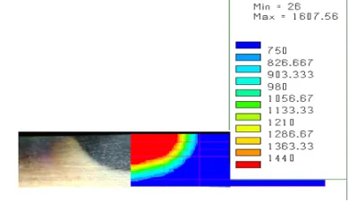
Fig. 11 shows the cross section of the plate welding profiles obtained through FE simulation and experimental at current 190 A, voltage 15.4 V and 3 mm/s. The percentage of error is 2.8% in depth of penetration of FE simulation profile and experimental profile, and the percentage of error in bead width of FE simulation profile and experimental profile is 1.6%. As the current increases both the depth of penetration and bead width are increases, as the current increases then the heat input increases therefore depth of penetration and bead width increases. As the torch speed increases then depth of penetration and bead width decreases as torch speed increases low heat input to base material therefore the depth of penetration and bead width decreases.
Fig. 11. Thermal analysis of Experimental weld bead
B. Thermal Analysis of Butt Plate
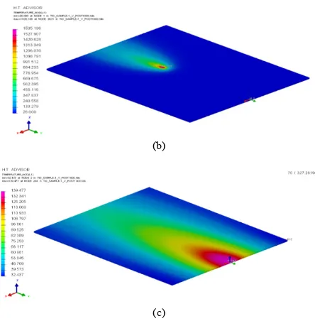
The FE simulation is run for a time period of 800 s. The temperature distributions obtained at various time periods are shown in Fig. 12 (a) - (c) respectively. The time period of 800 s is chosen to allow for the complete thermal analysis to occur, including heating and subsequent air cooling. Fig. 7 (c) shows the temperature distribution at 800 s. It is observed that the maximum temperature reached during the entire thermal analysis is about 1835ºC.
(b)
(c)
Fig. 12. Temperature distribution at 20 s (a), 240 s (b) and 800 s (c)
X. RESULT
The increase in the Depth of penetration obtained with FCGTAW process, which is 200% more than normal GTAW process. Weld depth to width ration was more significant. Ferrite number was increased due to addition of oxides. Hardness value increased due to high temperature at the joint.
Welding distortion during autogenous welding was more whereas with the application of flux the angular distortion seems to be reduced. This phenomenon is related to the size of the HAZ and penetration. With wide and shallow the thermal stress is uniform causing smaller angular distortion. Heat source fitting has been shown a good agreement with experimental result. Maximum peak temperature obtained by thermal analysis is 1835ºC.
REFERENCES
[1] Y. L. Xu, Z. B. Dong, and Y. H. Wei, “Marangoni convection and weld shape variation in A-TIG welding process” Theoretical and
Applied Fracture Mech, vol. 48, pp.178-186, October 2007.
[2] S. W. Shyu, H. Y. Huang, and K. H. Tseng, “Study of performance of stainless steel by A-TIG weld” Journal of Material Engg. Perform.
vol.17 no.2, p. 193-201, April 2008.
[3] H. Fujii, T. Sato, S. P. Lu, and K. Nogi, “Development of an advanced A-TIG (AA-TIG) welding method by control of Marangoni convection” Material Science Engg, vol. 495, pp. 296-306, November 2008.
[4] Y. Huang, D. Fan, and Q. H. Fan, “Arc welding of structural pipe”
Welding Journal, vol.3, pp. l0-24, Feb 2004.
[5] H. Y. Huang, S. W. Shyu, K. H. Tseng, and C. P. Chou, ''Effects of the Process Parameters on Austenitic Stainless Steel by TIG-flux Welding'' J. Mater. Sci. Technol, vol. 22, no. 3, pp 367-373, June 2008.
[6] A. Rodrigues and A. Loureiro, “Effect of shielding gas and activating flux on weld bead geometry in tungsten inert gas welding of austenitic stainless steels”Science and Technology of weld joint, vol. 10, pp 760-7765, December 2005.
[7] S. Leconte, P. Paillard, P. Chapelle, and G. Henrion, “Effect of oxide fluxes on activation mechanisms of tungsten inert gas process” Sci.
and Technology of welds Joint, vol. 11, pp, 389-397, July 2006.
[8] M. Liu, Z. D. Zhang, and G. Song, “Mechanism and Microstructure of Oxide Fluxes for Gas Tungsten Arc Welding of Magnesium Alloy”
Metallurgy and Material Trans. A, vol. 38, pp. 649-658, March 2008.
[9] L. Liu and H. Sun, “Study of flux assisted TIG welding of magnesium alloy with SiO2 particles in flux,” Mater. Res. Innovat,
vol. 12, pp. 47-51, March 2008.
[10] T. S. Chern, K. H. Tseng, and H. L. Tsai, “Study of the characteristics of duplex stainless steel activated tungsten inert gas welds," Material
and Design vol. 32, pp. 255-263, June 2010.
[11] S. M. Gurevich and V. N. Zamkov, "Welding titanium with a non-consumable electrode using fluxes," Automatic Welding, vol.19, pp. 13-16, June 1966.
[12] A. M. Makara, B. N. Kushnirenko, and V. N. Zamkov, "High-tensile martensitic steels welded by argon tungsten arc process using flux,"
Automatic Welding, pp.78-79, July 1968.
[13] Heiple and Roper, "Mechanism for minor element effect on GTA fusion zone geometry," Welding Journal, vol. 61, pp. 97-102, Jan 1982.
[14] Simonik, ''The effect of contraction of the arc discharge upon the introduction of electro negative elements,” Welding Production, vol.23, pp. 49-58, October 1976.
[15] M. M. Savitskii and G. I. Leskov, ''The mechanism of the effects of electrically negative elements on the penetrating power of an arc with a tungsten cathode,'' Journal of Material science vol.9, pp.17-28, Jan 1980.
[16] T. Tanaka, Shimizu, H. Terasaki, M. Ushio, F. Koshi, and C. L. Yang, “Effects of Activating Flux on Arc Phenomena in Gas Tungsten Arc Welding,” Science Technology Weld. Joining, vol. 5, pp 397-402, December 2000.
[17] K. H. Tseng and C. Y. Hsu “Performance of activated TIG process in austenitic stainless steel welds,” Journal of Material Process
Technology, vol. 2, pp 503-512, March 2011.
[18] X. K. Zhu and Y. J. Chao. "Numerical simulation of transient temperature and residual stress in friction stir welding of 304L stainless steel,” Journal ofMaterial processing technology, vol.146, pp. 263-274, December 2004.
[19] J. Goldak, A. Chakravarti, and M. Bibby. "A new finite element model for welding heat source,” Metallurgical Transactions B, vol.15, pp. 299-305, June 1984.
Mohammed Zuberuddin completed his Diploma in Mechanical engineering from Govt. Polytechnic Nanded Maharashtra India in 2003.he received the BE degree in Mechanical Engineering from DR BAMU University Aurangabad India. He completed his Master Degree in Machine Design and Analysis from National Institute of Technology (NIT) Rourkela Orissa India. He is now a research scholar at Institute for Plasma Research Gandhinagar India. His area of work is welding and computation simulation of joining process.
Vilas Chaudhri is a scientist at Institute for Plasma Research. He published number of papers in nuclear Fusion and design journal and other national and international journals. His working area is fusion safety and remotely handling system for nuclear fusion. He is Head for Fusion Safety and Remote handling section for Indian TBM.
V. K. Suri is outstanding scientist at Bhabha Atomic Research Centre Mumbai. He published more than 50 papers in Precision engineering. Currently working as a Head of Division Precision Engineering Division at BARC Mumbai. He is a professor and guide for PhD student at HBNI DAE University at Mumbai and M-tech and PhD committee chairman and visiting faculty for IIT Bombay.