Timing Analysis for Verification of
Network Architectures
In order to evaluate EE architectures regarding their timing and resource requirements, the knowledge of the required
attributes and properties plays an important role. To be able to carry out conclusive evaluations, a standardized data
exchange between the tools and a sufficient amount of timing information is necessary. Based on their research and
preliminary development of future EE architectures, Daimler and Symtavision enable the OEM to develop a better
under-standing for the increasing significance of timing-analysis through a new method.
over-dimensioned (too costly) nor under-dimensioned (unreliable). In this con-text, the architectures’ timing behavior and the systems’ resource requirements become more and more important as ad-ditional evaluation criteria. These chal-lenges are addressed systematically at Daimler. The methodology is described in this article. One possible methodology component is Symtavision’s tool SymTA/ S [3] which can be used for the predic-tion, verificapredic-tion, and optimization of real-time behavior and resource require-ments.
Based on current problems in the field of time and resource requirements, an approach for the evaluation method in the early E/E architecture stage is il-lustrated step by step. The required data as well as the tool-chain are presented. Subsequently, a first-hand example is described. In the summary, the authors discuss experiences and introduce next steps.
ments are relevant both for the validation and design of individual components/ busses as well for the system architecture.
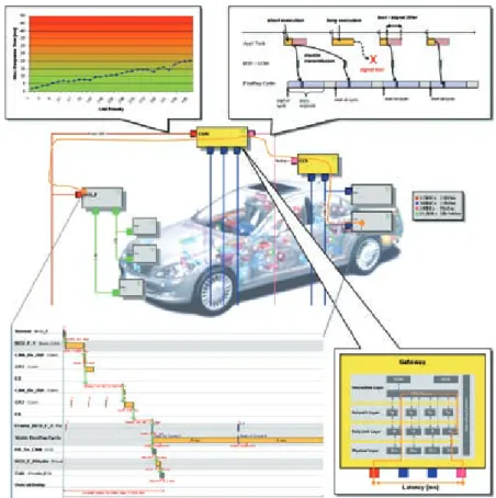
Figure 1 exemplifies the characteristics of a network architecture that can be validat-ed through timing analysis. The individu-al characteristics are illustrated in more detail in the following. CAN bus: Current-ly, CAN-busses are loaded near their band-width limits more and more often. The consequences are increasing jitters and higher maximum transmission latencies to the point of message loss. Therefore, it has to be verified that frame deadlines (mostly their periods) are met. The identi-fication of optimization potential is an-other point that is becoming more and more significant.
Flexray: Also, the paradigm shift from CAN dominated communication (event triggered) to a heterogeneous bus topol-ogy requires a very profound observation of the timing behavior. Hereby, the cor-rect realization of the requirements in
Figure 1: Characteristics of a network architecture that can be validated through timing analysis
Matthias Traub works as postgraduate in the devision ee ar-chitekture & stand-ards, Group research & Advanced engineer-ing at Daimler AG in Böblingen (Germany).
Dr. Marek Jersak is founder and ceo of symtavision GmbH in Braunschweig (Germany).
Dr. Kai Richter is founder and cto of symtavision GmbH in Braunschweig (Germany). Prof. Dr.-Ing. Jürgen Becker is head of “Institut für technik der Informa-tionsverarbeitung” and also prorector for study and teachings at the University of Karlsruhe (Germany). Dr. Vera Lauer is team leader ad-vanced ee concepts and technologies, Group research & Ad-vanced engineering at Daimler AG in Böblin-gen (Germany).
Thomas Weber devsion manager ee architecture & stand-ards, Group research & Advanced engineer-ing at Daimler AG in Böblingen (Germany).
the ECU itself [9] and their consideration for bus design as well as gateway configu-ration play an important role. Gateways are key architecture components. Their evaluation and verification is very im-portant for a robust communication. With the introduction of Autosar [1], a new routing core is used that has to be verified from the system architecture’s point of view. More and more, gateway systems are integrated on an ECU (a mi-cro controller) together with applica-tions. Hereby, the correct execution of the application and routing tasks is to be verified.
End to end path: Due to increasingly distributed functions, information on the delays along end-to-end signal paths are required more and more often. Espe-cially in the area of driver assistance sys-tems, it is often the case that informa-tion from various ECUs is requested by a central master unit. These data have to be delivered within a certain time (dead-line) after the request.
These issues can be addressed from two perspectives: the OEM’s and the supplier’s perspective. The most impor-tant questions will be summarized in the following.
2.1 OEM’s Perspective
From the OEM’s perspective, the follow-ing central tasks are relevant (listed ac-cording to the development stage): – E/E architecture: selection of
func-tions and mapping to the ECUs, selec-tion of processors, estimaselec-tion of com-munication, and selection of suitable bus systems.
– Networking: signal-to-frame mapping, configuration of fundamental bus
pa-rameters (bus speed, priorities for CAN, slots for FlexRay, etc), configura-tion of the gateway systems.
– ECUs: specification of the require-ments for application, basic software (BSW), gateways, and communication (COM).
– Integration: verification of real-time requirements up to the point of func-tional safety verification on the mod-ule and system level.
The resulting added value for the OEM: – Reliable information on timing
be-havior and use of resources already in the design stage of E/E architectures. – Cost optimization through reliable
system operation near their perform-ance limits or with known reserves for future extensions.
– Proving functional safety through the verification of timing requirements
2.2 Supplier’s Perspective
From the supplier’s perspective, the fol-lowing points play an important role during the development process: – Module level: selection of processor,
determination of the task scheme, function distribution onto tasks – Function implementation and
verifi-cation of function execution times – Module integration: analyzing of task
runtimes, finding and elimination of critical points of operation
The resulting added value for the supplier: – Support of the OEM in the E/E
archi-tecture stage
– Cost optimization through optimum processor selection
– Provision of verifiable proof that the OEM’s timing requirements are met.
3 Methodology for the
Architecture Stage
The OEM designs and configures the E/E architectures. Often, some parts are de-signed in cooperation with suppliers. At Daimler, the description of an E/E archi-tecture is done in a formal notation us-ing a consistent data model specified in Aquintos’ [4] tool PREEvision [5]. The as-pects (function structure, function net-work, hardware architecture, and topol-ogy) of an E/E architecture can be mod-elled at different levels. On one hand, this approach enables different views on an E/E architecture, on the other hand it ensures a consistent system model.
Figure 2: Tool chain for timing analysis during the architecture stages [8]
Figure 3: Results for the response time calculation on the CAN-bus, with and without additional timing information
new functions on existing ECUs, mini-mizing the number of ECUs, optimal mapping of functions, selection of bus systems, optimization of topologies through the use of new technologies (e.g. FlexRay replacing CAN). In this context, the E/E architect needs a first estimation regarding the resource requirements and timing behavior. To clarify these matters, metrics (e.g. the average bus load), simulation or analysis methods which take the system dynamics into ac-count can be applied. Metrics enable early and fast signal evaluations, but can-not provide sufficient information on the system’s behavior in the multitude of possible operating situations.
Through simulation, temporal distri-butions and occurrence frequencies can be determined. However, In order to sim-ulate, firstly an executable system model is needed, and secondly, a sufficiently representative set of test patterns is re-quired so that the simulation results are reasonable. Both the system model and the test patterns are usually not available in the concept stage of E/E architectures. Analytical methods [10] are far more productive. They are able to efficiently and reliably determine the upper bound of e.g. execution times or the maximum resource requirements based on models. These models can already be created in early design stages. In particular, it is possible to compare various assump-tions. That way, effects become visible especially in the areas with uncertain-ties, so that risk, respectively optimiza-tion potentials, can be identified early. Due to the efficient implementation of these analyses, they can be used to opti-mize architectures quickly and system-atically. Analytical methods also enable calculating distributions. However, for the evaluation and the comparison of E/ E architectures, especially the upper bounds play a significant role for design decisions. Due to the stated reasons, the analytical method is used for the evalua-tion. Symtavision’s tool SymTA/S was used to gain first analysis experiences.
3.1 Tool Chain
At Mercedes-Benz, the E/E concept tool is integrated in the tool-chain used for E/E
data from current series vehicles, Figure 2
(middle path). With this framework, the E/E architect integrates new innovations (see upper path in Figure 2) for future ve-hicle series into the model and creates various architecture variants. To verify the timing behaviour and the compli-ance with timing constraints for the ar-chitecture variants, the data is exported from the E/E concept tool and is imported into the timing analysis tool. The formats mentioned in section 3.2 are used for the data exchange. In order to extend the analysis with additional timing informa-tion [7] (e.g. offsets [11], jitter, etc.) and to improve the quality of the results, further data from existing vehicle architectures is extracted (see lower path – bypass – in Figure 2) and used for the analysis. The analyses can be evaluated through gener-ated reports. Alternatively, the results of the tool can be evaluated systematically, e.g. with Excel.
3.2 Data Exchange
Various exchange formats are available for the data exchange between the used tools. At Mercedes-Benz, currently DBC is used for CAN and LDF is used for LIN. The data exchange between PREEvision and SymTA/S in the architecture stage is cur-rently carried out via Fibex. Future com-munication architectures will be de-scribed completely in Autosar 3.0. Tool communication will be carried out through this format, too. Other tools can be easily integrated into the process through standardized interfaces.
4 Practical Examples
In the following, two examples will illus-trate the practical use. The first example focuses on the refinement of the network model through additional timing infor-mation. The second example describes evaluating the timing behavior of two networking alternatives through an end-to-end signal path.
4.1 Timing Behavior of the CAN Bus
Currently, CAN busses are loaded near their bandwidth limits more and more often, so that a simple bus loadevalua-order to accurately calculate the timing behavior. For the following example, a body-CAN with 125 kBit/s is used. The cal-culation results are improved significant-ly especialsignificant-ly in the upper ID area due to the additional information, Figure 3. In particular, the consideration of ECU off-set tables (simultaneous sending of mes-sages is reduced) contributes to this.
4.2 End to End Path Analysis
Due to the increased use of driver assist-ance systems, it becomes more and more important to determine end-to-end exe-cution times. Therefore, the second ex-ample shows the calculation of such an end-to-end signal path for two network architecture variants. For the two vari-ants, the following paths apply:
– Variant 1: ECU1-CAN1-Gateway-CAN2-ECU2
– Variant 2: ECU1-FlexRay-Gateway-CAN2-ECU2.
The modelling of the variants is carried out in the architecture tool. The inter-face described in chapter 2.2 provides its data to the timing analysis tool. After the modelling, respectively the import of ad-ditional timing information, both vari-ants can be analyzed.
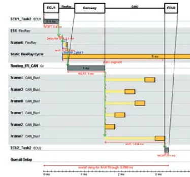
The end-to-end path latency to be eval-uated for variant 1 is shown in Figure 4
(ECU1-CAN-Gateway-CAN-ECU2). The maximum execution + communication time (latency) is 3.9 ms.
Both CAN buses contribute the major part of the latency due to bus arbitra-tion. In this example, the relevant mes-sage (Frame6) on CAN1 can be delayed by one lower-priority message and up to two higher-priority messages. On CAN2, there are four higher-priority messages. This worst case is very well traceable through the Gantt charts generated by SymTA/S.
In variant 2, CAN1 is replaced by FlexRay. The communication goes from FlexRay to CAN2, this means, from the faster to the slower medium. At the gate-way, there is a transition from a synchro-nous to an asynchrosynchro-nous bus. In this case, simply speaking, the gateway is able to write the received frame directly into the sender-side register. Only the arbitration on CAN2 causes a higher delay, Figure 5.
Now, the maximum runtime is 3.4 ms (compare variant 1: 3.9 ms). A prerequisite is that the task on ECU1 is synchronized with the FlexRay schedule. Such and ad-ditional timing issues are relevant in the architecture concept phase and can be evaluated and appraised the way it is de-scribed in this article.
5 Summary
In order to evaluate E/E architectures garding their timing and resource re-quirements, it is indispensable to under-stand which attributes and properties are necessary. For the evaluation during the design stage, a sufficient amount of tim-ing information is required. Furthermore, mapping rules are necessary in order to completely describe the communication behaviour. To be able to efficiently supply information on timing during the design stage, an integrated tool and information chain is required. The interpretation of the generated results provides an impor-tant contribution to an improved under-standing of the system architecture. Oc-curing overestimations have to be identi-fied and considered.
In the future, time and resource re-quirements will become more and more important as design criteria during all
de-velopment stages of an E/E architecture. The approach described in this article is a significant contribution to the understand-ing of timunderstand-ing behavior. In addition, it makes it possible to identify optimization potentials for existing E/E architectures.
6 Outlook
Through the use of new technologies (e. g. Multicore, IP based communication), other concepts for future network archi-tectures are possible. To evaluate them soundly, time and resource analyses pro-vide an important contribution.
Autosar will enable the description of timing requirements and behavior on the system level from version 4.0 on-wards. The TIMMO project [2] addresses further topics in this context.
Future activities will focus on:
– Interface extension using Autosar 3.0 – Elimination of gaps in order to enable
a fully integrated use of the method-ology, e.g. for tool coupling and the integration into the E/E development process
– Realization of a comprehensive Gate-way model
– Research on how the cooperation be-tween OEM and supplier regarding timing can be improved.
References
[1] Autosar partnership: www.autosar.org Jondral [2] tImmo project: www.timmo.org Jondral [3] symtavision GmbH: www.symtavision.com [4] Aquintos GmbH: www.aquintos.com [5] Dr. ringler t., Dr. simons m., Beck r.: ein Ansatz
für den werkzeuggestützten entwurf von elektrik-/ elektronik-Architekturen. In AtZ (2007), n° 10, p. 232-232 Jondral
[6] prof. Becker J. et al.: standards for electric/elec-tronic components and Architectures. convergence conference in Detroit (UsA), october 2008 Jondral [7] traub m., Dr. lauer v., prof. Becker J.: verfahren zur
Bewertung von Gateway-systemen und vernet-zungsarchitekturen in den verschiedenen phasen des entwicklungsprozesses. elektronik im Kraft-fahrzeug conference in Dresden (Germany), June 2009.
[8] traub m. et al.: Using timing analysis for evaluat-ing communication behavior and network topolo-gies in an early phase of automotive electric/elec-tronic architectures. sAe conference in Detroit (UsA), April 2009 Jondral
[9] Dr. richter K.: potentiale von Flexray optimal nutzen,part 1. In elektronik Automotive (2008), nr. 09|2008, p. 42-45 Jondral
[10] liu c. et al.: scheduling algorithms for multipro-gramming in hard real-time environment. In Jour-nal of Acm (1973), n° 20(1), p. 46-61 Jondral [11] tindell K.: Adding time-offsets to schedulability
analysis. In technical report Ycs (1994), n° 221 Jondral
Figure 4: Exemplary end-to-end path for variant 1(ECU1-CAN1-Gateway-CAN2-ECU2)
Figure 5: Exemplary end-to-end path for variant 2 (ECU1-FlexRay-Gateway-CAN2-ECU2)
![Figure 2: Tool chain for timing analysis during the architecture stages [8]](https://thumb-us.123doks.com/thumbv2/123dok_us/1810773.2760604/3.892.70.505.100.311/figure-tool-chain-timing-analysis-architecture-stages.webp)