Mediated Reality using Computer Graphics Hardware for Computer Vision
James Fung, Felix Tang and Steve Mann
University of Toronto, Dept. of Electrical and Computer Engineering
10 King’s College Road, Toronto, Canada,
fungja, mann
@eecg.toronto.edu, [email protected]
Abstract
Wearable, camera based, head–tracking systems use spatial image registration algorithms to align images taken as the wearer gazes around their environment. This allows for computer–generated information to ap-pear to the user as though it was anchored in the real world. Often, these algorithms require creation of a mul-tiscale Gaussian pyramid or repetitive re–projection of the images. Such operations, however, can be computa-tionally expensive, and such head–tracking algorithms are desired to run in real–time on a body borne com-puter. In this paper, we present a method of using the 3D computer graphics hardware that is available in a typical wearable computer to accelerate the repetitive image projections required in many computer vision al-gorithms. We apply this “graphics for vision” technique to a wearable camera based head–tracking algorithm, implemented on a wearable computer with 3D graphics hardware. We perform an analysis of the acceleration achieved by applying graphics hardware to computer vi-sion to create a Mediated Reality.
1
Introduction
Motion estimation and image registration algorithms often use repetitive or iterative schemes to determine motion between images. At each iteration or repetition, such algorithms often require the image to be warped, and this warped image is then used as the input to the next stage of processing. Additionally, multi-scale Gaussian pyramids may need to be created, and image filtering and down sampling may be required. Since the image warp will typically not result in pixels be-ing mapped exactly to other pixel locations, some meth-ods of interpolation are required. The process of image warping can often be computationally intensive, and ac-curate filtering and interpolation techniques add to the computational complexity of the image warp. Many
vi-sion algorithms, however, are desired to run in real–time, and the time spent re–warping and filtering the images can make up a large portion of the calculations required on each frame.
Many current graphics cards incorporate a great deal of hardware specifically designed to achieve extremely fast real–time rendering of texture mapped polygons. Additionally, high–end graphics cards incorporate hard-ware designed for filtering and pixel interpolation to cre-ate accurcre-ate texture maps. Many modern graphics cards are capable of hardware bilinear filtering and anisotropic filtering (though the specification of anisotropic filter-ing varies greatly between different graphics cards). The process of displaying a texture mapped polygon is essen-tially the same as applying a projective coordinate trans-formation to an image. This suggests that it is possible to utilize the hardware of modern graphics cards to ap-ply a projective coordinate transformation in hardware, rather than doing so in software. In particular, graph-ics cards are tuned to create perspective projections of planar surfaces. When an image is texture mapped onto this planar surface, the graphics hardware will project the image onto the surface, which is a type of image warping (under projection).
In order to achieve fast, real–time computer vision algorithms, specialized hardware has, in the past, been used. In [4], a general purpose array of FPGAs was used to achieve face recognition at camera frame rates. While similar hardware could be developed for image warp-ing, such hardware is already incorporated into modern graphics cards. It is thus possible to use existing, low cost and easily available graphics cards to realize ware acceleration. In this way, computer graphics hard-ware, which is most commonly used to project computer generated information into an image (image synthesis), is rather being used for the purpose of accelerating a computer vision algorithm (image analysis).
START WITH IMAGE PAIR, g AND h
CONSTRUCT AN IMAGE PYRAMID FOR EACH OF g AND h
INITIALIZE PARAMETERS TO THE IDENTITY AND INITIALIZE RESOLUTION INDEX TO LOWEST RESOLUTION DESIRED
ESTIMATE PARAMETERS, q, OF APPROXIMATE MODEL RELATING IMAGES AT CURRENT RESOLUTION LEVEL
CONVERT PARAMETERS, q, OF APPROXIMATE MODEL TO PARAMETERS, p, OF EXACT MODEL
COMPOSE PARAMETERS, p WITH PREVIOUS PARAMETERS
APPLY COMPOSITE PARAMETERS TO ORIGINAL h TO BRING IT CLOSER TO TARGET g
IS h CLOSE ENOUGH TO g ? APPLY COMPOSITE PARAMETERS TO ORIGINAL COMPARISON IMAGE AT CURRENT RESOLUTION LEVEL INCREMENT RESOLUTION LEVEL INDEX YES YES NO NO IS FINAL DESIRED LEVEL REACHED ? END
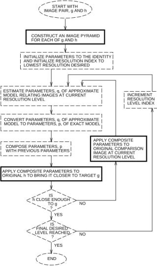
Figure 1: The VideoOrbits algorithm. The steps shown in solid dark lines have been accelerated using graphics hardware available on common 3D accelerated computer graphics cards.
2
Experimental Setup
In order to determine the advantages of apply-ing hardware video acceleration for image warpapply-ing, a Mesa3D program was written to access available video hardware. Mesa3D is a library which works identically to OpenGL [8]. Mesa3D is capable of performing per-spective transformations of a plane [3] according to a projection matrix. Such an ability is particularly suited towards the VideoOrbits algorithm.
2.1
VideoOrbits
The VideoOrbits algorithm [7] considers transforma-tions of planar patches as seen by a camera free to pan, tilt, and rotate about its optical axis. VideoOrbits is well suited for applying OpenGL video acceleration because VideoOrbits is a repetitive multiscale algorithm.
Fig-ure 1 shows the VideoOrbits algorithm. The steps of the algorithm which can be accelerated with graphics hard-ware are outlined in bold. From the figure, it can be seen that at each repetition, VideoOrbits attempts to estimate eight parameters of a projective coordinate transforma-tion to spatially register two images. Then, VideoOrbits projects one image accordingly. This projected image is then used as an input to the next repetition of the al-gorithm. The projective coordinate transformation used in VideoOrbits maps straight lines to straight lines at all times, and thus represents a subset of all possible image warps. Thus we refer to image warping in VideoOrbits as projection rather than the more general term of image warping. In OpenGL, this is achieved by the viewing of a plane from different camera angles. In fact, the projec-tive parameters calculated by VideoOrbits can be used as a camera transformation in OpenGL.
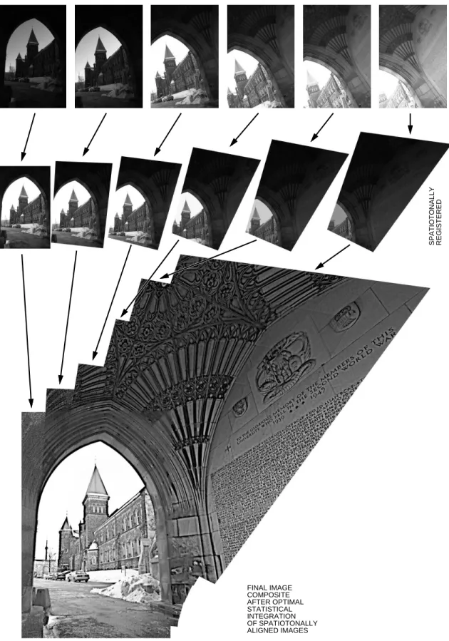
Figure 2 demonstrates VideoOrbits image process-ing. The top row of images shows the original images taken by a camera looking about a static scene. The second row of images shows each of the original ages projected to spatially align with the leftmost im-age. These images are demonstrate the operations car-ried out in the highlighted algorithmic steps of figure 1. Additionally, the images have been comparametrically processed [6] to set their exposures equivalently. Note from the shape of the images that after the VideoOrbits projection, the images appear as projected quadrilater-als. In OpenGL, each of the images is a texture mapped plane, viewed at the appropriate angle. After each of the images has been properly projected, they can each be composited into a single image composite. The image in the third row shows the result of compositing the mulit-ple images of different exposure. This final image is thus of large spatial extent. Furthermore, comparamet-ric statistical methods have also been applied to create an image of greater dynamic range than any of the origi-nal images. The statistical image enhancement methods applied to these images required floating pointing ac-curacy, which is effortlessly accomodated by OpenGL since OpenGL and graphics hardware can work natively with floating point representations of textures.
VideoOrbits has applications for performing camera based head tracking to create a wearable, tetherless me-diated reality [5]. Essentially, the motion of a user’s head as they look around a scene is very similar to the motion of a camera panning, rotating, and tilting about its optical axis. This is to say that motion of the cam-era is induced by motion of the head. VideoOrbits is well particularly suited to describe this prevalent mo-tion in a camera based head tracking system. This is especially useful in Mediated Reality applications to make computer–generated information appear as though
SPATIOTONALLY REGISTERED FINAL IMAGE COMPOSITE AFTER OPTIMAL STATISTICAL INTEGRATION OF SPATIOTONALLY ALIGNED IMAGES
it was affixed to the real world scene as viewed through an HMD or EyeTap [5] devices.
VideoOrbits camera based headtracking has been im-plemented on a high–end server computer and runs at 11 frames per second. However, even faster processing is desirable for more accurate head–tracking, and often, wearable computers do not have as much computational power as their desktop counterparts. Currently the algo-rithm can lose tracking when large motions occur (such as the user moving their head quickly). Faster tracking causes large head motion to be captured by more frames, thus in each pair of frames, the motion appears smaller. This in turn results in greater accuracy for the VideoOr-bits algorithm. Furthermore, by accelerating the image projection, more repetitions of the algorithm can be per-formed on each subsequent image, which in turn yields greater accuracy as well.
To investigate the effect of graphics hardware accel-eration, the OpenGL program was designed to accept projective parameters from the VideoOrbits algorithm, allowing the OpenGL program to be used with VideoOr-bits. In this investigation, the speedup achieved with graphics hardware was examined. This was done by comparing the speed of the software image projection algorithm to the OpenGL image projection program.
2.2
Mapping Projective Coordinate
Transfor-mations
In OpenGL, the most straightforward way of apply-ing the projective coordinate transformation of VideoOr-bits is to consider it to be a transformation to be applied to the projection matrix used in OpenGL.
The operation of applying a projective coordinate transformation to an image is homomorphic 1 to the process of projecting a texture mapped polygon under perspective projection in OpenGL. Thus, hardware ac-celeration of VideoOrbits projective transformations can be achieved by defining an homomorphism between the projective space of VideoOrbits and the projective space and homogeneous coordinate system of OpenGL. An homomorphism is defined by a mapping of VideoOr-bits projective transformations to OpenGL projection matrices :
(1)
In the VideoOrbits algorithm, the projective coordinate transformation (PCT) is written as:
(2) 1homomorphic refers precisely to algebraic homomorphisms, as
discussed in [2] '%( #)%"% *,% -/. #.,%10 2 3 (3)
Thus, it defines an eight parameter space. The trans-formation can be re-written as a46587$5 matrix:
9: " ;% * %( %<% * % . . % =>?9: => x (4)
where it can be seen that the set of projective coordi-nate transformation forms a group acting upon a set@ of image coordinates.
Thus, what is desired is some homomorphism mapping the projective coordinate transformation of VideoOrbits to a4BA 7 A projection matrix in OpenGL.
The desired homomorphism is given by:
DCEGF IHJ 9: < &% * %K %"% * % . .L% =>NMO (5) 9P P : Q '%"% RS'%( *(%UT RS! &% Q ! " #*L #T . % . T T T T =WV V > (6)
where it is now necessary to restrict X " , '%<%Y T . This however, is not a problem since
X " and '%"% represent zoom in the and
directions, and a zoom of
T
has little physical sense. This mapping takes into account the dif-ferent coordinate systems and conventions used by each program. Equation 6 is used as a camera transformation matrix. Thus, it describes the transformation the camera undergoes, such that the plane will appear as required under OpenGL perspective projection.
To perform the image projection in OpenGL, then, the image is first loaded into the OpenGL program as a texture map. The four corners of the image are mapped onto the four vertices of a plane located atZ
. Then, the ‘camera’ in OpenGL is positioned to face this plane. This is achieved by using the
gluLookAt()utility function.
Once the camera is facing the plane, a bounding frus-tum is defined to create a perspective projection. The function callglFrustum()creates a frustum which is used to map a the region which falls inside the frustum into a normalized device coordinate system (NDCS). The resulting framebuffer holds an image which should be close to (if not identical) to the VideoOrbits projec-tion.
To conform exactly with the VideoOrbits programs, the OpenGL program must create a viewing window
which properly bounds the transformed image. In or-der to calculate where the bounds of this viewing win-dow should lie, a normalized frustum projection matrix is created. Then, the desired projection matrix is applied to move the camera appropriately. The four corners of the plane can now be calculated by applying the new projection matrix to each of the four corners. These cor-ners, given in the NDCS for the current frustum, give the maximum bounds for the projected plane. A new frustum, then, can be determined from these NDCS co-ordinates. The new frustum viewing angle remains the same, but the near plane geometry is determined by the desired bounding box. Using this frustum to create the image gives the properly projected and correctly bound image.
2.3
Direct Rendering in GNU/Linux
In GNU/Linux, the hardware is allowed to render di-rectly into the framebuffer via the Direct Rendering In-terface [1] (DRI). DRI allows the video chipset to by-pass the function calls required by the graphical win-dowing system (X-Windows) to display graphics. DRI is required to achieve hardware video acceleration in GNU/Linux.
Once the plane has been projected, the results must be read back from the framebuffer into main memory. This process is known as “readback” [8], and is implemented by the OpenGL function callglReadPixels(). Be-cause graphics cards are not necessarily designed for fast reads from the frame buffer to memory, the read-back time must be included in the timing comparisons of hardware vs. software image projection as it is an im-portant aspect of the hardware rendering scheme being used.
Since DRI renders directly to the framebuffer, the im-age will appear on the screen when rendered. Thus, the OpenGL hardware rendering program requires time to set up the rendering area, and create an X-Window. In an iterative/repetitive motion estimation algorithm, this initial overhead time would be incurred only once, and this setup time would not apply to the further estima-tions.
In order to investigate the effect of hardware on mul-tiple iterations, the display setup time was not timed. The timing information for both the Mesa3D hardware and software programs timed the following:
1. Initialization of the texture mapping the texture onto a plane
2. Calculation of the bounding frustum
3. Positioning of the camera to apply the projective
coordinate transformation on the plane and render-ing of the scene
4. Reading of the pixels from the framebuffer back into memory
The time required to complete these steps is hereafter re-ferred to as the projection times. To get a proper timing for the projection, it must be timed at some point after the image is known to have been rendered. The func-tion call toglReadPixels()is used to read back the image from the framebuffer. It ensures that the image is rendered and this was verified by saving and displaying the buffer which was read back.
3
Results
To determine the speed–up attained by using hard-ware acceleration, a program using the hardhard-ware accel-eration was compared with the software algorithm. A set of projective coordinate transformations was generated according to the equations of [9]. The programs were run on a wearable computer with a 700 MHz Pentium– III processor, with 64 MB of RAM. The wearable com-puter had an Intel i810 graphics chipset. Additionally, the programs were run an a more powerful desktop com-puter which had a Nvidia GeForce2 GPU to investiage the speedup achieved by more powerful graphics pro-cessing.
Figure 3 shows the results of timing a single projec-tion using three methods:
1. a program using Mesa3D and available computer graphics hardware and DRI (ran on both the i810 and the GeForce2)
2. a program using Mesa3D, using software algo-rithms
3. a program running the equivalent VideoOrbits al-gorithm
Thus, an additional program is discussed here, which uses the software implementation of Mesa3D (actually the Mesa3D program is the same as the DRI program, with the direct rendering turned off). The software Mesa3D was examined because it is considered to be well optimized code for computer graphics applications. Thus, computer vision algorithms can also benefit from the speed and optimizations used in computer graphics software. So on machines which may not benefit from 3D graphics acceleration, Mesa will still implement an optimized software projection, and additionally this was examined.
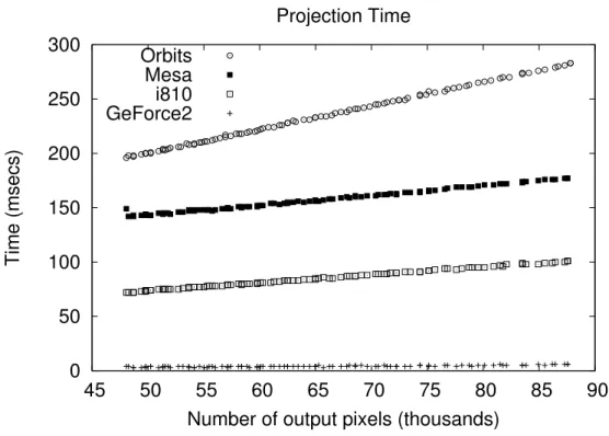
Figure 3: Projection times for VideoOrbits software, Mesa3D (using software rendering) and Mesa3D with DRI hardware rendering enabled.
For the plot of figure 3, the input image size was set, and different projection parameters were given to the three different programs, and the time taken to project the image was recorded. The projections used were independent rotations about each of the principle axis, with a maximum rotation of 15 degrees about any axis. From the data, the average speedup between VideoOr-bits using DRI vs. using the CPU was . The av-erage speedup between VideoOrbits and the Mesa soft-ware rendering was
and the average speedup be-tween the Mesa software rendering and the DRI imple-mentation was
. This speedup verifies that our DRI implementation did indeed use the available graph-ics hardware. For the Nvidia GeForce2 GPU, it was noted that the first iteration had an extra 10 msec over-head (for a 320x240 size texture), possibly due to a tex-ture cache miss on the initial projection. Subsequent it-erations took between 5-8 msecs.
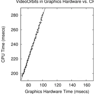
Figure 4 shows the effect of hardware acceleration on input images of different sizes, on the wearable com-puter. For this figure, the projection parameters were held constant, and the input image size was varied. In all cases, the hardware accelerated program projected the image faster than VideoOrbits. The smallest image size was and the largest input image size was
. The slope of a linear best fit line through the plot is . Thus, for this range of input image sizes,
the hardware speedup was .
Figure 5 shows the effect of different projection pa-rameters on the speed of the projection, on the wearable computer. For this plot, the input image was held con-stant, but the projection parameters were varied. The larger projection times shown correspond with increas-ing numbers of output pixels of the resultincreas-ing image. Thus, this plot is measuring the effects of increased amounts of pixel interpolation, since large ouput images required more pixel interpolation since there were more output pixels. The slope of this graph was
T
. Slope here may be interpreted as how well each of the pro-grams using DRI and the CPU dealt with more interpo-lation being required. Thus, the hardware was able to handle increased amounts of interpolation
T
faster than the VideoOrbits software.
4
Conclusion
We have discussed the use of OpenGL to accelerate the VideoOrbits camera based head–tracking algorithm. VideoOrbits estimates the eight parameters of a projec-tive coordinate transformation to spatially register two frames of video from a camera free to pan, tilt, and rotate about its optical axis. Because this coordinate transfor-mation equivalently describes the projection of a rigid
Figure 4: Projection times for VideoOrbits using graphics hardware vs. the CPU given varying image sizes. All images had identical projection parameters.
planar patch as seen by a camera at an arbitrary angle, VideoOrbits is suitable for hardware acceleration using commonly available 3D computer graphics hardware. In each step of the parameter estimation, VideoOrbits projects the input frames. This projection is equivalent to the viewing of a texture mapped polygon in OpenGL. Thus, the rigid planar patch was treated as a polygon, and the image mapped onto the polygon as a texture. The resulting image, viewed under an appropriately de-fined perspective projection, was then read back from the graphics hardware, and was used by the VideoOrbits algorithm again. This hardware accelerated VideoOrbits algorithm was implemented on a wearable computer, and utilized the on–board 3D graphics chipset. From the timing measurements, it is clear that in all cases the hardware projection outperformed the software projec-tion, generally speeding up image projection by a factor of . The hardware benefit is greater with increas-ing amounts of pixel interpolation. This shows that the hardware can be effectively used to speed up repetitive image registration algorithms.
Acknowledgements
We would like to acknowledge Chris Aimone and Corey Manders for their help.
References
[1] Direct rendering interface. http://dri.sourceforge.net.
Figure 5: Projection times for VideoOrbits programs, one using graphics hard-ware and the other the CPU. The algorithm was given a fixed input image and the projection parameters were varied (resulting in larger output images).
[2] M. Artin. Algebra. Prentice Hall, 1995.
[3] Foley, vanDam, Feiner, and Hughes. Computer Graphics,
PRINCIPLES AND PRACTICE. THE SYSTEMS
PRO-GRAMMING SERIES. Addison-Wesley, second edition, 1990.
[4] R. Herpers, G. Verghese, K. Derpanis, R. McReady, J. MacLean, A. Levin, D. Topalovic, L. Wood, A. Jepson, and J. Tsotsos. Detection and tracking of faces in real environments. In Proceedings of the International
Work-shop on Recognition, Analysis and Tracking of Faces and Gestures in Real-Time Systems, Corfu, Greece, 1999.
[5] S. Mann and J. Fung. Videoorbits on eye tap devices for deliberately diminished reality or altering the visual per-ception of rigid planar patches of a real world scene. In
Proceedings of International Symposium on Mixed Real-ity (ISMR2001), pages 48–55, March 14-15 2001.
[6] S. Mann, C. Manders, and J. Fung. Painting with looks: Photographic images from video using quantimetric pro-cessing. In ACM Multimedia 2002 (to appear in), Juan Les Pins, France, December 1-6, 2002.
[7] S. Mann and R. W. Picard. Video orbits of the pro-jective group; a simple approach to featureless
esti-mation of parameters. TR 338, Massachusetts
In-stitute of Technology, Cambridge, Massachusetts, See http://hi.eecg.toronto.edu/tip.html 1995. Also appears in IEEE Trans. Image Proc., Sept 1997, Vol. 6 No. 9, p. 1281–1295.
[8] J. Neider, T. Davis, and M. Woo. OpenGL Programming
Guide: The official guide to learning OpenGL.
Addison-Wesley, third edition, 1993.
[9] R. Y. Tsai and T. S. Huang. Estimating
Three-Dimensional Motion Parameters of a Rigid Planar Patch I. IEEE Trans. Accoust., Speech, and Sig. Proc.,