FortiGate Enterprise
Version 3.0 MR5
FortiGate Enterprise Configuration Example Version 3.0 MR5
August 28, 2007
01-30005-0315-20070828
© Copyright 2007 Fortinet, Inc. All rights reserved. No part of this publication including text, examples, diagrams or illustrations may be reproduced, transmitted, or translated in any form or by any means, electronic, mechanical, manual, optical or otherwise, for any purpose, without prior written permission of Fortinet, Inc.
Trademarks
Dynamic Threat Prevention System (DTPS), APSecure, FortiASIC, FortiBIOS, FortiBridge, FortiClient, FortiGate, FortiGate Unified Threat Management System, FortiGuard, Antispam, FortiGuard-Antivirus, FortiGuard-Intrusion, FortiGuard-Web, FortiLog, FortiAnalyzer, FortiManager, Fortinet, FortiOS, FortiPartner, FortiProtect, FortiReporter, FortiResponse, FortiShield, FortiVoIP, and FortiWiFi are trademarks of Fortinet, Inc. in the United States and/or other countries. The names of actual companies and products mentioned herein may be the trademarks of their respective owners.
Contents
Contents
Introduction ... 7
FortiGate Unified Threat Management Systems ... 8
Enterprise network protection... 8
Other Fortinet products ... 9
FortiGuard service... 9
FortiClient software ... 9
FortiManager tools ... 9
FortiAnalyzer systems... 9
Fortinet documentation ... 10
Fortinet Knowledge Center ... 11
Comments on Fortinet technical documentation ... 11
Customer service and technical support ... 11
Example library network... 13
Current topology and security concerns ... 13
Library requirements... 14
The Fortinet solution ... 16
The library’s decision... 16
Proposed topology ... 16
Features used in this example ... 19
Network addressing ... 20
Configuring the main office ... 21
Topology... 21
High Availability (HA) ... 22
Configuring HA... 22
To connect the cluster units... 22
To configure the primary unit ... 22
To configure the subordinate unit ... 23
FortiGuard ... 23
IPSEC VPN... 24
Configuring IPSEC VPNs... 25
To create the main office VPN connection to branch 1 ... 25
To configure the Phase 2 portion of the VPN connection to Branch 1 .. 25
IP Pools... 25
Contents
Protection Profiles... 27
To create a protection profile... 27
Staff access... 32
Creating firewall policy for staff members ... 32
Step-by-step policy creation example... 32
Catalog terminals ... 33
Creating firewall policies for catalog terminals... 34
Public access terminals... 34
Creating firewall policies for public access terminals... 34
Wireless access... 35
Security considerations... 36
Creating schedules for wireless access... 36
To create Monday to Thursday business hours schedule ... 36
To create Friday and Saturday business hours schedule ... 37
To create Sunday business hours schedule... 37
Creating firewall policies for WiFi access... 37
Mail and web servers ... 39
Creating a virtual IP for the web server... 40
To create a virtual IP for the web server... 40
Creating a virtual IP for the email server... 40
To create a virtual IP for the email server... 40
Creating a server service group... 41
To create a server service group... 41
Creating firewall policies to protect email and web servers ... 41
The FortiWiFi-60A... 42
Configuring the main office FortiWiFi-60... 42
To Configure the operation mode... 42
Configuring branch offices ... 44
Topology ... 44
Staff access... 45
Catalog terminals ... 45
Wireless/public access ... 45
Mail and web servers ... 45
IPSEC VPN ... 45
To create the Phase 1 portion of the VPN to the main office ... 45
To create the Phase 2 portion of the VPN to the main office ... 46
Branch Firewall Policy ... 46
Creating firewall policy for the branch office ... 46
Traffic shaping ... 48
Contents
The future... 51
Logging... 51 Decentralization ... 51 Staff WiFi ... 51 Further redundancy... 51Introduction
Introduction
This FortiGate Configuration Example for enterprise-level business provides a brief overview of FortiGate Unified Threat Management Systems, and a comprehensive example of a network implementation for a large city library system, with a central main office and more than a dozen branch offices. In this case, enterprise networks refer to
• large businesses/organizations • government offices
• large Internet service providers
This example employs some of the most common FortiGate security features and can be adapted to planning your own network security solution.
This introduction contains the following topics: • FortiGate Unified Threat Management Systems • FortiGate Unified Threat Management Systems • Other Fortinet products
• Fortinet documentation
FortiGate Unified Threat Management Systems Introduction
FortiGate Unified Threat Management Systems
Fortinet’s award-winning FortiGate™ series of ASIC-accelerated Unified Threat Management Systems are the new generation of real-time network protection firewalls. They detect and eliminate the most damaging, content-based threats from email messages and Web traffic such as viruses, worms, intrusions, inappropriate Web content and more in real time without degrading network performance. In addition to providing application level protection, the FortiGate systems deliver a full range of network-level services — firewall, VPN, intrusion detection, and traffic shaping — delivering complete network protection services in dedicated, easily managed platforms.
With models spanning SOHO to service providers, the FortiGate family spans the full range of network environments and offers cost effective systems for any application.
Enterprise network protection
This document describes an example network and firewall configuration for an enterprise level organization. A main office houses mail and web servers while multiple branch offices require access to those resources.
Note: IP addresses and domain names used in this document are private network addresses and are not valid outside of this example.
Introduction Other Fortinet products
Other Fortinet products
Fortinet offers a complete range of products and services that work together to provide the most comprehensive, cost effective and manageable solutions available for protecting networks of all sizes.
FortiGuard service
FortiGuard Subscription Services are security services created, updated and managed by a global team of Fortinet security professionals. They ensure the latest attacks are detected and blocked before harming your corporate resources or infecting your end-user computing devices. These services are created with the latest security technology and designed to operate with the lowest possible operational costs.
FortiGuard Subscription Services includes: • FortiGuard Antivirus Service
• FortiGuard Intrusion Prevention subscription services (IPS) • FortiGuard Web Filtering
• FortiGuard Antispam Service • FortiGuard Premier Service
An online virus scanner and virus encyclopedia is also available for your
reference. Additional information is available on the FortiGuard Center web page located at http://www.fortinet.com/FortiGuardCenter/.
FortiClient software
Fortinet's Remote FortiClient Host Security is designed to provide secure remote access to network resources for telecommuters, mobile workers, remote sites and partners. The FortiClient Host Security is an easy-to-use IPSec software client featuring an integrated personal firewall, Network Address Translation (NAT) Traversal, centralized policy management, multiple policy support for access to multiple devices, strong encryption, and a comprehensive set of tools for troubleshooting. Most popular Microsoft Windows operating systems are supported natively.
FortiManager tools
The FortiManager System is an integrated management and monitoring tool that enables enterprises and service providers to easily manage large numbers of FortiGate Unified Threat Management Systems. It minimizes the administrative effort required to deploy, configure, monitor, and maintain the full range of network protection services provide by FortiGate devices, supporting the needs of
enterprises and service providers responsible for establishing and maintaining security policies across multiple, dispersed FortiGate installations.
FortiAnalyzer systems
Fortinet documentation Introduction
responsible for discovering and addressing vulnerabilities across dispersed FortiGate installations. The FortiAnalyzer devices minimize the effort required to monitor and maintain acceptable use policies, to identify attack patterns and prosecute attackers, and to comply with governmental regulations regarding privacy and disclosure of security breaches. They accept and process a full range of log records provided by FortiGate devices, including traffic, event, virus, attack, content filtering, and email filtering data.
Fortinet documentation
The most up-to-date publications and previous releases of Fortinet product documentation are available from the Fortinet Technical Documentation web site at http://docs.forticare.com.
The following FortiGate product documentation is available: • FortiGate QuickStart Guide
Provides basic information about connecting and installing a FortiGate unit. • FortiGate Installation Guide
Describes how to install a FortiGate unit. Includes a hardware reference, default configuration information, installation procedures, connection procedures, and basic configuration procedures. Choose the guide for your product model number.
• FortiGate Administration Guide
Provides basic information about how to configure a FortiGate unit, including how to define FortiGate protection profiles and firewall policies; how to apply intrusion prevention, antivirus protection, web content filtering, and spam filtering; and how to configure a VPN.
• FortiGate online help
Provides a context-sensitive and searchable version of the Administration Guide in HTML format. You can access online help from the web-based manager as you work.
• FortiGate CLI Reference
Describes how to use the FortiGate CLI and contains a reference to all FortiGate CLI commands.
• FortiGate Log Message Reference
Available exclusively from the Fortinet Knowledge Center, the FortiGate Log Message Reference describes the structure of FortiGate log messages and provides information about the log messages generated by FortiGate units. • FortiGate High Availability User Guide
Contains in-depth information about the FortiGate high availability feature and the FortiGate clustering protocol.
• FortiGate IPS User Guide
Describes how to configure the FortiGate Intrusion Prevention System settings and how the FortiGate IPS deals with some common attacks.
• FortiGate IPSec VPN User Guide
Provides step-by-step instructions for configuring IPSec VPNs using the web-based manager.
Introduction Customer service and technical support
• FortiGate SSL VPN User Guide
Compares FortiGate IPSec VPN and FortiGate SSL VPN technology, and describes how to configure web-only mode and tunnel-mode SSL VPN access for remote users through the web-based manager.
• FortiGate PPTP VPN User Guide
Explains how to configure a PPTP VPN using the web-based manager. • FortiGate Certificate Management User Guide
Contains procedures for managing digital certificates including generating certificate requests, installing signed certificates, importing CA root certificates and certificate revocation lists, and backing up and restoring installed
certificates and private keys.
• FortiGate VLANs and VDOMs User Guide
Describes how to configure VLANs and VDOMS in both NAT/Route and Transparent mode. Includes detailed examples.
Fortinet Knowledge Center
Additional Fortinet technical documentation is available from the Fortinet Knowledge Center. The knowledge center contains troubleshooting and how-to articles, FAQs, technical notes, and more. Visit the Fortinet Knowledge Center at http://kc.forticare.com.
Comments on Fortinet technical documentation
Please send information about any errors or omissions in this document, or any Fortinet technical documentation, to [email protected].
Customer service and technical support
Fortinet Technical Support provides services designed to make sure your Fortinet systems install quickly, configure easily, and operate reliably in your network. Please visit the Fortinet Technical Support web site at http://support.fortinet.com to learn about the technical support services Fortinet provides.
Example library network Current topology and security concerns
Example library network
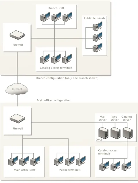
Located in a large city, the library system is anchored by a main downtown location serving most of the population, with a dozen branches spread throughout the city. Each branch is wired to the Internet but none are linked with each other by dedicated connections.
Current topology and security concerns
Each office connects to the Internet with no standard access policy or centralized management and monitoring.
The library system does not log Internet traffic and does not have the means to do so on a system-wide basis. In the event of legal action involving network activity, the library system will need this information to protect itself.
The branches currently communicate with the main office through the Internet with no encryption. This is of particular concern because all staff members access the central email server in the main office. Email sent to or from branch office staff could be intercepted.
Both the main and branch offices are protected from the Internet by firewalls. This protection is limited to defending against unauthorized intrusion. No virus, worm, phishing, or spyware defences protect the network, resulting in computer downtime when an infection strikes.
Like the branches, the main office is protected by a single firewall device
connected the Internet. Should this device fail, connectivity will be lost. The library system’s web page and catalog are mission critical applications and access would be better protected by redundant hardware.
The internal network at each location has staff computers and public access terminals connected together. Concerns have been raised over possible vulnerabilities involving staff computers and public terminals sharing the same network.
Budgetary constraints limit the number of public access terminals the library can provide. With the popularity of WiFi enabled laptops, the addition of a wireless access point is an economical way to allow library patrons to access the Internet using their own equipment.
Efficient use of the library’s limited public access terminals and bandwidth can be compromised by the installation and use of instant messaging and peer to peer file sharing applications.
Use of library resources to browse inappropriate content is a problem. These activities are prohibited by library policies, but there is no technical means of enforcement, leaving it to the staff to monitor usage as best they can.
Library requirements Example library network
Figure 1: The library system’s current network topology
Library requirements
• VPN to secure all traffic between main and branch offices. • Public wireless Internet access for mobile clients.
• Strict separation of public access terminals from staff computers.
• An automatically maintained and updated system for stopping viruses and intrusions at the firewall.
• Instant messaging is blocked for public Internet terminals and public wireless access, but not for staff. Peer-to-peer downloads are blocked network-wide. • All Internet traffic from branch offices travels securely to the main office and
then out onto the Internet. Inbound traffic follows the reverse route. This allows a single point at which all protection profiles and policies may be applied for simplified and consistent management.
Main office staff Public terminals
Catalog access terminals DMZ Catalog access terminals
Public terminals Branch staff
Internet
Branch configuration (only one branch shown)
Main office configuration
Firewall Mail server Web server Catalog server Firewall
Example library network Library requirements
• The ability to block specific web sites and whole categories of sites from those using the public terminals and public wireless access if deemed necessary. Users granted special permission should be allowed to bypass the restrictions. • Public access traffic originates from a different address than staff and server
traffic.
• DMZ for web and email server hosting in main office.
• The library catalog is available on the library’s web page allowing public access from anywhere.
The library’s decision The Fortinet solution
The Fortinet solution
The library’s decision
Every model of the FortiGate Dynamic Threat Prevention System offers real time network protection to detect and eliminate the most damaging, content-based threats from email and Web traffic such as viruses, worms, intrusions,
inappropriate Web content and more in real time — without degrading network performance.
The library decided to standardize on the FortiGate-800 and the FortiWiFi-60A: • Two FortiGate-800 units for main office. These enterprise-level devices have
the processing power and speed to handle the amount of traffic expected of a large busy library system with public catalog searches, normal staff use, and on-site research using the Internet as a resource. The two units are
interconnected in HA (high availability) mode to ensure uninterrupted service in the case of failure. A FortiWiFi-60A is also used to provide wireless access for patrons in main office.
• A FortiWiFi-60A for each branch office. In addition to being able to handle the amount of traffic expected of a branch office, the FortiWiFi-60A provides wireless access for library patrons.
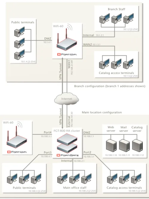
Proposed topology
Figure 2 shows the proposed network topology utilizing the FortiGate units. Only one branch office is shown in the diagram although more than a dozen are configured in the same way, including the VPN connection to the main office. The VPN connections between the branch offices and the main office are a critical feature securing communication between locations.
The two FortiGate-800 units in HA mode serve as the only point through which traffic flows between the Internet and the library’s network, including the branch offices. VPN connections between the main and branch offices provide the means to securely send data in either direction.
Branch Internet browsing traffic is routed to the main office through the VPN by the branch’s FortiWiFi-60A. After reaching the FortiGate-800 at the main office, the traffic continues out to the Internet. Inbound traffic follows the same path back to the branch office.
With two FortiGate-800 units in HA mode serving as a single point of contact to the Internet, only two FortiGuard subscriptions are required to protect the entire network. Otherwise each branch would also need separate FortiGuard
subscription. The FortiGuard web filtering service can also be configured on the FortiGate-800 units, ensuring consistent web filtering policies for all locations. No provision is made for direct communication between branches.
The Fortinet solution Proposed topology
Figure 2: Proposed library system network topology
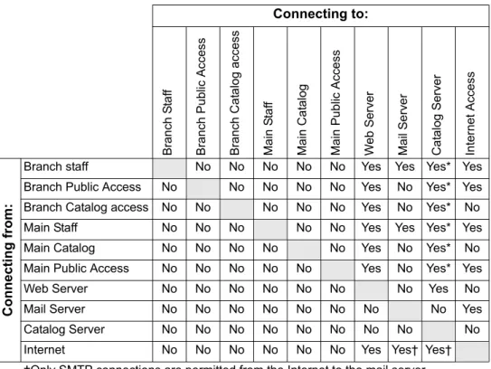
Table 1 on page 18 details the allowed connectivity between different parts of the network.
10.100.1.3 10.100.1.3 10.100.1.3
Public terminals Main office staff
FGT-800 HA cluster
Catalog access terminals DMZ Internet VPN T unnel VPN T unnel
Branch configuration (branch 1 addresses shown)
Main location configuration
WiFi-60 WiFi-60 Port2 Internal Port3 Ext er nal W AN1 Internal DMZ WAN2 1 92. 1 6 8. 14 7.30 10.100.4.1 10.100.1.1 10.100.3.1 10.100.2.1 1 92. 1 6 8.23.89 10.1.3.1 10.1.4.1 10.1.2.1 10.100.1.10 10.100.1.11 10.100.1.12 10.100.2.[2-254] 10.100.3.[2-254] 10.100.4.[2-254]
Catalog access terminals 10.1.3.[2-254] Branch Staff 10.1.2.[2-254] Web server Mail server Catalog server Port4 10.100.5.1 Public terminals 10.1.4.[2-254]
Proposed topology The Fortinet solution
Table 1: Access permission between various parts of the network
Connecting to: Bran ch S taf f Branch Public Access Branch Cat a log ac cess Main S taf f Mai n Cat alog Main P u blic Access We b S er ve r Mail S e rv er Ca ta log Server Internet Access Conn ect ing fro m :
Branch staff No No No No No Yes Yes Yes* Yes
Branch Public Access No No No No No Yes No Yes* Yes
Branch Catalog access No No No No No Yes No Yes* No
Main Staff No No No No No Yes Yes Yes* Yes
Main Catalog No No No No No Yes No Yes* No
Main Public Access No No No No No Yes No Yes* Yes
Web Server No No No No No No No Yes No
Mail Server No No No No No No No No Yes
Catalog Server No No No No No No No No No
Internet No No No No No No Yes Yes† Yes†
†Only SMTP connections are permitted from the Internet to the mail server.
* An indirect connection. Access to the catalog is through the library web page. Direct connections to the catalog server are not permitted.
The Fortinet solution Features used in this example
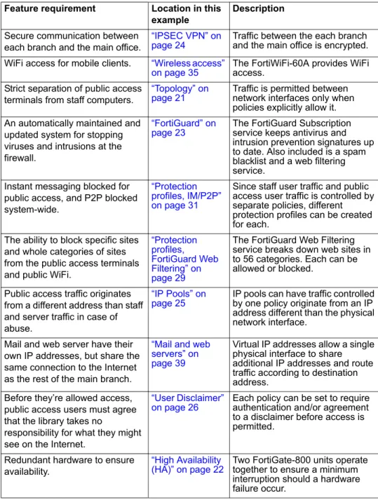
Features used in this example
Table 2: Features used to fulfil requirements Feature requirement Location in this
example
Description
Secure communication between each branch and the main office.
“IPSEC VPN” on
page 24 Traffic between the each branch and the main office is encrypted.
WiFi access for mobile clients. “Wireless access”
on page 35 The FortiWiFi-60A provides WiFi access. Strict separation of public access
terminals from staff computers.
“Topology” on
page 21 Traffic is permitted between network interfaces only when policies explicitly allow it. An automatically maintained and
updated system for stopping viruses and intrusions at the firewall.
“FortiGuard” on
page 23 The FortiGuard Subscription service keeps antivirus and intrusion prevention signatures up to date. Also included is a spam blacklist and a web filtering service.
Instant messaging blocked for public access, and P2P blocked system-wide.
“Protection profiles, IM/P2P” on page 31
Since staff user traffic and public access user traffic is controlled by separate policies, different protection profiles can be created for each.
The ability to block specific sites and whole categories of sites from the public access terminals and public WiFi.
“Protection profiles, FortiGuard Web Filtering” on page 29
The FortiGuard Web Filtering service breaks down web sites in to 56 categories. Each can be allowed or blocked.
Public access traffic originates from a different address than staff and server traffic in case of abuse.
“IP Pools” on
page 25 IP pools can have traffic controlled by one policy originate from an IP address different than the physical network interface.
Mail and web server have their own IP addresses, but share the same connection to the Internet as the rest of the main branch.
“Mail and web servers” on page 39
Virtual IP addresses allow a single physical interface to share additional IP addresses and route traffic according to destination address.
Before they’re allowed access, public access users must agree that the library takes no
responsibility for what they might see on the Internet.
“User Disclaimer”
on page 26 Each policy can be set to require authentication and/or agreement to a disclaimer before access is permitted.
Redundant hardware to ensure availability.
“High Availability
(HA)” on page 22 Two FortiGate-800 units operate together to ensure a minimum interruption should a hardware failure occur.
Network addressing The Fortinet solution
Network addressing
The IP addresses used on the library’s internal network follow a 10.x.y.z structure with a 255.255.255.0 subnet mask, where:
• x is the branch number. The main office uses 100 while the branches are assigned numbers starting with 1
• y indicates the purpose of the attached devices in this range: • 1 - servers and other infrastructure
• 2 - staff computers • 3 - catalog terminals • 4 - public access terminals • 5 - public WiFi access
• z is a range of individual machines
For example, 10.3.2.15 and 10.3.2.27 are two staff members' computers in the third library branch.
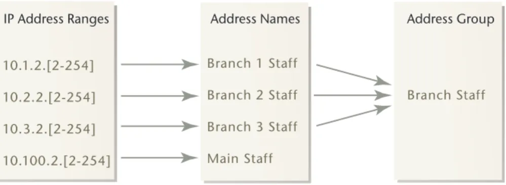
Assigning IP addresses by location and purpose allows network administrators to define addresses and address ranges to descriptive names on the FortiGate unit. These address names then can also be incorporated into address groups for easy policy maintenance.
For example, the address range 10.1.2.[2-254] is assigned the name
Branch_1_Staff on the FortiGate-800 unit. Anytime a policy is required for traffic from the staff in branch 1, this address name can be selected. Further, once an address name is specified for the staff of each branch, all of those names can be combined into an address group named Branch_Staff so all the branch staff can be referenced as a single entity.
Figure 3: IP address ranges are assigned names, and the names combined into address groups.
The address names defined on the FortiGate-800 for Branch 1 traffic are Branch_1_Staff (10.1.2.2-10.1.2.254), Branch_1_Catalog (10.1.3.2-10.1.3.254), Branch_1_Public (10.1.4.2-10.1.4.254), and Branch_1_WiFi
(10.1.5.2-10.1.5.254). Four address groups will be created incorporating each type of address name from all the branches: Branch_Staff, Branch_Catalog, Branch_Public, and Branch_WiFi.
At the main office, additional address names are configured for the web server (Web_Server) and for the web and email servers combined (Servers).
Address names are configured in Firewall > Address > Address. Address groups are configured in Firewall > Address > Group.
10.1.2.[2-254] 10.2.2.[2-254] 10.3.2.[2-254] 10.100.2.[2-254] Branch 1 Staff Branch 2 Staff Branch 3 Staff Main Staff Branch Staff
Configuring the main office Topology
Configuring the main office
The FortiGate-800 cluster forms the hub of virtually all network communication, whether within the main office, from the branch offices to the main branch, or from anywhere in the library network to the Internet. This way, all virus scanning, spam and web filtering, as well as access restrictions can be centralized and maintained in this one place.
Topology
The main office network layout is designed to keep the various parts of the network separate. Computers on different segments of the network cannot contact each other unless a FortiGate policy is created to allow the connection. Public terminals can access the library’s web server for example, but they cannot access any machines belonging to staff members. See Table 1 on page 18 for details on permitted access between different parts of the library network.
Staff computers, email and web servers, public access terminals, and WiFi connected systems are all protected by the FortiGuard service on the
FortiGate-800 cluster. Push updates ensure the FortiGate unit is up to date and prepared to block viruses, worms, spyware, and attacks.
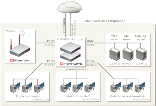
Figure 4: Main branch network topology
10.100.1.3 10.100.1.3 10.100.1.3
Public terminals Main office staff
FGT-800 HA cluster
Catalog access terminals DMZ
Internet
VPN T
unnel Main location configuration
WiFi-60 Port2 Internal Port3 Ext er nal 1 92. 1 68. 14 7.30 10.100.4.1 10.100.1.1 10.100.3.1 10.100.2.1 10.100.1.10 10.100.1.11 10.100.1.12 10.100.2.[2-254] 10.100.3.[2-254] 10.100.4.[2-254] Web server Mail server Catalog server Port4 10.100.5.1
High Availability (HA) Configuring the main office
High Availability (HA)
The two FortiGate-800 units will be connected in a high-availability (HA) cluster in active-active mode. This is a redundant configuration ensuring network traffic will be virtually uninterrupted should one unit fail. If only a single unit were present and experienced problems, the main branch would be cut-off from the Internet and the branch offices. Because the branches route their traffic through the main office, they’d also be isolated. Active-active mode has the advantage of using the processing power of the subordinate unit to increase the efficiency of antivirus scanning. The two FortiGate-800 units fulfil a mission-critical role.
Configuring HA
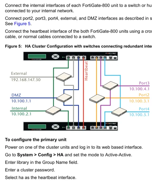
Connect the cluster units to each other and to your network. You must connect all matching interfaces in the cluster to the same hub or switch. Then you must connect these interfaces to their networks using the same hub or switch. To connect the cluster units
1 Connect the internal interfaces of each FortiGate-800 unit to a switch or hub connected to your internal network.
2 Connect port2, port3, port4, external, and DMZ interfaces as described in step 1. See Figure 5.
3 Connect the heartbeat interface of the both FortiGate-800 units using a crossover cable, or normal cables connected to a switch.
Figure 5: HA Cluster Configuration with switches connecting redundant interfaces
To configure the primary unit
1 Power on one of the cluster units and log in to its web based interface. 2 Go to System > Config > HA and set the mode to Active-Active. 3 Enter library in the Group Name field.
4 Enter a cluster password.
5 Select ha as the heartbeat interface. 6 Select OK. Esc Enter CONSOLE I N T E R N A LE X T E R N A L D M Z HA 1 2 3 4 USB 8 P W R Esc Enter CONSOLE I N T E R N A LE X T E R N A L D M Z HA 1 2 3 4 USB 8 P W R External Internal Hear tbeat DMZ Port2 Port3 192.168.147.30 10.100.2.1 10.100.4.1 10.100.3.1 10.100.1.1 Port4 10.100.5.1
Configuring the main office FortiGuard
7 Go to System > Network > Interface and set the interface IP addresses as indicated in Figure 5 on page 22
To configure the subordinate unit
1 Power on the subordinate cluster unit and log in to its web based interface. 2 Go to System > Config > HA and set the mode to Active-Active.
3 Change the device priority from the default 128 to 64. The FortiGate unit with the highest device priority in a cluster becomes the primary unit.
4 Enter library in the group name field. 5 Enter the cluster password.
6 Select ha as the heartbeat interface. 7 Select OK.
The two cluster units will then connect begin communication to determine which will become the primary. The primary will then transfer its own configuration data to the subordinate. In the few minutes required for this process, traffic will be interrupted. Once completed, the two clustered units will appear as a single FortiGate unit to the network.
You can now configure the cluster as if it were a single FortiGate unit.
HA is configured in System > Config > HA. For more information about HA, see the FortiGate HA Overview on the Fortinet Technical Documentation web page.
FortiGuard
Four FortiGate features take advantage of the FortiGuard Service. They are Antivirus, Intrusion Prevention, Web Filtering, and Antispam
Antivirus and intrusion prevention (IPS) signatures are updated automatically to detect new attacks and viruses with FortiGuard updates. Virus scanning and IPS are configured in protection profiles.
FortiGuard Web filtering is enabled and configured in each protection profile. When a web page is requested, the URL is sent to the FortiGuard service and the category it belongs to is returned. The FortiGate unit checks the FortiGuard Web Filtering settings and allows or blocks the web page. The FortiGuard Web Filtering is configured in protection profiles.
FortiGuard Antispam is also enabled or disabled in each protection profile. The FortiGuard service is consulted on whether each message in question is spam, and the FortiGate acts accordingly. There are a number of ways to check a message, and each method can be enabled or disabled in the protection profile. The Antispam is configured in protection profiles.
Note: All the FortiGate units in a cluster must have unique host names. Default host names are the device serial numbers so unique names are automatic unless changed. If any Forti-Gate device host names have been changed, confirm that there is no duplication in those to be clustered.
IPSEC VPN Configuring the main office
IPSEC VPN
The main office serves as a hub for the VPN connections from the branch offices. To make the generation and maintenance of the required policies simpler, interface-mode VPNs will be used. Interface-mode VPNs are configured largely the same as tunnel-mode VPNs, but the way they’re use differs significantly. Interface-mode VPNs appear as network interfaces, like the DMZ, port2, and external network interfaces.
Network topology is easier to visualize because you no longer have a single interface sending and receiving both encrypted VPN traffic and unencrypted regular traffic. Instead, the physical interface handles the regular traffic, and the VPN interface handles the encrypted traffic. Further, policies no longer need to specify whether traffic is IPsec encrypted. If traffic is directed to a VPN interface, the FortiGate unit knows it is to be encrypted.
Interface-mode VPNs are used in this configuration because they will require far fewer policies. Policies for tunnel-mode VPNs require selection of a tunnel in the policy. Many tunnels can connect to a single physical interface, so the policy needs to know what traffic it is responsible for.
Since interface-mode VPNs are used as any other network interface, they can be collected into a zone and treated as a single entity. Addressing names and groups differentiate what type of user is generating the traffic, so what tunnel it comes out of isn’t important in the library’s configuration. All branch offices are treated the same.
For example, using tunnel-mode VPNs, 12 branches would require twelve policies to allow employees to connect directly to the email and web servers. The branch 1 policy would allow the IP range defined for staff coming from the branch 1 tunnel access to the DMZ. A second policy would allow the IP range defined for staff coming from the branch 2 tunnel access to the DMZ, and so on. Since the tunnel must be specified, there must be one policy for each tunnel, and this is just for branch staff to DMZ traffic. In the library’s network configuration, there are nine traffic type/destination combinations using the VPN. This would require 108 policies for 12 branches.
To simplify things we instead give names to the address ranges based on use and location. IP address range 10.1.2.[2-255] is named Branch 1 Staff and
10.2.2.[2-255] is named Branch 2 Staff. The same procedure is followed for the remainder of the branches and all the resulting branch staff names are put into an address group called Branch Staff. All branch staff computers can be referenced with a single name. Similarly, after all the branch VPNs are created and named Branch 1, Branch 2, etc., they can be combined into a single zone named Branches.
From here, it’s a simple matter to configure a single policy to handle staff traffic from all branches to the email and web servers located on the main office DMZ rather than a policy for each branch office. Should any branch require special treatment, its VPN interface can be removed from the zone and separate policies tailored to it.
Configuring the main office IP Pools
Configuring IPSEC VPNs
The VPNs secure data exchanged between each branch and the main office. To create the main office VPN connection to branch 1
1 Go to VPN > IPSEC > Auto Key (IKE).
2 Select the Create Phase 1 button and enter Branch 1 in the Name field. 3 Select Static IP Address for Remote Gateway.
4 Enter 192.168.23.89 in the IP Address field. 5 Select External for the Local Interface. 6 Select Main (ID Protection) for the Mode.
7 Select Preshared Key as the Authentication Method. 8 Enter the preshared key in the Preshared Key field. 9 Select advanced and select Enable IPsec Interface Mode.
To configure the Phase 2 portion of the VPN connection to Branch 1 1 Go to VPN > IPSEC > Auto Key (IKE).
2 Select the Create Phase 2 button. 3 Enter Main to Branch 1 in the name field. 4 Select Branch 1 from the Phase 1 drop down.
The advanced options can be left to their default values.
The configuration steps to create the VPN tunnel have to be repeated for each branch office to be connected in this way. Additional branches use the same Phase 1 settings except for Name, IP Address, and Preshared Key.
IP Pools
IP Pools allow the traffic leaving an interface to use an IP address different than the one assigned to the interface itself. One use of IP pools is if the users receive a type of traffic that cannot be mapped to different ports.Without IP pools, only one user at a time could send and receive these traffic types.
In the library’s case, a single IP address will be put into an IP pool named Public_Access_Address. All of the policies that allow traffic from the public access terminals (including the WiFi access point) will be configured to use this IP pool. The result is that any traffic from the public access terminals will appear to be coming from the IP pool address rather than the external interface’s IP address. This is true even though the public access traffic will flow out of the external interface.
Note: The preshared key is a string of alphanumeric characters and should be unique for each branch. The preshared key entered at each end of the VPN connection must be iden-tical.
User Disclaimer Configuring the main office
The purpose is to separate the public access users from the library staff from the point of view of the Internet at large. Should a library patron abuse the Internet connection by sending spam or attempting to unlawfully access to a system out on the Internet, any action taken against the source IP will not inconvenience staff. The library can continue to function normally while the problem is dealt with.
Configuring IP pools
To add a new IP pool for public access users.
1 Go to Firewall > Virtual IP > IP Pool and select Create New. 2 Enter Public_Access_Address in the name field.
3 From the interface drop down, select external.
4 In the IP Range/Subnet field, enter 192.168.230.64. This address was obtained from the library’s Internet service provider.
5 Select OK.
The IP pool named Public_Access_Address will now be available for selection in any policy where the destination interface is set to external, NAT is enabled, and Dynamic IP Pool is enabled.
User Disclaimer
When using the public terminals or wireless access, the first time a web page external to the library’s network is requested, a disclaimer will pop up. This is configured in policies controlling access to the Internet. The user must agree to the stated conditions before they can continue.
Configuring the user disclaimer
The disclaimer message is set in System > Config > Replacement Messages > Authentication > Disclaimer page. The default message is changed to
reference the library instead of the generic ‘network access provider’ as shown here:
You are about to access Internet content that is not under the control of the library. The library is therefore not responsible for any of these sites, their content, or their privacy policies. The library and its staff do not endorse or make any
representations about these sites, or any information, software, or other products or materials found there, or any results that may be obtained from using them. If you decide to access any Internet content, you do this entirely at your own risk and you are responsible for ensuring that any accessed material does not infringe the laws governing, but not exhaustively covering, copyright, trademarks,
pornography, or any other material which is slanderous, defamatory or might cause offence in any other way.
Do you agree to the above terms?
Note: Although IP pools are usually created with a range of addresses, an IP pool with a single address is valid.
Configuring the main office Protection Profiles
If the user decides not to agree to the disclaimer, a second message appears and they are not allowed to communicate with any systems out on the Internet. This second disclaimer message is set in System > Config > Replacement
Messages > Authentication > Declined disclaimer page. The default text of this declined disclaimer is acceptable:
Sorry, network access cannot be granted unless you agree to the disclaimer. The enabling this feature will be detailed in the policy configuration steps.
Protection Profiles
Policies control whether traffic flowing through a FortiGate unit from a given source is allows to travel to a given destination. Protection profiles are selected in each policy and define how the traffic is examined and what action may be taken based on the results of the examination. But before they can be selected in a policy, protection profiles have to be defined.
A brief overview is given for a typical protection profile, and the information required for all protection profiles, in this example, follows in table form.
For complete policy construction steps, see the FortiGate Administration Guide. To create a protection profile
1 Go to Firewall > Protection Profile and select Create New. 2 Enter a name and description for the profile.
3 Configure the following options: • Anti-Virus
• Web filtering
• FortiGuard web filtering • Spam filtering • IPS • Content archive • IM/P2P • VoIP • Logging 4 Select Apply.
The following tables provide all the settings of all four protection profiles used in the library network example. Each table focuses on one section of the protection profile settings:
• Protection profile name and comment, see Table 3 on page 28 • Antivirus settings, see Table 4 on page 28
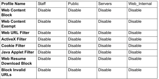
• Web-Filtering, see Table 5 on page 29
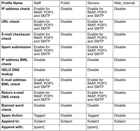
• FortiGuard Web Filtering, see Table 6 on page 29 • Spam Filtering, see Table 7 on page 30
Protection Profiles Configuring the main office
• VoIP, see Table 11 on page 31 • Logging, see Table 12 on page 31
The comment field is optional, but recommended. With many profiles, the comment can be invaluable in quickly identifying profiles.
Note: The settings in the tables listed below are for the library example only. For complete
protection profile information see the FortiGate Administration Guide.
In this example, if a setting is to be left in the default setting, it is not expanded in the tables below.
Table 3: Protection profiles, Name and Comments
Profile Name Staff Public Servers Web_Internal
Comment (optional)
Use with all policies for traffic from staff computers.
Use with all policies for traffic from the public access or WiFi.
Use for policies allowing the public access to the library web server from the Internet, or email server communication.
Use for policies allowing access to the library web server from catalog terminals.
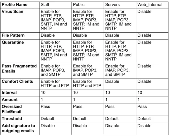
Table 4: Protection profiles, Antivirus settings
Profile Name Staff Public Servers Web_Internal
Virus Scan Enable for HTTP, FTP, IMAP, POP3, SMTP, IM and NNTP Enable for HTTP, FTP, IMAP, POP3, SMTP, IM and NNTP Enable for HTTP, FTP, IMAP, POP3, SMTP, IM and NNTP Disable
File Pattern Disable Disable Disable Disable
Quarantine Enable for HTTP, FTP, IMAP, POP3, SMTP, IM and NNTP Enable for HTTP, FTP, IMAP, POP3, SMTP, IM and NNTP Enable for HTTP, FTP, IMAP, POP3, SMTP, IM and NNTP Disable Pass Fragmented Emails Enable for IMAP, POP3, and SMTP Enable for IMAP, POP3, and SMTP Enable for IMAP, POP3, and SMTP Disable
Comfort Clients Enable for
HTTP and FTP Enable for HTTP and FTP Disable Disable
Interval 10 10 10 10
Amount 1 1 1 1
Oversized File/Email
Pass Pass Pass Pass
Threshold Default Default Default Default
Add signature to outgoing emails
Disable Disable Disable Disable
Note: The FortiGate unit must have either an internal hard drive or a configured FortiAnalyzer unit for the Quarantine option to appear.
Configuring the main office Protection Profiles
Web filtering is disabled but can be enabled should a threat or abuse be discovered at a later time.
*The Public protection profile has FortiGuard web filtering enabled and set to block advertising, malware, and spyware categories. Additional categories can be
Table 5: Protection profiles, Web-Filtering
Profile Name Staff Public Servers Web_Internal
Web Content Block
Disable Disable Disable Disable
Web Content Exempt
Disable Disable Disable Disable
Web URL Filter Disable Disable Disable Disable
ActiveX Filter Disable Disable Disable Disable
Cookie Filter Disable Disable Disable Disable
Java Applet Filter Disable Disable Disable Disable
Web Resume Download Block
Disable Disable Disable Disable
Block Invalid URLs
Disable Disable Disable Disable
Table 6: Protection profiles, FortiGuard Web Filtering
Profile Name Staff Public Servers Web_Internal
Enable
FortiGuard Web Filtering
Disable Enable* Disable Disable
Enable
FortiGuard Web Filtering Override
Disable Disable Disable Disable
Provide details for blocked HTTP 4xx and 5xx errors
Disable Enable Disable Disable
Rate images by URL (blocked images will be replaced with blanks)
Disable Enable Disable Disable
Allow websites when a rating error occurs
Disable Disable Disable Disable
Strict Blocking Enable Enable Enable Enable
Rate URLs by domain and IP address
Protection Profiles Configuring the main office
Email is not scanned for spam using the Public protection profile. Users of the public access terminals will use their own webmail accounts if checking mail, and WiFi connected users will have their own spam solutions, if desired.
Individual IPS signatures and anomalies have a preset severity, but these can be changed if required. IPS signatures are configured in Intrusion Protection > Signature > Predefined, the protocol decoders in Intrusion Protection > Signature > Protocol Decoder, and the anomalies in Intrusion Protection > Anomaly > Anomaly.
Table 7: Protection profiles, Spam Filtering
Profile Name Staff Public Servers Web_Internal
IP address check Enable for IMAP, POP3 and SMTP
Disable Enable for
IMAP, POP3 and SMTP
Disable
URL check Enable for IMAP, POP3 and SMTP
Disable Enable for
IMAP, POP3 and SMTP Disable E-mail checksum check Enable for IMAP, POP3 and SMTP
Disable Enable for
IMAP, POP3 and SMTP
Disable
Spam submission Enable for IMAP, POP3 and SMTP
Disable Enable for
IMAP, POP3 and SMTP
Disable
IP address BWL check
Disable Disable Disable Disable
HELO DNS lookup
Disable Disable Disable Disable
E-mail address BWL check
Enable for IMAP, POP3 and SMTP
Disable Enable for
IMAP, POP3 and SMTP Disable Return e-mail DNS check Enable for IMAP, POP3 and SMTP
Disable Enable for
IMAP, POP3 and SMTP
Disable
Banned word check
Disable Disable Disable Disable
Spam Action Tagged Disable Tagged Disable
Append to: Subject Subject Subject Subject
Append with: [spam] [spam]
Table 8: Protection profiles, IPS
Profile Name Staff Public Servers Web_Internal
IPS Signature Enable Critical, High, Medium, Low, and Information Enable Critical, High, Medium, Low, and Information Enable Critical, High, Medium, Low, and Information Disable
IPS Anomaly Enable Critical, High, Medium, Low, and Information Enable Critical, High, Medium, Low, and Information Enable Critical, High, Medium, Low, and Information Disable
Configuring the main office Protection Profiles
The default content archive settings are ideal for the current library configuration. Should detailed logging be required, a FortiAnalyzer can be added to the network and these settings adjusted.
Staff employees are permitted to use instant messaging while public access users are not. All users have peer to peer clients blocked.
The library system does not currently use VoIP phones.
The logging of oversized files and email messages is disabled because oversized messages and email messages are not blocked. If blocking files and messages is ever considered, logging can be enabled to get an accurate idea of what the effects will be.
Table 9: Protection profiles, Content Archive
Profile Name Staff Public Servers Web_Internal
All settings Default values Default values Default values Default values
Table 10: Protection profiles, IM/P2P
Profile Name Staff Public Servers Web_Internal
Block Login Disable for all
IM protocols Enable for all IM protocols Disable Disable
Block File Transfers
Disable for all
IM protocols Disable Disable Disable
Block Audio Disable for all
IM protocols Disable Disable Disable
Inspect Non-standard Port
Enable for all
IM protocols Enable for all IM protocols Disable Disable
Action Block for all
P2P protocols Block for all P2P protocols Block for all P2P protocols Block for all P2P protocols
Limit (KBytes/s) n/a n/a n/a n/a
Table 11: Protection profiles, VoIP
Profile Name Staff Public Servers Web_Internal
All settings Default values Default values Default values Default values
Table 12: Protection profiles, Logging
Profile Name Staff Public Servers Web_Internal
All settings Enable all options except Oversized Files / E-mails and VoIP Enable all options except Oversized Files / E-mails and VoIP Enable all options except Oversized Files / E-mails and VoIP Enable all options except Oversized Files / E-mails and VoIP
Staff access Configuring the main office
Staff access
Staff members can access the Internet as well as directly connect to the library web and email servers.
Since the network uses private addresses and has no internal DNS server, connections to the web and email servers must be specified by IP address. The private network address will keep all communication between the server and email client on the local network and secure against interception on the Internet. If a staff member attempts to open the library web page or connect to the email server using either server’s virtual IP or fully qualified domain name, their request goes out over the Internet, and returns through the FortiGate unit. This method will make their transmission vulnerable to interception.
The web browsers on staff computers will be configured with the library web page as the default start page. Staff members’ email software should be configured to use the email server’s private network IP address rather than the virtual IP or fully qualified domain name. These two steps will prevent staff from having to
remember the servers’ IP addresses.
Creating firewall policy for staff members
The first firewall policy for main office staff members allows full access to the Internet at all times. A second policy will allow direct access to the DMZ for staff members. A second pair of policies are required to allow branch staff members the same access.
The staff firewall policies will all use a protection profile configured specifically for staff access. Enabled features include virus scanning, spam filtering, IPS, and blocking of all P2P traffic. FortiGuard web filtering is also used to block advertising, malware, and spyware sites.
A few users may need special web and catalog server access to update information on those servers, depending on how they’re configured. Special access can be allowed based on IP address or user.
A brief overview procedure is given for a typical policy, and the information required for all staff policies follows in table form. For more detailed information see the FortiGate Administration Guide.
Step-by-step policy creation example
1 To create a policy to allow main office staff to connect to the Internet, go to Firewall > Policy and select Create New.
2 Fill in the following fields: • Source interface/Zone • Source address • Destination interface/Zone • Schedule • Service • Action • NAT • Protection Profile • Log allowed traffic
Configuring the main office Catalog terminals
• Traffic shaping
• User authentication disclaimer • Comments (optional)
3 Select OK.
The settings required for all staff policies are provided in Table 13.
Catalog terminals
Dedicated computers are provided for the public to search the library catalog. The only application available on the catalog terminals is a web browser, and the only site the catalog terminal web browser can access is the library web page, which includes access to the catalog. The browser is configured to use the library web
Table 13: Library staff policies Main office staff connect to the Internet Main office staff connect to library servers Branch office staff connect to the Internet Branch office staff connect to library servers Source Interface/Zone
Internal Internal Branches Branches
Source Address
All All Branch_Staff Branch_Staff
Destination Interface/Zone
External DMZ External DMZ
Destination Address
All Servers All Servers
Schedule Always Always Always Always
Service All All All All
Action Accept Accept Accept Accept
NAT Enable Enable Enable Enable
Protection Profile
Enable and
select Staff Enable and select Staff Enable and select Staff Enable and select Staff
Log Allowed Traffic
Enable Enable Enable Enable
Authentication Disable Disable Disable Disable
Traffic Shaping Disable Disable Disable Disable
User
Authentication Disclaimer
Disable Disable Disable Disable
Comment (optional)
Main office: staff computers connecting to the Internet.
Main office: staff computers connecting to the library servers. Branch offices: staff computers connecting to the Internet. Branch offices: staff computers connecting to the library servers.
Public access terminals Configuring the main office
Creating firewall policies for catalog terminals
The policy used for the catalog access terminals only allows communication with the DMZ. Create two new policies, one for main office access and another to allow access from the branch offices.
The settings required for all catalog terminal policies in this example are provided in Table 14 on page 34.
For complete policy construction steps, see the FortiGate Administration Guide.
Public access terminals
Terminals are provided for library patrons to access the Internet. Protection profile settings block all instant messaging and peer to peer connections. In addition, library staff can block individual sites and entire site categories as deemed necessary. Site categories are blocked using FortiGuard web filtering configured in the protection profile.
Creating firewall policies for public access terminals
Library users can access the Internet from the public terminals. The public terminal machines have the library’s web page as the web browser’s default start page. The address is the web server’s private network IP so the traffic between the terminal and the web server remains on the library’s network.
Table 14: Catalog terminal policies
Main office catalog terminals connect to web server
Branch office catalog terminals connect to web server
Source Interface/Zone port2 Branches
Source Address All Branch_Catalog
Destination Interface/Zone DMZ DMZ
Destination Address Web_Server Web_Server
Schedule Always Always
Service HTTP HTTP
Action Accept Accept
NAT Enable Enable
Protection Profile Disable Disable
Log Allowed Traffic Enable Enable
Authentication Disable Disable
Traffic Shaping Disable Disable
User Authentication Disclaimer
Disable Disable
Comment (optional) Main office: catalog terminals
connecting to the web server. Branch offices: catalog terminals connecting to the
Configuring the main office Wireless access
The settings required for all public access terminal policies in this example are provided in Table 15 on page 35.
For complete policy construction steps, see the FortiGate Administration Guide.
Wireless access
Wireless access allow library visitors to browse the Internet from their own
Table 15: Public access terminal policies Main office Public access users connect to Internet Main office public access users connect to web server Branch offices public access users connect to Internet Branch offices public access users connect to web server Source Interface/Zone
Port3 Port3 Branches Branches
Source Address
Main_Public Main_Public Branch_Public Branch_Public
Destination Interface/Zone
External DMZ External DMZ
Destination Address
All Web_Server All Web_Server
Schedule Always Always Always Always
Service All HTTP All HTTP
Action Accept Accept Accept Accept
NAT Enable NAT,
enable Dynamic IP Pool and select
Public_Access_ Address
Enable NAT. Enable NAT,
enable Dynamic IP Pool and select Public_Access_ Address Enable NAT. Protection Profile Enable and
select Public Enable and select
Web_Internal
Enable and
select Public Enable and select
Web_Internal
Log Allowed Traffic
Enable Enable Enable Enable
Authentication Disable Disable Disable Disable
Traffic Shaping Disable Disable Disable Disable
User Authentication Disclaimer Enable User Authentication Disclaimer and leave Redirect URL field blank.
Disable Enable User
Authentication Disclaimer and leave Redirect URL field blank.
Disable Comments (optional) Main office: public access terminals connecting to the Internet. Main office: public access terminals connecting to the library web server. Branch offices: public access terminals connecting to the Internet. Branch offices: public access terminals connecting to the library web server.
Wireless access Configuring the main office
Security considerations
The wireless interface of the FortiWiFi-60A will have its DHCP server assign IP addresses to users wanting to connect to the Internet. The FortiWiFi-60A will also have its SSID broadcast and set to ‘library’ or something similarly identifiable. Stricter security would be of limited value because anyone could request and receive access. Also, library staff would spend significant time serving as technical support to patrons not entirely familiar with their own equipment. Instead, the firewall policy applied to wireless access will limit Internet connectivity to the main office’s business hours.This decision will be reviewed periodically, especially if public access is abused.
Wireless security is configured in System > Wireless > Settings. The number of concurrent wireless users can be adjusted by reducing or
expanding the range of addresses the DHCP server on the WiFi port has available to assign. Using this means of limiting users is only partially effective because some users may set a static address in the same subnet and gain access. To prevent this, configure the IP range specified in the address name used in the policy to have the same range the DHCP server assigns. Users can still set a static IP, but the policy will not allow any access.
The wireless DHCP server is configured in System > Network > Interface. Select the edit icon for the wlan interface.
Creating schedules for wireless access
Library users can access the Internet from the WiFi connection. The policies used for WiFi incorporates a schedule to limit Internet access to only when the library is open to the public.
The protection profile used for library users enables virus scanning, IPS, and blocking of all P2P traffic and IM logins. Spam filtering is not enabled. FortiGuard web filtering is used to block malware, and spyware sites. Additional categories can be blocked if required by library policy.
The library hours are:
Because of the varying library hours through the week, three separate schedules are required, as shown in Figure 6.
Figure 6: Policy schedules
To create Monday to Thursday business hours schedule 1 Go to Firewall > Schedule > Recurring and select Create New. 2 Enter Mon-Thurs for the schedule name.
Mon-Thurs 10am - 9pm
Fri-Sat 10am - 6pm
Configuring the main office Wireless access
3 Select the check boxes for Monday, Tuesday, Wednesday, and Thursday. 4 Select 10 for the start hour and 00 for the start minute.
5 Select 21 for the end hour and 00 for the end minute. 6 Select OK.
To create Friday and Saturday business hours schedule 1 Go to Firewall > Schedule > Recurring and select Create New. 2 Enter Fri-Sat for the schedule name.
3 Select the check boxes for Friday, and Saturday. 4 Select 10 for the start hour and 00 for the start minute. 5 Select 18 for the end hour and 00 for the end minute. 6 Select OK.
To create Sunday business hours schedule
1 Go to Firewall > Schedule > Recurring and select Create New. 2 Enter Sun for the schedule name.
3 Select the check box for Sunday.
4 Select 13 for the start hour and 00 for the start minute. 5 Select 17 for the end hour and 00 for the end minute. 6 Select OK.
For holidays, special one-time schedules can be created. These schedules allow specifying the year, month, and day in addition to the hour and minute. Duplicate policies can be created with one-time schedules to cover holidays. Policies are parsed from top to bottom so position these special holiday policies above the regular recurring-schedule policies, otherwise the holiday policies will never come into effect.
One-time schedules are configured in Firewall > Schedule > One-time.
Creating firewall policies for WiFi access
Four main office WiFi access policies are required. Three incorporate the
schedules to cover the entire week and only allow access while the library is open to the public. The fourth policy allows access to the library web server.
The settings required for all main office WiFi terminal policies in this example are provided in Table 16 on page 38.
Wireless access Configuring the main office
Four branch office WiFi access policies are required. Three incorporate the schedules to cover the entire week and only allow access while the library is open to the public. The fourth policy allows access to the library web server.
The settings required for all branch office WiFi terminal policies in this example are provided in Table 17 on page 39.
Table 16: Main office WiFi terminal policies Main office WiFi users connect to Internet (Mon-Thurs) Main office WiFi users connect to Internet (Fri-Sat) Main office WiFi users connect to Internet (Sunday) Main office WiFi users connect to web library server Source Interface/Zone
Port4 Port4 Port4 Port4
Source Address
Main_WiFi Main_WiFi Main_WiFi Main_WiFi
Destination Interface/Zone
External External External DMZ
Destination Address
All All All Web_Server
Schedule Mon-Thurs Fri-Sat Sun Always
Service All All All HTTP
Action Accept Accept Accept Accept
NAT Enable NAT,
enable Dynamic IP Pool and select Public_Access_ Address Enable NAT, enable Dynamic IP Pool and select Public_Access_ Address Enable NAT, enable Dynamic IP Pool and select Public_Access_ Address Enable NAT. Protection Profile Enable and
select Public Enable and select Public Enable and select Public Enable and select
Web_Internal
Log Allowed Traffic
Enable Enable Enable Enable
Authentication Disable Disable Disable Disable
Traffic Shaping Disable Disable Disable Disable
User Authentication Disclaimer Enable User Authentication Disclaimer and leave Redirect URL field blank.
Enable User Authentication Disclaimer and leave Redirect URL field blank.
Enable User Authentication Disclaimer and leave Redirect URL field blank.
Disable
Comments (optional)
Main office: WiFi connecting to the Internet (Mon-Thurs).
Main office: WiFi connecting to the Internet (Fri-Sat).
Main office: WiFi connecting to the Internet (Sunday).
Main office: WiFi connecting to the library web server.
Configuring the main office Mail and web servers
Mail and web servers
Since the branch offices do not have their own email servers, all library staff email is sent or received using the main office email server. Users in branch offices connect though their VPN to the main office. Maintenance of a single server is more convenient and cost effective than each branch office having their own email server.
Table 17: Branch office WiFi terminal policies Branch office WiFi users connect to Internet (Mon-Thurs) Branch office WiFi users connect to Internet (Fri-Sat) Branch office WiFi users connect to Internet (Sunday) Branch office WiFi users connect to web library server Source Interface/Zone
Branches Branches Branches Branches
Source Address
Branch_WiFi Branch_WiFi Branch_WiFi Branch_WiFi
Destination Interface/Zone
External External External DMZ
Destination Address
All All All Web_Server
Schedule Mon-Thurs Fri-Sat Sun Always
Service All All All HTTP
Action Accept Accept Accept Accept
NAT Enable NAT,
enable Dynamic IP Pool and select Public_Access_ Address Enable NAT, enable Dynamic IP Pool and select Public_Access_ Address Enable NAT, enable Dynamic IP Pool and select Public_Access_ Address Enable NAT. Protection Profile Enable and
select Public Enable and select Public Enable and select Public Enable and select
Web_Internal
Log Allowed Traffic
Enable Enable Enable Enable
Authentication Disable Disable Disable Disable
Traffic Shaping Disable Disable Disable Disable
User Authentication Disclaimer Enable User Authentication Disclaimer and leave Redirect URL field blank.
Enable User Authentication Disclaimer and leave Redirect URL field blank.
Enable User Authentication Disclaimer and leave Redirect URL field blank.
Disable Comments (optional) Branch offices: WiFi connecting to the Internet (Fri-Sat). Branch offices: WiFi connecting to the Internet (Fri-Sat). Branch offices: WiFi connecting to the Internet (Sun). Branch offices: WiFi connecting to the library web server.