Flood Warning System
Implementation Manual
Kevin Berry
Ashes Ganguly
Alexandros Giouzenis
Ruigang Yang
Contents
1. Document Change History . . . 2
2. Introduction . . . 2
2.i. Overview . . . 2
2.ii. Purpose of Implementation Manual . . . 2
2.iii. Document Conventions . . . 2
3. High-Level Design Specification . . . 3
4. Detailed Design Specification . . . 4
5. Daytime Detection Module . . . 4
5.i. Overview . . . 4
5.ii. Implementation Details . . . 5
5.iii. Classes & Functions . . . 7
5.iv. Optimization . . . 14
6. Nighttime Detection Module . . . 15
6.i. Overview . . . 15
6.ii. Implementation Details . . . 15
6.iii. Classes & Functions . . . 15
6.iv. Optimization . . . 20
7. Central Module . . . 21
7.i. Overview . . . 21
7.ii. Implementation Details . . . 21
7.iii. Normalizing Functions . . . 23
7.iv. Global Definitions . . . 23
8. Web Module . . . 25
8.i. Generating Plots . . . 25
1.
Document Change History
• May 8: first version of the implementation manual
2.
Introduction
2.i.
Overview
The system is composed from a set of independent subsystems which employ a straight forward centralized control model using a sequential call-return scheme. The exchange of data through subsystems is done through stdin and stdout, and most of the data are in human-readable ASCII text format. The main control system is script based, implemented with perl scripts which are responsible for calling the detection modules, the web reporting module and the alert module. The detection modules are implemented in C/C++. The web report and alert systems are implemented as perl scripts. This provides for great flexibility, as it is possible to change or rewrite parts of the system without affecting the overall function.
2.ii.
Purpose of Implementation Manual
This document gives insight on the overall structure of the system. It also documents individual functions and presents the concepts behind them. It caters to anybody who wants to understand the inner workings of the program, and particularly to those who wish to modify the program code.
2.iii.
Document Conventions
3.
High-Level Design Specification
B. Image Acquisition A. Main
G. Configuration Files F. Log & HTML Files
D. Image Processing C. Water Level Detection E. Output
Configuration Request Physical System Attibutes Physical System Attibutes Level Estimate & Confidence Level Alerts & Notifications
Structural Model (Static)
System Control Cron Daemon Image Acquisition Water Level Detection Image Processing Alert System Web Reporting & Logging Error Handling Centralized Control: Manager
Main Program
Water Level Detection
Night Module Day Module Reporting Web Page Log Files Error Reports Alert System Flood Alerts
Centralized Control: Call-Return
4.
Detailed Design Specification
Captured
Image Module
Selection Day Module
Night Module Configuration Files Settings Settings Post Processing Water Level & Confidence Water Level & Confidence Web Reporting Water Level & Confidence History File
Web Page Alert System
Alert Report Settings Captured Image Captured Image
Data Flow Diagram
5.
Daytime Detection Module
5.i.
Overview
Installed in the stream whose water level we want to determine is a vertical pole, with alternating black & white stripes, which have a 45◦ angle. The bright and
quite low. Therefore, any detection based on simple image processing is bound to have a high failure rate. Instead, the matching of an ideal pattern can be used. In such a process, the correlation score of each pixel against the pattern would be computes, allowing us to form objects not based on the actual image anymore, but on an artificial image which would be created by the mapping if correlation levels to the intensity of a grayscale image. A region of interest is instrumental on reducing the computation time necessary.
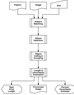
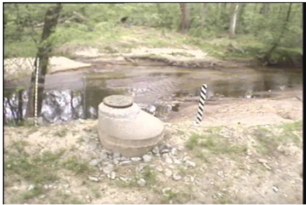
Figure 1 is the flow diagram of the algorithm. The output contains a pro-cessed image, the length of the pixels comprising a group of objects deemed to be our target marker (which is then normalized to water level in the driving perl script), and the confidence level. Figure 2 shows a sample image, before processing. Figure 3 shows the image after pattern matching, with brighter areas corresponding to a higher correlation coefficient. Finally, Figure 4 is the processed output. All the black areas have been thresholded below after the pattern matching. The blue areas have been rejected by object size criteria. The green areas have been rejected by object shape criteria. The red areas are objects which were not included in the final group. The line which represents the height has been superimposed with a red color.
Pattern Pattern Matching ROI Image Object Culling & Grouping Length & Uncertainty Estimation Object Detection Raw Pixel Length Percent Uncertainty Estimate Processed Image
Figure 1: The block diagram of the daytime water level detection algorithm
5.ii.
Implementation Details
The implementation is done in C++, conforming to the C99 ANSI/ISO stan-dard. An image processing library (ImageMagick) was used to handle images at
Figure 2: A sample image being processed – initial image
Figure 3: A sample image being processed – confidence levels
the lower levels. It is an open source library, which can be downloaded from the web at http://www.imagemagick.org. The library has various interfaces and the one used was the C++ wrapper, Magick++. The classes that perform all the necessary processing are defined in DayModule.h and implemented in Day-Module.C. The actual main() function is in the driver program, implemented in detect day.C.
5.iii.
Classes & Functions
class Point { //A 2D point public:
int x; //x coordinate int y; //y coordinate }
class Line { //A line on a 2D plane, defined by two points public: Point a; Point b; double slope(); double length(); } double Line::slope();
Description: calculates the (positive) slope of the line, normalized in the range
[0,pi]. mathematically this is not strictly correct, but when dealing with non-vector lines where the direction is not important, it is quite conve-nient.
Prerequisites:
NONE
Parameters:
NONE
Returns: the slope of the line
double Line::length();
Description: calculates the length of the line
Prerequisites:
NONE
NONE
Returns: the length of the line
class DayModule { public:
DayModule(); ~DayModule();
void process(Image pattern, double threshold); int findObjects();
int removeObjectsBySize(unsigned int min,unsigned int max);
int removeObjectsByShape(float slope, float slope_uncert, float width, float width_uncert); int removeObjectsByCorrelation(float distance, float slope);
pair<Line, float> determineHeight(); Image image;
void objectStatus(bool withdetails, bool withpoints); void matchPattern(Image pattern);
private:
typedef list<Point> ObjectType;
typedef map<int, ObjectType, less<int> > GroupType;
typedef map<int, GroupType, less<int> > GroupOfGroupsType; GroupType objects;
GroupOfGroupsType groups;
typedef map<int, Point, less<int> > MapOfPoints; MapOfPoints centers;
Image confidences;
Line largestDimension(ObjectType points, short steps); float averageWidth(ObjectType points, Line maxl); Point findCenter(ObjectType points);
};
DayModule::DayModule();
Description: default constructor
Prerequisites: NONE Parameters: NONE Returns: N/A DayModule:: DayModule();
Prerequisites:
NONE
Parameters:
NONE
Returns: N/A
void DayModule::process(Image pattern, double threshold);
Description: performs pattern matching & image processing.
Prerequisites:
NONE
Parameters:
pattern: the template to be matched, passed as a Magick++ Image class. threshold: the threshold above which a match is considered a success, in the
range ( )
Returns: void
int DayModule::findObjects();
Description: parses the image and detects separate objects (8 connected).
These will be stored in the private member DayModule::objects
Prerequisites:
• will only give good results when DayModule::process(pattern,
thresh-old) has been run before it.
Parameters:
NONE
Returns: the number of objects found.
int DayModule::removeObjectsBySize(unsigned int min, unsigned int max);
Description: removes objects from the ”objects” list based on the total
num-ber of pixels comprising the object. The removed objects are colored blue
Prerequisites:
• will not do anything unless findObjects() has been run before, to
Parameters:
min: objects having less than min pixels are removed. max: objects having more than max pixels are removed.
Returns: the number of objects removed.
int DayModule::removeObjectsByShape(float slope, float slope uncert, float width, float width uncert);
Description: removes objects from the ”objects” list based on the shape and
orientation of the object. NOTE: the width is calculated along the slope, on axes perpendicular to a line defined by the slope. The removed objects are colored green
Prerequisites:
• will not do anything unless findObjects() has been run before, to
populate the object list.
Parameters:
slope, slope uncert: anything with slope outside slope±slope uncert is removed. width, width uncert: anything with width outside width±width uncert is removed.
Returns: the number of objects removed.
int DayModule::removeObjectsByCorrelation(float distance, float slope);
Description: removes objects from the DayModule::objects list based on their
position relative to other objects. Objects are classified into groups ac-cording to their relative positions. The group with the most objects is the only one that remains. The removed objects are colored red
Prerequisites:
• will not do anything unless findObjects() has been run prior to it, to populate the object list
Parameters:
distance: the maximum distance between the center of two objects for them to qualify for the same group.
slope: the maximum relative slope between the center of two objects for them to qualify for the same group. This relative slope is defined as the angle between the line that passes from the two centers and the vertical axis.
pair<Line, float> DayModule::determineHeight();
Description: finds the biggest line that can be drawn between two members
of the current group of object. In addition, the line is drawn in the main image, with a red color and a width of two pixels.
Prerequisites:
• only makes sense when all irrelevant objects have been removed, so that the remaining ones form a group which is our candidate for the detected pole.
Parameters:
NONE
Returns: the line found, as a Line class, and the corresponding confidence level
as a float.
Image DayModule::image;
Description: the main image, stored as a Magick++ Image class
void DayModule::objectStatus(bool withdetails, bool withpoints);
Description: prints information about the current status of the objects
Prerequisites:
NONE
Parameters:
withdetails: when true, it will also give information about each object such as it center, its overall slope, the maximum width and the two endpoints of the object
withpoints: when true, it will also list every point comprising that object
Returns: void
typedef list<Point> DayModule::ObjectType;
Description: a list of points can define an object.
typedef map<int, ObjectType, less<int> > DayModule::GroupType;
Description: a
typedef map<int, GroupType, less<int> > DayModule::GroupOfGroupsType;
Description: a mapping of a group of objects to an index of groups.
GroupType DayModule::objects;
Description: the current list of candidate objects is stored here
GroupOfGroupsType DayModule::groups;
Description: the group each object was placed in is stored here.
typedef map<int, Point, less<int> > DayModule::MapOfPoints;
Description: a mapping of points to an index, so that the object index can be
used to map an object to a single point.
MapOfPoints DayModule::centers;
Description: the center of each object is stored here.
Image DayModule::confidences;
Description: the pattern matched image before thresholding is stored here, so
that the levels can later be used to determine the measure of confidence. The image is stored as a Magick++ Image class.
Line DayModule::largestDimension(ObjectType points, short steps);
Description: finds a line going through the two most distant points of an
object.
Prerequisites:
NONE
Parameters:
points: the Object (comprised of a list of points) whose largest dimension we want to determine.
steps: the number of steps will determine over how many axes the largest dimension is searched for. Since the projection of the points on each axis is used, this number can be small and the results will still be good. For example, when 8 steps are used even fairly complex objects will yield good results.
Returns: the line as a Line class
float DayModule::averageWidth(ObjectType points, Line maxl);
Description: finds the average width of an object, given a line that signifies
the ”height”.
Prerequisites:
NONE
Parameters:
points: the Object (comprised of a list of points) whose width we want to determine.
maxl: the line which specifies which dimension is considered as “height”, since “width” is a relative term. Note: maxl is typically the line returned by largestDimension.
Returns: the width of the line (in pixels)
void DayModule::matchPattern(Image pattern);
Description: performs the actual pattern matching. It will result in a grayscale
image, with the pixels that had a higher confidence being brighter. Note: this is the most time-consuming function throughout the class – for per-formance considerations, it pays off to have defined a region of interest as small as possible. Prerequisites: NONE Parameters: pattern: Returns: void
Algorithm: The correlation score is computed as:
r= v u u t [nPI M− (PI )PM ]2 h nPI2−(PI)2i hnPM2−(PM)2i
where n is the number of pixels in the template, I is the image and M is the template (model).
Description: finds the center of an object, calculated as an average of all its points.
Prerequisites:
NONE
Parameters:
points: the Object (comprised of a list of points) whose center we want to compute.
Returns: the center found, as a Point class.
5.iv.
Optimization
The daytime water level detection driver program accepts two adjustment pa-rameters from the command line. The first is the image template which will be used for correlation matching against the main image. The second is a region of interest, which is important for performance reasons since correlation matching is a computationally intensive process.
In addition to those, there are several parameters which are defined as con-stants in the main driver file. They are:
const double THRESHOLD_LEVEL=12000; const int OBJECT_MIN_SIZE=5;
const int OBJECT_MAX_SIZE=100; const float OBJECT_SLOPE=M_PI/4; const float OBJECT_SLOPE_UNCERT=0.4; const float OBJECT_WIDTH=1.0;
const float OBJECT_WIDTH_UNCERT=0.7; const float OBJECT_MAX_DISTANCE=20;
const float OBJECT_MAX_ANGLE_DEVIATION=M_PI/8;
The threshold level is used as a parameter to the process function, along with the pattern image. It indicates the level of correlation that is sufficient for a particular pixel to be considered a match.
The minimum and maximum object size are used by the removeObjectsBy-Size function. They determine the size range (in pixels) that is considered valid for a unique individual object.
The slope, width and their corresponding uncertainties are the ones used by the removeObjectsByShape function. The slope refers to the slope (in radians) of the largest diameter of the object and the accompanying uncertainty level is the acceptable scaling factor. The width refers to the average width of the object (in pixels) using the largest diameter to define the axis that determines “height”. The uncertainty is again the allowable linear scaling factor.
The maximum distance and maximum angle deviation are used by the re-moveObjectsByCorrelation function. The maximum distance is the distance (in
pixels) that is allowable between the centers of two objects for them to be poten-tially placed in the same group, thus possibly defining the group of objects that represent the measuring marker. The maximum angle deviation is the allowable angle (in radians) that the line defined between the centers of the two objects can form with the vertical axis, in other words to what extent can two objects be “leaning” for them to still qualify for the same group.
There should be no need for any of these to change, since they are defined in a generic way and should be able to match the target in under diverse condi-tions. The main reason that would prompt their change would be the hardware installation of a new, intrinsically different marker. A notable exception is the threshold level, which is dependent on the template image, so that a drastically different template might result in different correlation levels.
6.
Nighttime Detection Module
6.i.
Overview
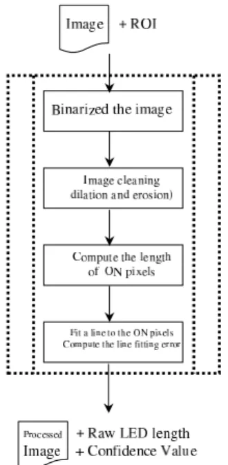
A PVC pipe with a vertical stripe of LEDs is installed. The LEDs are positioned directly towards the camera. With a high signal noise ratio, the nighttime water level detection algorithm is quite simple. We define a region of interest (ROI) to speed up the process and avoid false positives. Figure 5 is the flow diagram of the algorithm. The output contains a processed image, the length of the ON pixels (which will be converted to a normalized water level in the driving perl script), and the confidence value - the line fitting error. Figure 6 shows a sample image taken at the dawn be processed.
6.ii.
Implementation Details
We use an image IO utility (OpenIL) to load and save images. It is freely from the web at http://www.openil.org. The nighttime detection module is a stand alone C program. Its source contains three files, filter.C, filter.h, and night.C. night.C is the driver program that calls image processing functions that are implemented in filter.c. In filter.C, the following image processing functions are implemented.
6.iii.
Classes & Functions
void dilation(int w, int h, unsigned char * src, unsigned char * des);
Description: Perform image dilation using a 3x3 kernel
Prerequisites:
• the image must be a binary image; each pixel can only have two valid values, either zero or one.
Figure 5: Block diagram of the nighttime water level detection algorithm
Parameters:
w: image width h: image height
src: pointer to the source image; des: pointer to the destination image
Returns: void
void erosion(int w, int h, unsigned char * src, unsigned char * des);
Description: Perform image erosion using a 3x3 kernel
Prerequisites:
• the image must be a binary image, each pixel can only have two valid
values, either zero or one.
• The src and des pointers cannot be the same.
Parameters:
w: image width H: image height
Src: pointer to the source image Des: pointer to the destination image.
Returns: void
void binarize(int w, int h, unsigned char * src, unsigned char * des, float threshold);
Description: convert a gray scale image to a binary image
Prerequisites:
• the source image must be a gray scale image
Parameters:
w: image width H: image height
Src: pointer to the source image; Des: pointer to the destination image
Threshold: the threshold value, normalized between 0 and 1
void imfeature(int w, int h, unsigned char * src, FEATURES *fea);
Description: compute some image features. Right now, one only the length
of the feature and feature size (in pixels) are computed
Prerequisites:
• NONE
Parameters:
w: image width H: image height
Src: a pointer to the source image;
fea: a pointer to the FEATURES structure (defined below). Only the m top, m bottom and m pixCnt will be filled by this function.
Returns: void
void crop(int w, int h, unsigned char * src, int startx, int starty, int newW, int newH, unsigned char * des);
Description: crop the image.
Prerequisites:
• 0 ¡ startx ¡ w, 0¡ starty ¡ h; b) the image must be a single channel image, i.e. one byte per pixel.
Parameters:
w: image width H: image height
Src: pointer to the source image;
Startx, starty: the upper left corner of the cropped image NewW, newh: the dimension of the cropped image
Des: pointer to the cropped image
Returns: void
void fill(int w, int h, unsigned char * src, int startx, int starty, int newW, int newH, unsigned char * des);
Description: update a potion of the image with.
Prerequisites:
• 0 ¡ startx ¡ w, 0¡ starty ¡ h; b) the image must be a single channel
Parameters:
w: original image width H: original image height
Src: pointer to the image that will be replaced; Startx, starty: the upper left corner of the update region NewW, newh: the dimension of the update region;
Des: pointer to the pixel array that will replace the region in the original image
Returns: void
void MNCC(int w, int h, unsigned char * src, int pw, int ph, unsigned char * pattern, float * result);
Description: Perform normalized correlation using a custom-provided
tem-plate.
Prerequisites:
• the template must have odd sizes in both dimensions
• the image must be a single channel image, i.e. one byte per pixel
Parameters:
w: original image width H: original image height Src: pointer to the image; Pw, ph: the size of the template
pattern: pointer to the template’s array of pixels
result: pointer to a float array where the correlation score will be stored.
Returns: void
Algorithm: The correlation score is computed as:
r2= [n PI M− (PI )PM ]2 h nPI2−(PI)2i hnPM2−(PM)2i
where n is the number of pixels in the template, I is the image and M is the template (model).
float * fitLine(int w, int h, unsigned char * src, float * line);
Prerequisites:
• the image must be a binary image, each pixel can only have two valid
values, either zero or one.
• line must be an array that can at least hold four numbers.
Parameters:
w: image width H: image height
Src: pointer to the source image
line: pointer to the array that will hold the line parameters. The line is expressed in a parametric form. nx=t·line[0]+line[2]
y=t·line[1]+line[3]
o
, where t is a parameter.
Returns: void
float calDist(int w, int h, unsigned char * src, float * line);
Description: Fit the ON pixels to a line
Prerequisites:
• the image must be a binary image, each pixel can only have two valid
values, either zero or one.
Parameters:
w: image width H: image height
Src: pointer to the source image
Line: pointer to the array that holds the line parameters, in the same format as in function fitLine.
Returns: void
6.iv.
Optimization
The only user-defined values are the ROI and the threshold for binarize the image. While the ROI is supplied as a command line parameter, the threshold can only be changed at compile time. It is defined as a constant number in night.C. Usually, the default value (0.72) works fine. The binarization algorithm uses the threshold as a relative number to adjust to various lighting conditions. It is not recommended to change that value.
7.
Central Module
7.i.
Overview
The central module is the heart of the system. It invokes the image- processing modules, gets the water level and confidence measure from them and logs them to the database. It creates a web page reporting these values and sends out e-mail alerts when the water level crosses a threshold or when the confidence measure falls below a threshold.
7.ii.
Implementation Details
The central module is written in Perl - it acts like a wrapper around the image-processing modules which are in C++. A cron job is set up which calls this perl script every 10 minutes or at whatever frequency the system is to be executed. The perl script contains the function processImage which contains all the functionalities of the central module. Its prototype is of the form:
processImage( location, time)
Description:
• If the time was not passed as an argument, record the current time. • Call the function getInputImageFile which takes in the location of the input image file and the recorded time and returns the pathname of the input image file. If the file is on a remote machine, it transfers it using the unix program wget.
• Decide which image-processing module to call based on the time of day. During early morning and late evening, both day-time and night-time image- processing modules are called.
• Read the region-of-interest coordinates from the region-of-interest
configuration file.
• Call one or both image-processing modules. The arguments passed
are:
1. input file path name - the raw image from the camera in jpg format.
2. pattern file path name - pathname to the image to be used for the matching – only used with the day-time module.
3. output file path name - pathname to store the processed image. 4. Four region of interest coordinates - (x,y) of upper left corner,
width and height.
The module returns a string which contains two values separated by whitespace. The values returned are:
level: in terms of height of the object detected. The object is the LED in the night-time module and the yard-stick in the day-time module.
Confidence measure: a confidence value in percentage of the level as measured by the image-processing module.
• Normalize the level returned by the image-processing modules to
actual height of water level. This is done in the procedures nor-malizeNightModuleResult and normalizeDayModuleResult for night-time and day-night-time images respectively. When both modules are called, the returned values are combined to return one pair of wa-ter level and confidence measure in the procedure combineDayNight-ModuleResults.
• Open the database and read in the water level stored during the last
run of the software. If the difference between the current water level and the previous water level is greater than a threshold value, the confidence measure is changed to zero. The rationale for this is that it is not expected that the water level can change abruptly by more than the threshold value between two runs of the software. Such an abrupt change rather would indicate a catastrophic change in the setup - either the LEDs have blown or the yardstick is no more in the region of interest.
• Store the current water level and confidence measure in the database.
• If the current confidence measure is below a threshold, send mail to
the addresses listed in the setup-alert mailing list stating the current water level, confidence measure, status of the system and time. If specified, execute a user-provided script.
• If the current confidence measure is above the threshold and the water level is above a water-level threshold, send mail to addresses listed in the water-level alert mailing list. If specified, execute a user-provided script.
• Generate a web page reporting the current time, water-level and con-fidence measure and the actual image of the creek captured by the camera.
Prerequisites:
NONE
Parameters:
location: specifies the location of the raw image file captured by the camera at the creek. The image file can be either local or remote. If the camera stores images on the same machine on which this software runs, the file is local; otherwise the file is remote and must be transferred from the machine where it is stored.
time: is the time at which processImage was invoked. It is optional and if omitted, processImage calls the perl built-in function time to get the current time.
7.iii.
Normalizing Functions
normalizeDayModuleResult, normalizeNightModuleResult
Description: The height of the object detected by the image-processing
mod-ules needs to be transformed to actual height of water-level at the creek. These two functions provide that capability. This transformation can be done by either an algebraic formula or by reading a configuration file which can store the mapping between the height of detected object and height of water- level. Both modules take in the object height and confidence measure as arguments and return the water-level height and confidence measure as a string separated by whitespace.
combineDayNightModuleResults
Description: This procedure takes in two pairs of object height and confidence
measure returned by the two image-processing modules and first normal-izes them. If the confidence measures differ by more than 20 (they are percentages) the pair of water-level height and confidence measure corre-sponding to the higher one is returned. Otherwise, the mean water- level height and confidence measure is returned.
7.iv.
Global Definitions
All global variables used in the central module are defined in the file defini-tions.pl. Following is a list of global variables used in the central module:
DAYMODON: hour of day from which only day-time image processing
mod-ule will be called.
BOTHMODON: hour of day from which both day and night image processing
modules will be called.
NIGHTMODON: hour of day from which only night-time image processing
module will be called.
INPUTLOCAL: Flag specifying that input image file is on local machine
INPUTREMOTE: Flag specifying that input image file is on remote machine
ROOTDIR: Pathname of root directory of the Creekcam files.
INPUTIMAGEPATH: Pathname of directory in which input images grabbed
off the web are stored.
LOCALINPUTIMAGEPATH: Pathname of directory in which input
im-ages are stored by the creek camera.
ROICONFIGFILE: full pathname of configuration file storing the region of interest coordinates for the image processing modules.
INTERVAL MIN: Number of minutes between two runs of the software
DIFF LEVEL THRESHOLD: the threshold for the difference between two
consecutive water level readings. If the difference level is greater than this threshold, the software infers that there is something wrong with the setup.
CONF THRESHOLD: if the confidence is below this threshold, a setup alert
mail is sent and a user-provided script is executed.
LEVEL THRESHOLD: if the water level is above this threshold, a
water-level alert mail is sent and a user-provided script is executed.
OK: Status of setup is OK
CAMERA MOVED: A module detected that the camera has moved.
LOG GONE: The yardstick for the day-time image processing is not inside
the region-of-interest
LED BLOWN: The LEDs for the night-time image processing have blown
out
SETUP MAILLIST FILE: Full pathname of file containing email addresses
which must be alerted by mail when the confidence measure goes below threshold
ALERT MAILLIST FILE: Full pathname of file containing email addresses
which must be alerted by mail when the water level goes above threshold
SETUP MESG FILE: Full pathname of file containing template message for
setup alert mail.
ALERT MESG FILE: Full pathname of file containing template message for
water level alert mail.
MAILTEMP FILE: Full pathname of temporary file used to store mail body
while mailing
DAY MODULE: path name of day-time image processing executable
NIGHT MODULE: path name of night-time image processing executable
PATTERN TMPLT: path name of pattern template file used by day-time
8.
Web Module
The web module dynamically generates plots of water level against time ac-cording to user input through html forms and cgi-scripts. It also accepts email addresses to which the system will send water level alerts.
8.i.
Generating Plots
Plots of water level against time are generated dynamically using cgi- scripts written in perl and gnuplot. Three different scales on the time axis are supported - minutes, hour and day. The html forms for user input are in generateplot.html. The range of time is got from the html forms using the CGI POST method. The database is searched using the time range and a temporary data file is created. The script invokes gnuplot which reads the data file and produces the plot.
For plots of water level against time in hours or in days, the stored water level in the database is averaged over an hour or a day respectively before storing in the temporary data file for gnuplot.
8.ii.
Storing E-mail Addresses
People can submit their e-mail to get automated alerts when the water- level crosses a threshold. The cgi-script checks whether the email address already exists in the system or not. If it does, an error is reported and duplicate entries are not added. Right now, addresses can be removed from the list only by modifying the file directly - no user interface is provided to do that.