HEB 99, Cairo , Egypt, October 3 - 5 ,1999
EG0100178
HEATX :- A Computer Program for Rating and
Designing Shell and Tube Heat Exchangers.
Ahmed M Elhabrush
TNRC.
P.O. Box 30878 , Tripoli-Libya
A computer program was developed to be used as a quick tool for rating
shell and tube heat exchangers or searching for their optimum design. It
employs empirical relations for temperature differences across heat
transfer layers; the tube and shell fluids, the tube wall and the scale
layers. The optimum design is achieved when the sum of the temperature
differences approaches the logarithmic mean temperature difference
provided that the user's prescribed pressure drop limits are satisfied. To
accomplish this task, an iteration scheme was utilized.
Sample problems of heat exchanger designs in which the shell fluid
flows parallel to the tubes were cross checked using a coarse mesh
computer code TRANSG [3]. Also a shell and tube heat exchanger with
cross flow is rated. The results showed minor differences considering the
purpose for which this method is intended.
HEATX: A COMPUTER PROGRAM FOR RATING AND
DESIGNING SHELL AND TUBE HEAT EXCHANGERS .
Ahmed M. Elhabrush
TNRC
P.O. Box 30878 , Tripoli-Libya
ABSTRACT
A computer program was developed to be used as a quick tool for rating shell and tube heat exchangers or searching for their optimum design. It employs empirical relations for temperature differences across heat transfer layers; the tube and shell fluids, the tube wall and the scale layers. The optimum design is achieved when the sum of the temperature differences approaches the logarithmic mean temperature difference provided that the user's prescribed pressure drop limits are satisfied. To accomplish this task, an iteration scheme was utilized.
Sample problems of heat exchanger designs in which the shell fluid flows parallel to the tubes were cross checked using a coarse mesh computer code TRANSG [3]. Also a shell and tube heat exchanger with cross flow is rated. The results showed minor differences considering the purpose for which this method is intended.
Introduction: '>•
Designing a heat exchanger requires detailed thermalhydraulic calculations. For preliminary designs, simple methods may be used to predict the heat exchanger configuration capable of removing the specified heat without exceeding the imposed limits on the size, heat sink, pressure drop, etc. A quick method to rate and design heat exchangers based on the sum of the products SOP [4] was adopted in developing tliis program. In this method, the heat exchanger is considered to be composed of four heat transfer layers namely, the tube fluid, the tube wall, the scale and the shell fluid layers as shown in Fig. 1. The optimum design is obtained when the calculated
V$op value, which is the sum of the ratios of the temperature gradient across each
layer to the logarithmic mean temperature difference, approaches unity while satisfying the prescribed pressure drop limits. This condition is achieved by either varying the tube length to increase the heat transfer area or increasing the heat transfer coefficient by varying the baffle spacing according to the iterative scheme shown in Fig.2 .
The heat transfer through a film is expressed by the general convective heat equation:
q =hAAT (1)
Applying Eq.(l) to the four heat transfer layers shown in Fig.l assuming constant heat transfer areas, the steady state condition implies
q = h(AATt =hwAATw = hfAATf = hsAATs (2)
However, the heat transfer in heat exchangersis usually expressed in terms of the overall heat transfer coefficient U and the logarithmic mean temperature difference
ATm as
q = UAATm (3)
Where
+l(h5 ) (4)
Combining Eq. (2) and (3) , we get
= ATt / ATm + ATW I ATm + ATf I ATm + ATS I ATm - 1 (5)
The main objective of this program is determining the heat exchanger configuration such as the number of tubes , tubes length , and baffles spacing for which the V^op and the fluids pressure drops are within the user's prescribed limits . Empirical correlation for each term in the RHS of Eq. (5) for different flow conditions are given in reference(4).
Calculation
Procedures:-After reading the input data, thermalhydraulic parameters such as the fluid thermal properties, heat transfer surface area, hydraulic diameters, number of tubes, shell diameter are calculated. The subroutines SOPT, SOPW, SOPF, and SOPS are then
called to calculate the terms ATt I ATm, ATW I ATm, ATf I ATm, and ATS / ATm
respectively which are used in determining the Vgftp value. The pressure drops are
calculated in the SOPT and SOPS subroutines.
If the calculation task is rating the heat exchanger (IC=1), the results are printed and the task is terminated. If the task is designing a heat exchanger, an iterative procedure is implemented to satisfy the limits on the pressure drops and Vggp. The pressure drop is firstly satisfied by adjusting the number of tubes in the case of parallel flow. In the case of cross flow, the baffle spacing or both the baffle spacing and the number of tubes are adjusted depending on the option used. Once the pressure drops limits are satisfied, the V$op value is checked for convergence. If the V$QP is not within
Tig.!- Heoi "transfer layers READ Calc. V, A, y DATA | f l u i d prop., TN, Q,ATn C a l c . D , B , G , Dh TNT , V CALL SOPr
Fig.E- HEAT EXCHANGER CALC.,FLOW CHART
I: For Parallel Flow (1=1):
Since the pressure drop is proportional to the square of the fluid velocity which is proportional to the number of tubes, therefore the number of tubes that satisfies the pressure drop limit is calculated by
TNl+l = 73V, (APt I A Pm a x)0 5 AP, > AP, ( 6 ) = TN, (AP, / APr a a x)a 5 AP( <6PS ( 7
After satisfying the pressure drop limits, the Vgjp is checked for convergence. If it
is not within the limits, the tubes length is adjusted using the following equation:
- VSOP
In case the tube length limit Lmax is exceeded, the number of tubes is adjusted as given by Eqs. (6 and 7) and the iteration is continued till convergence is achieved .
II: For Cross Flow (1=2 )
In this case, two options are available to seek the convergence of both the pressure drop and Vg
First option
The pressure drop is satisfied by changing the number of tubes as in the parallel flow case. Consequently, this leads to changing the shell diameter. Since cross flow can be assumed if the baffle spacing is less than the shell diameter, the baffle spacing is calculated based on the user's choice to assure the adequacy of using cross flow correlation as follows,
After satisfying the pressure drop limits and the V$op is found to be beyond the limit,
the tubes length or the number of tubes is adjusted as in the parallel flow case.
Second option IB=2
In this option the tubes length is kept Constant, and the baffle spacing is calculated as follows,
(10)
If the pressure drop limit is satisfied while the V^gp convergence is not achieved, the
number of tubes is adjusted as follows
v
S0P. >i.o
v
S0P<i.o (12)
If a situation in which two consecutive calculations give one value of V$Qp greater
than one and an other less than one, the Secant method is used to predict TNlJr\ . It
may happen that the pressure drops in both the tubes and the shell reach the maximum
allowed pressure drop while the Vggp is not within the limits. In such case, an error message telling the user to modify either the tube length or the pressure drop limit is
printed and the task is terminated.
Sample
Problem:-To check the validity of the method, heat exchanger designs of different conditions were analyzed and only three cases will be presented.
Case-1:
A U-Tube heat exchanger having the parameters shown in Table 1.1 with the secondary fluid flowing parallel to the tubes is to be designed for three values of
pressure drop limits. The results of HEATX calculation for the parameters L,TN and D are shown in Table 1.2.
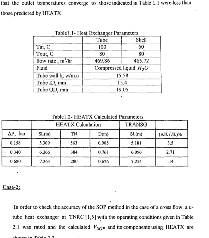
TRANSG code in which the heat exchanger is divided into cells and detailed thermalhydraulic calculation can be performed was used to check the accuracy of the HEATX calculations. As shown in the fifth column of Table 1.2, It was found that the shell length that should be used as an input to TRANSG code for the three cases so that the outlet temperatures converge to those indicated in Table 1.1 were less than those predicted by HEATX
Table 1.1 - Heat Exchanger Parameters
Tin, C Tout, C flow rate, m3/hr Fluid Tube wall k, w/m.c Tube ID, mm Tube OD, mm Tube 100 80 469.86 Shell 60 80 465.72 Compressed liquid HjO
15.58 15.4 19.05
Case-2:
Tablel .2- HEATX Calculated Parameters
AP, bar 0.158 -'• 0.340 0.680 HEATX Calculation SL(m) 5.369 6.266 7.264 TN 563 384 280 D(m) 0.905 0.761 0.626 TRANSG SL(m) 5.181 6.096 7.254 {hSLISL)% 3.5 2.71 .14
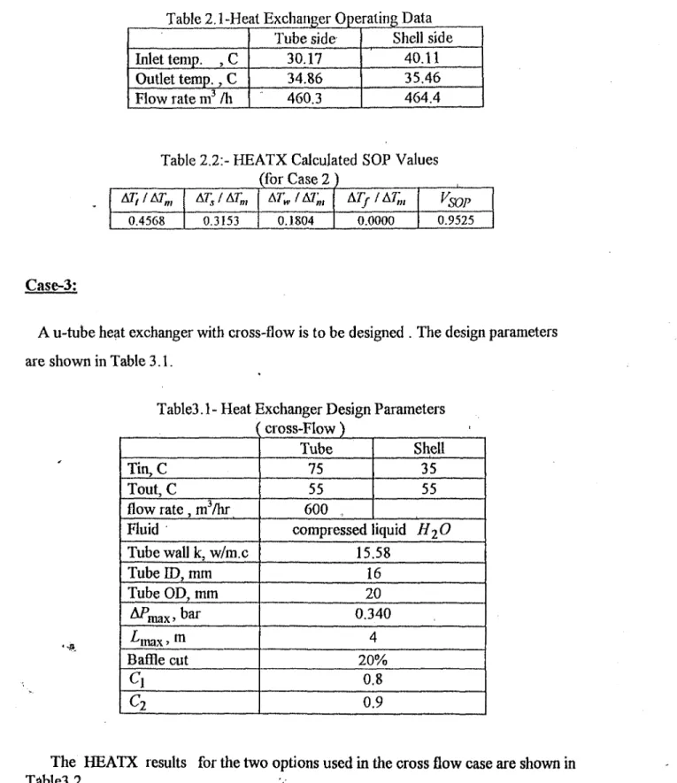
In order to check the accuracy of the SOP method in the case of a cross flow, a u-tube heat exchanger at TNRC [1,5] with the operating conditions given in Table 2.1 was rated and the calculated V$OP an^ 't s components using HEATX are
Table 2.1-Heat Exchanger Operating Data Inlet temp. , C Outlet temp., C Flow rate m3 /h Tube side 30.17 34.86 460.3 Shell side 40.11 35.46 464.4
Table 2.2:- HEATX Calculated SOP Values (for Case 2 ) &r,i&rm 0.4568 ATs/ATm 0.3153 ArM,/A7;, 0.1804 A7>/A7m 0.0000 VSOP 0.9525 Case-3;
A u-tube heat exchanger with cross-flow is to be designed . The design parameters are shown in Table 3.1.
• • » .
Table3.1 - Heat Exchanger Design ( cross-Flow ) Tin,C Tout, C flow rate, mVhr Fluid Tube wall k, w/m.c Tube ID, mm Tube OD, mm APma^bar -^max >m Baffle cut
c
2 Tube 75 55 600 , Parameters Shell 35 55 compressed liquid HiO15.58 16 20 0.340 4 20% 0.8 0.9
The HEATX results for the two options used in the cross flow case are shown in Table3.2.
Table 3.2- HEATX Out-put for Case3 IB 1 2 SL (m) 4.35 4.00 D(m) 0.925 0.981 B(m) 0.740 0.706 TN 531 601 AP,,bar 0.13 0.101 Aft,bar 0.34 0.34 83
Conclusion
:-Different heat exchangers with parallel flow were designed and rated using HEATX program and the calculations were cross checked using TRANSG code to confirm their adequacy in removing the heat for which they were designed. It was found that the tubes length calculated by HEATX program was about 4% greater than what is needed to achieve steady state conditions using TRANSG code for heat exchangers having equal fluid outlet temperature. The discrepancy increases as the difference between the outlet fluid temperatures increases. In the case of cross flow, it is evident that the SOP method overestimates the heat exchanger capability slightly giving a value of 0.9525 instead of one as shown in case 2. As far as the options in calculating the baffle spacing is concerned, the first option (IB=1) assures the validity of using cross flow correlation by selecting the appropriate constant Cj while the second option (IB=2) may lead to a baffle spacing greater than the shell diameter.
Considering its simplicity, this method is adequate in performing parametric studies to select the most appropriate heat exchanger design for further analysis using more sophisticated techniques. NOMENCLATURE:-A B C D h I IB L q SL TN w s AP AT
heat transfer area baffle spacing constant shell diameter
heat transfer coefficient flow index
baffle spacing calculation index tubelength
heat transferred shell length
number of tubes per pass tube wall error criterion pressure drop temperature drop •f i P s subscripts fouling iteration index pressure shell fluid tube fluid
References:
1- Heat Exchanger Type 1000 TH T -20 T 4-2, Technical Document, USSR, 1979 2- Knudsen and Katz, "Fluid Dynamics and Heat Transfer", Me Graw Hill, 1958, pp
324-520.
3- MM. Methnani " Nuclear Power Plant Simulation with Movable Boundary Steam Generator", Ph.D. Dissertation, U. of Michigan, 1983
4- R.C.Lord, P.E.Minton, arid R.P.Slusser, "Design of Heat Exchangers", Process Heat Exchange, Chemical Engineering, Me Graw Hill, 1979, ppl4-36.
5- Y.M.Yokhtin, " Engineering Physical Metallurgy and Heat Treatment.", Trans, by Nicholas Weinstein, MIR, Moscow, 1979 .