USER’S GUIDE
DEFAULT LOGIN DETAILS IP Address 192.168.1.1
Username admin
Hitron CDE-30364
VERSION 1.0ABOUT THIS USER’S GUIDE
INTENDED AUDIENCE
This manual is intended for people who want to configure the CDE-30364’s features via its Graphical User Interface (GUI).
HOW TO USE THIS USER’S GUIDE
This manual contains information on each the CDE-30364’s GUI screens, and describes how to use its various features.
Use the Introduction (page 15) to see an overview of the topics covered in this manual. Use the Table of Contents (page 7), List of Figures (page 11) and List of Tables(page 13) to quickly find information about a particular GUI screen or topic.
Use the Index (page 97) to find information on a specific keyword. Use the rest of this User’s Guide to see in-depth descriptions of the CDE-30364’s features.RELATED DOCUMENTATION
Quick Installation Guide: see this for information on getting your CDE-30364up and running right away. It includes information on system requirements, package contents, the installation procedure, and basic troubleshooting tips.
Online Help: each screen in the CDE-30364’s Graphical User Interface (GUI)contains a Help button. Click this button to see additional information about configuring the screen.
DOCUMENT CONVENTIONS
This User’s Guide uses various typographic conventions and styles to indicate content type:
1
Numbered paragraphs indicate procedural steps.NOTE: Notes provide additional information on a subject.
Warnings provide information about actions that could harm
you or your device.
Product labels, field labels, field choices, etc. are in bold type. For example:
A mouse click in the Graphical User Interface (GUI) is denoted by a right angle bracket ( > ). For example:
means that you should click Settings in the GUI, then Advanced settings. A key stroke is denoted by square brackets and uppercase text. For example:
CUSTOMER SUPPORT
For technical assistance or other customer support issues, please consult your Hitron representative.
USER’S GUIDE FEEDBACK
Please send all User’s Guide-related comments, questions or suggestions to
info@carliletech.com. Thank you!
Select UDP to use the User Datagram Protocol.
Click Settings > Advanced Settings.
Written by Rick Carlile.
Copyright 2011 Hitron Technologies. All rights reserved. All trademarks and registered trademarks used are the properties of their respective owners.
DISCLAIMER: The information in this User’s Guide is accurate at the time of writing. This User’s Guide is provided “as is” without express or implied warranty of any kind. Neither Hitron Technologies nor its agents assume any liability for inaccuracies in this User’s Guide, or losses incurred by use or misuse of the information in this User’s Guide.
TABLE OF CONTENTS
About This User’s Guide ... 3
Table of Contents... 7
List of Figures ... 11
List of Tables... 13
Introduction ... 15
1.1 CDE-30364 Overview ...15 1.1.1 Key Features ...15 1.2 Hardware Connections ...16 1.3 LEDs ...18 1.4 IP Address Setup ...201.4.1 Manual IP Address Setup ...20
1.5 Logging into the CDE-30364 ...21
1.6 GUI Overview ...22
1.7 Resetting the CDE-30364 ...23
Cable ... 25
2.1 Cable Overview ...25
2.1.1 DOCSIS ...25
2.1.2 IP Addresses and Subnets ...25
2.1.2.1 IP Address Format ...25 2.1.2.2 IP Address Assignment ...25 2.1.2.3 Subnets ...26 2.1.3 DHCP ...27 2.1.4 DHCP Lease ...28 2.1.5 MAC Addresses ...28
2.1.6 Routing Mode ... 28
2.1.7 Configuration Files ... 29
2.1.8 Downstream and Upstream Transmissions ... 29
2.1.9 Cable Frequencies ... 29
2.1.10 Modulation ... 29
2.1.11 TDMA, FDMA and SCDMA ... 30
2.2 The System Info Screen ... 30
2.3 The Initialization Screen ... 32
2.4 The Status Screen ... 33
2.5 The Event Log Screen ... 36
2.6 The Password Screen ... 37
LAN ... 39
3.1 LAN Overview ... 39
3.1.1 Local Area Networks ... 39
3.1.2 LAN IP Addresses and Subnets ... 39
3.1.3 Domain Suffix ... 40
3.1.4 Debugging (Ping and Traceroute) ... 40
3.2 The LAN IP Screen ... 40
3.3 The Switch Setup Screen ... 42
3.4 The Debug Screen ... 43
3.5 The Backup Screen ... 44
Firewall ... 47
4.1 Firewall Overview ... 47
4.1.1 Firewall ... 47
4.1.2 Intrusion detection system ... 47
4.1.3 Ping ... 47 4.1.4 MAC Filtering ... 47 4.1.5 IP Filtering ... 48 4.1.6 Port Forwarding ... 48 4.1.7 Port Triggering ... 48 4.1.8 DMZ ... 48
4.2 The Firewall Options Screen ... 49
4.3 The MAC Filtering Screen ... 50
4.4 The IP Filtering Screen ... 53
4.4.1 Adding or Editing an IP Filtering Rule ... 54
4.5 The Forwarding Screen ... 56
4.6.1 Adding or Editing a Port Triggering Rule ...61
4.7 The Local Logs Screen ...63
Parental Control ... 65
5.1 Parental Control Overview ...65
5.1.1 Website Blocking ...65
5.2 The Web Site Blocking Screen ...65
5.3 The Scheduling Screen ...67
5.4 The Local Logs Screen ...69
Wireless ... 71
6.1 Wireless Overview ...71
6.1.1 Wireless Networking Basics ...71
6.1.2 Architecture ...71
6.1.3 Wireless Standards ...71
6.1.4 Service Sets and SSIDs ...72
6.1.5 Wireless Security ...72
6.1.5.1 WPS ...73
6.1.6 WMM ...73
6.2 The Basic Screen ...73
6.3 The Security Screen ...76
6.4 The Access Control Screen ...79
6.5 The Advanced Screen ...81
6.5.1 Configuring WMM Parameters ...87
6.6 The WiFi Site Survey Screen ...90
Troubleshooting... 93
LIST OF FIGURES
FIGURE 1: Application Overview ...15
FIGURE 2: Hardware Connections ...17
FIGURE 3: LEDs ...19
FIGURE 4: Login ...22
FIGURE 5: GUI Overview ...22
FIGURE 6: The Cable > System Info Screen ...31
FIGURE 7: The Cable > Initialization Screen ...33
FIGURE 8: The Cable > Status Screen ...34
FIGURE 9: The Cable > Event Log Screen ...36
FIGURE 10: The Cable > Password Screen ...37
FIGURE 11: The LAN > LAN IP Screen ...41
FIGURE 12: The LAN > Switch Setup Screen ...43
FIGURE 13: The LAN > Debug Screen ...44
FIGURE 14: The LAN > Backup Screen ...44
FIGURE 15: The Firewall > Firewall Options Screen ...49
FIGURE 16: The Firewall > MAC Filtering Screen ...51
FIGURE 17: The Firewall > IP Filtering Screen ...53
FIGURE 18: The Firewall > IP Filtering > Add/Edit Screen ...55
FIGURE 19: The Firewall > Forwarding Screen ...56
FIGURE 20: The Firewall > Forwarding > Add/Edit Screen ...58
FIGURE 21: The Firewall > Port Triggering Screen ...60
FIGURE 22: The Firewall > Port Triggering > Add/Edit Screen ...61
FIGURE 23: The Firewall > Local Logs Screen ...63
FIGURE 24: The Parent Control > Web Site Blocking Screen ...66
FIGURE 25: The Parent Control > Scheduling Screen ...68
FIGURE 26: The Parent Control > Local Logs Screen ...69
FIGURE 27: The Wireless > Basic Screen ...74
FIGURE 28: WPS PIN ...75
FIGURE 29: The Wireless > Security Screen ...76
FIGURE 32: The Wireless > Advanced > WMM Configuration Screen ... 87 FIGURE 33: The Wireless > WiFi Site Survey Screen ... 90
LIST OF TABLES
TABLE 1: Hardware Connections ...17
TABLE 2: LEDs ...19
TABLE 3: GUI Overview ...23
TABLE 4: Private IP Address Ranges ...26
TABLE 5: IP Address: Decimal and Binary ...27
TABLE 6: Subnet Mask: Decimal and Binary ...27
TABLE 7: The Cable > System Info Screen ...31
TABLE 8: The Cable > Status Screen ...34
TABLE 9: The Cable > Event Log Screen ...36
TABLE 10: The Cable > Password Screen ...37
TABLE 11: The LAN > LAN IP Screen ...41
TABLE 12: The LAN > Switch Setup Screen ...43
TABLE 13: The LAN > Debug Screen ...44
TABLE 14: The LAN > Backup Screen ...45
TABLE 15: The Firewall > Firewall Options Screen ...49
TABLE 16: The Firewall > MAC Filtering Screen ...51
TABLE 17: The Firewall > IP Filtering Screen ...53
TABLE 18: The Firewall > IP Filtering > Add/Edit Screen ...55
TABLE 19: The Firewall > Forwarding Screen ...56
TABLE 20: The Firewall > Forwarding > Add/Edit Screen ...58
TABLE 21: The Firewall > Port Triggering Screen ...60
TABLE 22: The Firewall > Port Triggering > Add/Edit Screen ...62
TABLE 23: The Firewall > Local Logs Screen ...63
TABLE 24: The Parent Control > Web Site Blocking Screen ...66
TABLE 25: The Parent Control > Scheduling Screen ...68
TABLE 26: The Parental Control > Local Logs Screen ...69
TABLE 27: The Wireless > Basic Screen ...74
TABLE 28: The Wireless > Security Screen ...77
TABLE 29: The Wireless > Access Control Screen ...80
1
INTRODUCTION
This chapter introduces the CDE-30364 and its GUI (Graphical User Interface).1.1
CDE-30364 OVERVIEW
Your CDE-30364 is a NAT-capable cable modem and wireless access point that allows you to connect your computers, wireless devices, and other network devices to one another, and to the Internet via the cable connection.
Computers with a wired connection to the CDE-30364 are on the Local Area Network (LAN), computers with a wireless connection to the CDE-30364 are on the Wireless Local Area Network (WLAN) and the CDE-30364 connects to the service provider over the Wide Area Network (WAN).
FIGURE 1: Application Overview
1.2
HARDWARE CONNECTIONS
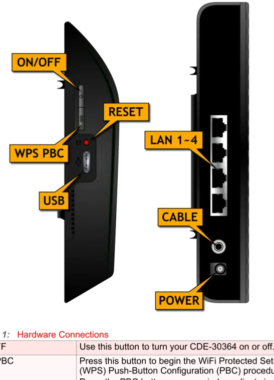
FIGURE 2: Hardware Connections
TABLE 1: Hardware Connections
ON/OFF Use this button to turn your CDE-30364 on or off. WPS PBC Press this button to begin the WiFi Protected Setup
(WPS) Push-Button Configuration (PBC) procedure. Press the PBC button on your wireless clients in the coverage area within two minutes to enable them to join the wireless network.
1.3
LEDS
This section describes the CDE-30364’s LEDs (lights).
Reset Use this button to reboot or reset your CDE-30364.
Press the button and hold it for less than fiveseconds to reboot the CDE-30364. The CDE-30364 restarts, using your existing settings.
Press the button and hold it for more than ten seconds to delete all user-configured settings and restart the CDE-30364 using its factory default settings.USB At the time of writing, this port is reserved for future use. LAN1 Use these ports to connect your computers and other
network devices, using Category 5 or 6 Ethernet cables with RJ45 connectors.
LAN2 LAN3 LAN4
CATV Use this to connect to the Internet via an F-type RF cable.
12VDC Use this to connect to the 12v/1.5A power adapter that came with your CDE-30364.
NEVER use another power adapter with
your CDE-30364. Doing so could harm
your CDE-30364.
FIGURE 3: LEDs
TABLE 2: LEDs
LED STATUS DESCRIPTION
WIRELESS Off No data is being transmitted or received over the wireless network.
Blinking Data is being transmitted or received over the wireless network.
ETH 1~4 Off No device is connected to the relevant LAN port. Blinking A device is connected to the relevant LAN port via a
fast Ethernet link, and is transmitting or receiving data.
On A device is connected to the relevant LAN port via a fast ethernet link, but is not transmitting or receiving data.
Status Blinking The CDE-30364’s cable modem is registering with the service provider.
On The CDE-30364’s cable modem has successfully registered with the service provider.
US Blinking The CDE-30364 is searching for an upstream frequency on the CATV connection.
On The CDE-30364 has successfully located and locked onto an upstream frequency on the CATV
1.4
IP ADDRESS SETUP
Before you log into the CDE-30364’s GUI, your computer’s IP address must be in the same subnet as the CDE-30364. This allows your computer to communicate with the CDE-30364.
NOTE: See IP Addresses and Subnets on page 25 for background information.
The CDE-30364 has a built-in DHCP server that, when active, assigns IP addresses to computers on the LAN. When the DHCP server is active, you can get an IP
address automatically. The DHCP server is active by default.
If your computer is configured to get an IP address automatically, or if you are not sure, try to log in to the CDE-30364 (see Logging into the CDE-30364 on page 21).
If the login screen displays, your computer is already configured correctly. If the login screen does not display, either the CDE-30364’s DHCP server is not active or your computer is not configured correctly. Follow the procedure inManual IP Address Setup on page 20 and set your computer to get an IP address automatically. Try to log in again. If you cannot log in, follow the manual IP address setup procedure again, and set a specific IP address as shown. Try to log in again.
NOTE: If you still cannot see the login screen, your CDE-30364’s IP settings may have been changed from their defaults. If you do not know the CDE-30364’s new address, you should return it to its factory defaults. See Resetting the CDE-30364 on page 23. Bear in mind that ALL user-configured settings are lost.
1.4.1
MANUAL IP ADDRESS SETUP
By default, your CDE-30364’s local IP address is 192.168.1.1. If your CDE-30364 is using the default IP address, you should set your computer’s IP address to be between 192.168.1.2 and 192.168.1.254.
NOTE: If your CDE-30364 DHCP server is active, set your computer to get an IP address automatically in step 5. The CDE-30364 assigns an IP address to
DS Blinking The CDE-30364 is searching for a downstream frequency on the CATV connection.
On The CDE-30364 has successfully located and locked onto a downstream frequency on the CATV
connection.
Power On The CDE-30364 is receiving power. Off The CDE-30364 is not receiving power.
Take the following steps to manually set up your computer’s IP address to connect to the CDE-30364:
NOTE: This example uses Windows XP; the procedure for your operating system may be different.
1
Click Start, then click Control Panel.2
In the window that displays, double-click Network Connections.3
Right-click your network connection (usually Local Area Connection) and clickProperties.
4
In the General tab’s This connection uses the following items list, scroll down and select Internet Protocol (TCP/IP). Click Properties.5
You can get an IP address automatically, or specify one manually: If your CDE-30364’s DHCP server is active, select Get an IP addressautomatically.
If your CDE-30364’s DHCP server is active, select Use the following IPaddress. In the IP address field, enter a value between 192.168.1.2 and
192.168.1.254 (default). In the Subnet mask field, enter 255.255.255.0
(default).
NOTE: If your CDE-30364 is not using the default IP address, enter an IP address and subnet mask that places your computer in the same subnet as the CDE-30364.
6
Click OK. The Internet Protocol (TCP/IP) window closes. In the Local AreaConnection Properties window, click OK.
Your computer now obtains an IP address from the CDE-30364, or uses the IP address that you specified, and can communicate with the CDE-30364.
1.5
LOGGING INTO THE CDE-30364
Take the following steps to log into the CDE-30364’s GUI.
NOTE: You can log into the CDE-30364’s GUI via the wireless interface. However, it is strongly recommended that you configure the CDE-30364 via a wired connection on the LAN.
1
Open a browser window.2
Enter the CDE-30364’s IP address (default 192.168.1.1) in the URL bar. TheFIGURE 4: Login
3
Enter the Username and Password. The default login username is admin, and the default password is admin.NOTE: The Username and Password are case-sensitive; “admin” is not the same as “Admin”.
4
Click Login. The System Info screen displays (see The System Info Screen on page 30).1.6
GUI OVERVIEW
This section describes the CDE-30364’s GUI.
1.7
RESETTING THE CDE-30364
When you reset the CDE-30364 to its factory defaults, all user-configured settings are lost, and the CDE-30364 is returned to its initial configuration state.
There are two ways to reset the CDE-30364:
Press the RESET button on the CDE-30364, and hold it in for ten seconds or longer. Click LAN > Backup. In the screen that displays, click the Factory Resetbutton.
The CDE-30364 turns off and on again, using its factory default settings.
NOTE: Depending on your CDE-30364’s previous configuration, you may need to re-configure your computer’s IP settings; see IP Address Setup on page 20.
TABLE 3: GUI Overview
Primary
Navigation Bar Use this section to move from one part of the GUI to another. Secondary
Navigation Bar Use this section to move from one related screen to another. Main Window Use this section to read information about your CDE-30364’s
2
CABLE
This chapter describes the screens that display when you click Cable in the toolbar.2.1
CABLE OVERVIEW
This section describes some of the concepts related to the Cable screens.
2.1.1
DOCSIS
The Data Over Cable Service Interface Specification (DOCSIS) is a
telecommunications standard that defines the provision of data services) Internet access) over a traditional cable TV (CATV) network.
Your CDE-30364 supports DOCSIS version 3.0.
2.1.2
IP ADDRESSES AND SUBNETS
Every computer on the Internet must have a unique Internet Protocol (IP) address. The IP address works much like a street address, in that it identifies a specific
location to which information is transmitted. No two computers on a network can have the same IP address.
2.1.2.1 IP ADDRESS FORMAT
IP addresses consist of four octets (8-bit numerical values) and are usually
represented in decimal notation, for example 192.168.1.1. In decimal notation, this means that each octet has a minimum value of 0 and a maximum value of 255. An IP address carries two basic pieces of information: the “network number” (the address of the network as a whole, analogous to a street name) and the “host ID” (analogous to a house number) which identifies the specific computer (or other network device).
2.1.2.2 IP ADDRESS ASSIGNMENT
IP addresses can come from three places:IANA is responsible for IP address allocation on a global scale, and your ISP assigns IP addresses to its customers. You should never attempt to define your own IP addresses on a public network, but you are free to do so on a private network. In the case of the CDE-30364:
The public network (Wide Area Network or WAN) is the link between the cable (CATV) connector and your Internet Service Provider. Your CDE-30364’s IP address on this network is assigned by your service provider. The private network (in routing mode - see Routing Mode on page 28) is your Local Area Network (LAN) and Wireless Local Area Network (WLAN), if enabled. You are free to assign IP addresses to computers on the LAN and WLAN manually, or to allow the CDE-30364 to assign them automatically via DHCP (Dynamic Host Configuration Protocol). IANA has reserved the following blocks of IP addresses to be used for private networks only:If you assign addresses manually, they must be within the CDE-30364’s LAN subnet.
2.1.2.3 SUBNETS
A subnet (short for sub-network) is, as the name suggests, a separate section of a network, distinct from the main network of which it is a part. A subnet may contain all of the computers at one corporate local office, for example, while the main network includes several offices.
In order to define the extent of a subnet, and to differentiate it from the main network, a subnet mask is used. This “masks” the part of the IP address that refers to the main network, leaving the part of the IP address that refers to the sub-network.
Each subnet mask has 32 bits (binary digits), as does each IP address:
A binary value of 1 in the subnet mask indicates that the corresponding bit in the IP address is part of the main network. A binary value of 0 in the subnet mask indicates that the corresponding bit in the IP address is part of the sub-network.TABLE 4: Private IP Address Ranges
FROM... ...TO
10.0.0.0 10.255.255.255 172.16.0.0 172.31.255.255 192.168.0.0 192.168.255.255
For example, the following table shows the IP address of a computer (192.168.1.1) expressed in decimal and binary (each cell in the table indicates one octet):
The following table shows a subnet mask that “masks” the first twenty-four bits of the IP address, in both its decimal and binary notation.
This shows that in this subnet, the first three octets (192.168.1, in the example IP address) define the main network, and the final octet (1, in the example IP address) defines the computer’s address on the subnet.
The decimal and binary notations give us the two common ways to write a subnet mask:
Decimal: the subnet mask is written in the same fashion as the IP address:255.255.255.0, for example.
Binary: the subnet mask is indicated after the IP address (preceded by a forward slash), specifying the number of binary digits that it masks. The subnet mask255.255.255.0 masks the first twenty-four bits of the IP address, so it would be
written as follows: 192.168.1.1/24.
2.1.3
DHCP
The Dynamic Host Configuration Protocol, or DHCP, defines the process by which IP addresses can be assigned to computers and other networking devices
automatically, from another device on the network. This device is known as a DHCP server, and provides addresses to all the DHCP client devices.
In order to receive an IP address via DHCP, a computer must first request one from the DHCP server (this is a broadcast request, meaning that it is sent out to the whole network, rather than just one IP address). The DHCP server hears the requests, and responds by assigning an IP address to the computer that requested it.
If a computer is not configured to request an IP address via DHCP, you must
configure an IP address manually if you want to access other computers and devices on the network. See IP Address Setup on page 20 for more information.
By default, the CDE-30364 is a DHCP client on the WAN (the CATV connection). It broadcasts an IP address over the cable network, and receives one from the service provider. By default, the CDE-30364 is a DHCP server on the LAN; it provides IP addresses to computers on the LAN which request them.
TABLE 5: IP Address: Decimal and Binary
192 168 0 1
11000000 10101000 00000000 00000001
TABLE 6: Subnet Mask: Decimal and Binary
255 255 255 0
2.1.4
DHCP LEASE
“DHCP lease” refers to the length of time for which a DHCP server allows a DHCP client to use an IP address. Usually, a DHCP client will request a DHCP lease renewal before the lease time is up, and can continue to use the IP address for an additional period. However, if the client does not request a renewal, the DHCP server stops allowing the client to use the IP address.
This is done to prevent IP addresses from being used up by computers that no longer require them, since the pool of available IP addresses is finite.
2.1.5
MAC ADDRESSES
Every network device possesses a Media Access Control (MAC) address. This is a unique alphanumeric code, given to the device at the factory, which in most cases cannot be changed (although some devices are capable of “MAC spoofing”, where they impersonate another device’s MAC address).
MAC addresses are the most reliable way of identifying network devices, since IP addresses tend to change over time (whether manually altered, or updated via DHCP).
Each MAC address displays as six groups of two hexadecimal digits separated by colons (or, occasionally, dashes) for example 00:AA:FF:1A:B5:74.
NOTE: Each group of two hexadecimal digits is known as an “octet”, since it represents eight bits.
Bear in mind that a MAC address does not precisely represent a computer on your network (or elsewhere), it represents a network device, which may be part of a computer (or other device). For example, if a single computer has an Ethernet card (to connect to your CDE-30364 via one of the LAN ports) and also has a wireless card (to connect to your CDE-30364 over the wireless interface) the MAC addresses of the two cards will be different. In the case of the CDE-30364, each internal module (cable modem module, Ethernet module, wireless module, etc.) possesses its own MAC address.
2.1.6
ROUTING MODE
When your CDE-30364 is in routing mode, it acts as a gateway for computers on the LAN to access the Internet. The service provider assigns an IP address to the CDE-30364 on the WAN, and all traffic for LAN computers is sent to that IP address. The CDE-30364 assigns private IP addresses to LAN computers (when DHCP is active), and transmits the relevant traffic to each private IP address.
NOTE: When DHCP is not active on the CDE-30364 in routing mode, each computer on the LAN must be assigned an IP address in the CDE-30364’s subnet manually.
When the CDE-30364 is not in routing mode, the service provider assigns an IP address to each computer connected to the CDE-30364 directly. The CDE-30364 does not perform any routing operations, and traffic flows between the computers and the service provider.
Routing mode is not user-configurable; it is specified by the service provider in the CDE-30364’s configuration file.
2.1.7
CONFIGURATION FILES
The CDE-30364’s configuration (or config) file is a document that the CDE-30364 obtains automatically over the Internet from the service provider’s server, which specifies the settings that the CDE-30364 should use. It contains a variety of settings that are not present in the user-configurable Graphical User Interface (GUI) and can be specified only by the service provider.
2.1.8
DOWNSTREAM AND UPSTREAM TRANSMISSIONS
The terms “downstream” and “upstream” refer to data traffic flows, and indicate the direction in which the traffic is traveling. “Downstream” refers to traffic from the service provider to the 30364, and “upstream” refers to traffic from the CDE-30364 to the service provider.
2.1.9
CABLE FREQUENCIES
Just like radio transmissions, data transmissions over the cable network must exist on different frequencies in order to avoid interference between signals.
The data traffic band is separate from the TV band, and each data channel is separate from other data channels.
2.1.10
MODULATION
Transmissions over the cable network are based on a strong, high frequency periodic waveform known as the “carrier wave.” This carrier wave is so called because it “carries” the data signal. The data signal itself is defined by variations in the carrier wave. The process of varying the carrier wave (in order to carry data signal
information) is known as “modulation.” The data signal is thus known as the “modulating signal.”
Cable transmissions use a variety of methods to perform modulation (and the “decoding” of the received signal, or “demodulation”). The modulation methods defined in DOCSIS 3 are as follows:
QPSK: Quadrature Phase-Shift Keying QAM: Quadrature Amplitude ModulationIn many cases, a number precedes the modulation type (for example 16 QAM). This number refers to the complexity of modulation. The higher the number, the more data can be encoded in each symbol.
NOTE: In modulated signals, each distinct modulated character (for example, each audible tone produced by a modem for transmission over telephone lines) is known as a symbol.
Since more information can be represented by a single character, a higher number indicates a higher data transfer rate.
2.1.11
TDMA, FDMA AND SCDMA
Time Division Multiple Access (TDMA), Frequency Division Multiple Access (FDMA) and Synchronous Code Division Multiple Access (SCDMA) are channel access methods that allow multiple users to share the same frequency channel.
TDMA allows multiple users to share the same frequency channel by splitting transmissions by time. Each user is allocated a number of time slots, and transmits during those time slots. FDMA allows multiple users to share the same frequency channel by assigning a frequency band within the existing channel to each user. SCDMA allows multiple users to share the same frequency channel by assigning a unique orthogonal code to each user.2.2
THE SYSTEM INFO SCREEN
Use this screen to see general information about your CDE-30364’s hardware, its software, and its connection to the Internet.
NOTE: Most of the information that displays in this screen is for troubleshooting purposes only. However, you may need to use the MAC Address information when setting up your network.
FIGURE 6: The Cable > System Info Screen
The following table describes the labels in this screen.
TABLE 7: The Cable > System Info Screen
General Information Vendor
Identification This displays the name of the company that supplied the CDE-30364. Model Name This displays the device’s model name (CDE-30364). DOCSIS Mode This displays the version of the Data Over Cable Service
Interface Specification (DOCSIS) standard to which the CDE-30364 complies.
HW Version This displays the version number of the CDE-30364’s physical hardware.
SW Version This displays the version number of the software that controls the CDE-30364.
Boot ROM Version This displays the version number of the program that controls the CDE-30364’s boot procedure (in which the main software is loaded).
MAC Address
RF MAC Address This displays the Media Access Control (MAC) address of the CDE-30364’s RF module. This is the module that connects to the Internet through the CATV connection. Ethernet MAC
Address This displays the Media Access Control (MAC) address of the CDE-30364’s Ethernet module. This is the module to which you connect through the LAN ports.
WAN MAC Address
(in Routing Mode This displays the Media Access Control (MAC) address of the module that connects to the Internet through the CATV
2.3
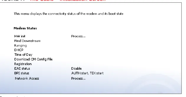
THE INITIALIZATION SCREEN
This screen displays the steps successfully taken to connect to the Internet over the
CATV connection.
Use this screen for troubleshooting purposes to ensure that the CDE-30364 has successfully connected to the Internet; if an error has occurred you can identify the stage at which the failure occurred.
NOTE: This screen displays when you first log in to the CDE-30364.
Click Cable > Initialization. The following screen displays. Primary BSSID
MAC Address This displays the Media Access Control (MAC) address of the CDE-30364’s Basic Service Set IDentifier (BSSID). This is the MAC address of the wireless module to which wireless clients connect.
NOTE: You may have additional BSSIDs, depending on your contract with your service provider.
System Time This displays the current date and time.
System Uptime This displays the number of days, hours, minutes and seconds since the CDE-30364 was last switched on or rebooted.
Network Access This field displays when you are connected to your service provider, and shows whether or not your service provider allows you to access the Internet over the CATV
connection.
Permitted displays if you can access the Internet. Denied displays if you cannot access the Internet.FIGURE 7: The Cable > Initialization Screen
For each step:
Process displays when the CDE-30364 is attempting to complete a connectionstep.
Success displays when the CDE-30364 has completed a connection step.2.4
THE STATUS SCREEN
Use this screen to discover information about:
The nature of the upstream and downstream connection between the CDE-30364 and the device to which it is connected through the CATV interface. IP details of the CDE-30364’s WAN connection.You can also configure the CDE-30364’s downstream center frequency. Click Cable > Status. The following screen displays.
FIGURE 8: The Cable > Status Screen
The following table describes the labels in this screen.
TABLE 8: The Cable > Status Screen
CM Configuration File
Name This displays the name of the configuration file that the CDE-30364 downloaded from your service provider. This file provides the CDE-30364 with the service parameter data that it needs to perform its functions correctly.
Network Access This displays whether or not your service provider allows you to access the Internet over the CATV connection.
Permitted displays if you can access the Internet. Denied displays if you cannot access the Internet.Downstream
Frequency to Tune to This displays the current center frequency in Hertz (Hz) over which data is transmitted to the CDE-30364 over the CATV interface. This is the frequency to which the CDE-30364 is locked in; it will only scan for another frequency if this frequency becomes unavailable. If you want the CDE-30364 to attempt to connect at a different frequency, enter it in the field and click Apply.
NOTE: Do not change the frequency unless you have a good reason to do so.
Scanning Start
Frequency This displays the frequency in Hertz (Hz) at which the CDE-30364 begins scanning for a connection over the
CATV interface (if a frequency is not already locked in). Channel Frequency This displays the actual frequency of each downstream
data channel to which the CDE-30364 is connected. Modulation This displays the type of modulation that each
downstream channel uses. Possible modulation types Signal Strength This displays the power of the signal of each
downstream data channel to which the CDE-30364 is connected, in dBmV (decibels above/below 1 millivolt). Signal Noise Ratio This displays the Signal to Noise Ratio (SNR) of each
downstream data channel to which the CDE-30364 is connected, in dB (decibels).
Upstream
NOTE: The upstream signal is the signal transmitted from the CDE-30364.
Channel ID This displays the ID number of each channel on which the upstream signal is transmitted.
Upstream Frequency This displays the frequency in Herz (Hz) of each upstream data channel to which the CDE-30364 is connected.
Upstream Bandwidth This displays the bandwidth of each upstream data channel to which the CDE-30364 is connected (in Hertz). SCDMA Mode This displays the Synchronous Code Division Multiple
Access (SCDMA) mode of each channel on which the upstream signal is transmitted.
Transmission Signal
Strength This displays the transmitted power of the signal of each upstream data channel to which the CDE-30364 is connected, in dBmV (decibels above/below 1 millivolt). Cable Modem IP Information
IP Address This displays the CDE-30364’s WAN IP address. This IP address is automatically assigned to the CDE-30364 Subnet Mask This displays the CDE-30364’s WAN subnet mask.
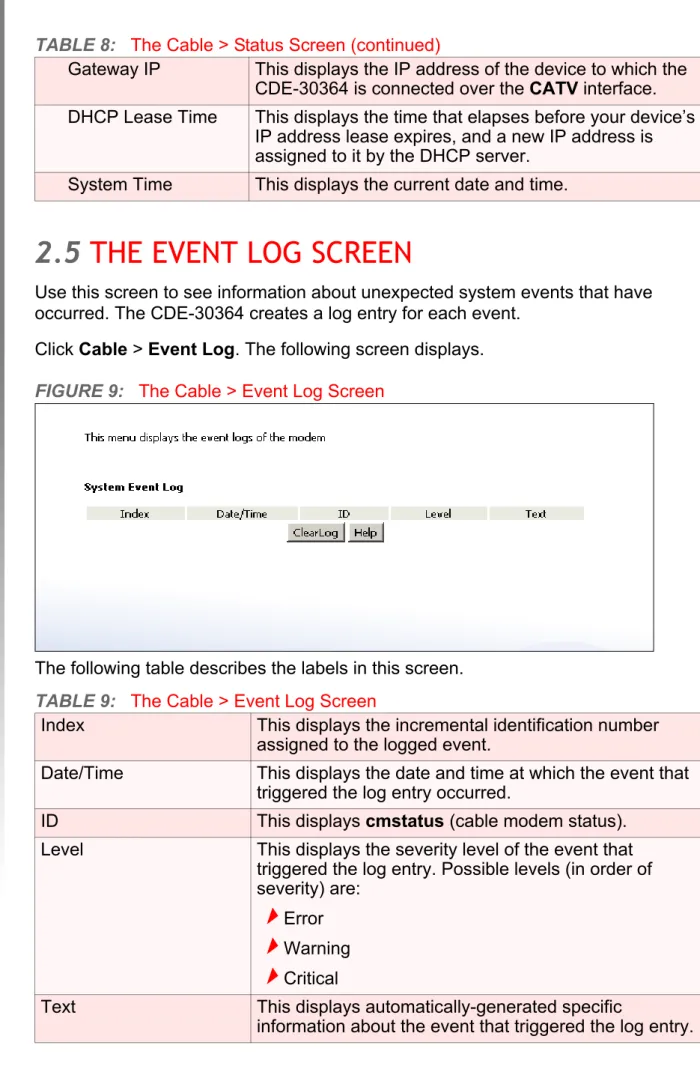
2.5
THE EVENT LOG SCREEN
Use this screen to see information about unexpected system events that have occurred. The CDE-30364 creates a log entry for each event.
Click Cable > Event Log. The following screen displays.
FIGURE 9: The Cable > Event Log Screen
The following table describes the labels in this screen.
Gateway IP This displays the IP address of the device to which the CDE-30364 is connected over the CATV interface. DHCP Lease Time This displays the time that elapses before your device’s
IP address lease expires, and a new IP address is assigned to it by the DHCP server.
System Time This displays the current date and time.
TABLE 9: The Cable > Event Log Screen
Index This displays the incremental identification number assigned to the logged event.
Date/Time This displays the date and time at which the event that triggered the log entry occurred.
ID This displays cmstatus (cable modem status). Level This displays the severity level of the event that
triggered the log entry. Possible levels (in order of severity) are:
Error Warning CriticalText This displays automatically-generated specific
information about the event that triggered the log entry.
2.6
THE PASSWORD SCREEN
Use this screen to change the password with which you log in to the CDE-30364.
NOTE: If you forget your password, you will need to reset the CDE-30364 to its factory defaults.
Click Cable > Password. The following screen displays.
FIGURE 10: The Cable > Password Screen
The following table describes the labels in this screen.
Clear Log Click this to remove all entries from the log. Deleted log entry data cannot be retrieved.
Help Click this to see information about the fields in this screen.
TABLE 10: The Cable > Password Screen
Enter Current Password Enter the password with which you currently log into the CDE-30364
Enter New Password Enter and re-enter the password you want to use to log into the CDE-30364.
Re-Enter New Password
Password Idle Time Enter the number of minutes of inactivity after which you should be automatically logged out of the CDE-30364. Once this period elapses, you will need to log in again. Apply Click this to save your changes to the fields in this
screen.
Cancel Click this to return the fields in this screen to their last-saved values without saving your changes.
Help Click this to see information about the fields in this
3
LAN
This chapter describes the screens that display when you click LAN in the toolbar.3.1
LAN OVERVIEW
This section describes some of the concepts related to the LAN screens.
3.1.1
LOCAL AREA NETWORKS
A Local Area Network (LAN) is a network of computers and other devices that usually occupies a small physical area (a single building, for example). Your CDE-30364’s LAN consists of all the computers and other networking devices connected to the
LAN 1~4 ports. This is your private network (in routing mode - see Routing Mode on
page 28).
The LAN is a separate network from the Wide Area Network (WAN). In the case of the CDE-30364, the WAN refers to all computers and other devices available on the cable (CATV) connection.
By default, computers on the WAN cannot identify individual computers on the LAN; they can see only the CDE-30364. The CDE-30364 handles routing to and from individual computers on the LAN.
3.1.2
LAN IP ADDRESSES AND SUBNETS
IP addresses on the LAN are controlled either by the CDE-30364’s built-in DHCP server (see DHCP on page 27), or by you (when you manually assign IP addresses to your computers).
For more information about IP addresses and subnets in general, see IP Addresses and Subnets on page 25.
3.1.3
DOMAIN SUFFIX
A domain is a location on a network, for instance example.com. On the Internet, domain names are mapped to the IP addresses to which they should refer by the Domain Name System. This allows you to enter “www.example.com” into your browser and reach the correct place on the Internet even if the IP address of the website’s server has changed.
Similarly, the CDE-30364 allows you to define a Domain Suffix to the LAN. When you enter the domain suffix into your browser, you can reach the CDE-30364 no matter what IP address it has on the LAN.
3.1.4
DEBUGGING (PING AND TRACEROUTE)
The CDE-30364 provides a couple of tools to allow you to perform network diagnostics on the LAN:
Ping: this tool allows you to enter an IP address and see if a computer (or other network device) responds with that address on the network. The name comes from the pulse that submarine SONAR emits when scanning for underwater objects, since the process is rather similar. You can use this tool to see if an IP address is in use, or to discover if a device (whose IP address you know) is working properly. Traceroute: this tool allows you to see the route taken by data packets to get from the CDE-30364 to the destination you specify. You can use this tool to solve routing problems, or identify firewalls that may be blocking your access to a computer or service.3.2
THE LAN IP SCREEN
Use this screen to:
Configure the CDE-30364’s LAN IP address, subnet mask and domain suffix Configure the CDE-30364’s internal DHCP server See information about the network devices connected to the CDE-30364 on the LAN.FIGURE 11: The LAN > LAN IP Screen
The following table describes the labels in this screen.
TABLE 11: The LAN > LAN IP Screen
WAN Information
WAN Address This field displays the CDE-30364’s IP address on the WAN (Wide Area Network) interface.
Subnet Mask This field displays the CDE-30364’s WAN subnet mask. Gateway Address This field displays the address of the device on the WAN
to which the CDE-30364 is connected.
DNS Server This field displays the Domain Name Servers that the CDE-30364 uses to resolve domain names into IP addresses.
Private LAN IP Setting
IP Address Use this field to define the IP address of the CDE-30364 on the LAN.
Subnet Mask Use this field to define the LAN subnet. Use dotted decimal notation (for example, 255.255.255.0).
3.3
THE SWITCH SETUP SCREEN
Use this screen to see information about the data rate and flow of each of the CDE-Domain Suffix Use this field to define the domain that you can enter into a
Web browser (instead of an IP address) to reach the CDE-30364 on the LAN.
NOTE: The Domain Suffix is hitronhub.home by default.
Private LAN DHCP Setting
Enable LAN DHCP Select this if you want the CDE-30364 to provide IP addresses to network devices on the LAN automatically. Deselect this if you already have a DHCP server on your LAN, or if you wish to assign IP addresses to your
computers and other network devices manually.
Lease Time Use this field to define the time after which the CDE-30364 renews the IP addresses of all the network devices
connected to the CDE-30364 on the LAN (when DHCP is enabled).
DHCP Start IP Use this field to specify the IP address at which the CDE-30364 begins assigning IP addresses to devices on the LAN (when DHCP is enabled).
DHCP End IP Use this field to specify the IP address at which the CDE-30364 stops assigning IP addresses to devices on the LAN (when DHCP is enabled).
NOTE: Devices requesting IP addresses once the DHCP pool is exhausted are not assigned an IP address.
Host Name This displays the name of each network device connected on the LAN.
IP Address This displays the IP address of each network device connected on the LAN.
MAC Address This displays the Media Access Control (MAC) address of each network device connected on the LAN.
Type This displays whether the device’s IP address was assigned by DHCP (DHCP-IP), or self-assigned.
Interface This displays whether the device is connected on the LAN
(Ethernet) or the WLAN (Wireless(x), where x denotes
the wireless mode; b, g or n).
Apply Click this to save your changes to the fields in this screen. Cancel Click this to return the fields in this screen to their
last-saved values without saving your changes.
Help Click this to see information about the fields in this screen.
Click LAN > Switch Setup. The following screen displays.
FIGURE 12: The LAN > Switch Setup Screen
The following table describes the labels in this screen.
3.4
THE DEBUG SCREEN
Use this screen to perform ping and traceroute tests on IP addresses or URLs. Click LAN > Debug. The following screen displays.
TABLE 12: The LAN > Switch Setup Screen
Port This displays the LAN port number.
Speed This displays the maximum achievable data speed in megabits per second (MBPS).
Duplex
This displays Full when data can flow inbetween the CDE-30364 and the connected device in bothdirections simultaneously.
This displays Half when data can flow inbetween the CDE-30364 and the connected device in only one direction at a time.Active
Select a Port’s checkbox to enable communications between the CDE-30364 and devices connected to the port. Deselect a Port’s checkbox if you do not want to exchange data between the CDE-30364 and devices connected to the port.Apply Click this to save your changes to the fields in this screen.
Cancel Click this to return the fields in this screen to their last-saved values without saving your changes.
Help Click this to see information about the fields in this screen.
FIGURE 13: The LAN > Debug Screen
The following table describes the labels in this screen.
3.5
THE BACKUP SCREEN
Use this screen to back up your CDE-30364’s settings to your computer, to load settings from a backup you created earlier, to reboot your CDE-30364, or to return it to its factory default settings.
Click LAN > Backup. The following screen displays.
FIGURE 14: The LAN > Backup Screen TABLE 13: The LAN > Debug Screen
IP/URL Enter the IP address or URL that you want to test. Method Select the type of test that you want to run on the IP/
URL that you specified. Run Click this to perform the test.
Help Click this to see information about the fields in this screen.
The following table describes the labels in this screen.
TABLE 14: The LAN > Backup Screen
Backup/Restore Setting Backup Settings
Locally Click this to create a backup of all your CDE-30364’s settings on your computer. Restore Settings
Locally Use these fields to return your CDE-30364’s settings to those specified in a backup that you created earlier. Click Choose to select a backup, then click Restore to return your CDE-30364’s settings to those specified in the backup.
Reboot/Factory Reset
Reboot Click this to restart your CDE-30364.
Factory Reset Click this to return your CDE-30364 to its factory default settings.
NOTE: When you do this, all your user-configured settings are lost, and cannot be retrieved.
Help Click this to see information about the fields in this screen.
4
FIREWALL
This chapter describes the screens that display when you click Firewall in thetoolbar.
4.1
FIREWALL OVERVIEW
This section describes some of the concepts related to the Firewall screens.
4.1.1
FIREWALL
The term “firewall” comes from a construction technique designed to prevent the spread of fire from one room to another. Similarly, your CDE-30364’s firewall
prevents intrusion attempts and other undesirable activity originating from the WAN, keeping the computers on your LAN safe. You can also use filtering techniques to specify the computers and other devices you want to allow on the LAN, and prevent certain traffic from going from the LAN to the WAN.
4.1.2
INTRUSION DETECTION SYSTEM
An intrusion detection system monitors network activity, looking for policy violations, and malicious or suspicious activity. The CDE-30364’s intrusion detection system logs all such activity to the Firewall > Local Logs screen.
4.1.3
PING
The CDE-30364 allows you to use the ping utility on the LAN (in the LAN > Debug
screen) and also on the WAN (in the Firewall > Firewall Options screen). For more information, see Debugging (Ping and Traceroute) on page 40.
4.1.4
MAC FILTERING
Every networking device has a unique Media Access Control (MAC) address that identifies it on the network. When you enable MAC address filtering on the CDE-30364’s firewall, you can set up a list of MAC addresses, and then specify whether you want to:
or
Allow the devices on the list to access the network (in which case no other devices can access the network)4.1.5
IP FILTERING
IP filtering allows you to prevent computers on the LAN from sending certain types of data to the WAN. You can use this to prevent unwanted outgoing communications. Specify the IP address of the computer on the LAN from which you want to prevent communications, and specify the port range of the communications you want to prevent. The CDE-30364 discards outgoing data packets that match the criteria you specified.
4.1.6
PORT FORWARDING
Port forwarding allows a computer on your LAN to receive specific communications from the WAN. Typically, this is used to allow certain applications (such as gaming) through the firewall, for a specific computer on the LAN. Port forwarding is also commonly used for running a public HTTP server from a private network.
You can set up a port forwarding rule for each application for which you want to open ports in the firewall. When the CDE-30364 receives incoming traffic from the WAN with a destination port that matches a port forwarding rule, it forwards the traffic to the LAN IP address and port number specified in the port forwarding rule.
NOTE: For information on the ports you need to open for a particular application, consult that application’s documentation.
4.1.7
PORT TRIGGERING
Port triggering is a means of automating port forwarding. The CDE-30364 scans outgoing traffic (from the LAN to the WAN) to see if any of the traffic’s destination ports match those specified in the port triggering rules you configure. If any of the ports match, the CDE-30364 automatically opens the incoming ports specified in the rule, in anticipation of incoming traffic.
4.1.8
DMZ
In networking, the De-Militarized Zone (DMZ) is a part of your LAN that has been isolated from the rest of the LAN, and opened up to the WAN. The term comes from the military designation for a piece of territory, usually located between two opposing forces, that is isolated from both and occupied by neither.
4.2
THE FIREWALL OPTIONS SCREEN
Use this screen to turn firewall features on or off, and to configure your network’s Demilitarized Zone (DMZ). You can enable or disable the CDE-30364’s intrusion detection system, and allow or prevent responses to ICMP requests from the WAN.
NOTE: Only one device can be on the DMZ at a time.
Click Firewall > Firewall Options. The following screen displays.
FIGURE 15: The Firewall > Firewall Options Screen
The following table describes the labels in this screen.
TABLE 15: The Firewall > Firewall Options Screen
Intrusion Detection
System
Select this to turn the intrusion detection system off. Deselect this to turn the intrusion detection system on.
Ping on WAN Interface
Select this to prevent responses to ICMP requests originating from the WAN. Select this to allow responses to ICMP requests originating from the WAN.Enable DMZ Host Use this field to turn the DMZ on or off.
Select the checkbox to enable the DMZ. Deselect the checkbox to disable the DMZ.Computers that were previously in the DMZ are now on the LAN.
4.3
THE MAC FILTERING SCREEN
Use this screen to configure Media Access Control (MAC) address filtering on the LAN.
NOTE: To configure MAC address filtering on the wireless network, see The Access Control Screen on page 79.
You can set the CDE-30364 to allow only certain devices to access the CDE-30364 and the network, or to deny certain devices access.
NOTE: To see a list of all the computers connected to the CDE-30364 on the LAN, click the Connected Computers button in the Firewall > IP Filtering,
Forwarding, Port Triggering or Firewall Options screens.
Click Firewall > MAC Filtering. The following screen displays.
[...] IP Address [...] Enter the IP address of the computer that you want to add to the DMZ.
Apply Click this to save your changes to the fields in this screen.
Cancel Click this to return the fields in this screen to their last-saved values without saving your changes.
Help Click this to see information about the fields in this screen.
FIGURE 16: The Firewall > MAC Filtering Screen
The following table describes the labels in this screen.
TABLE 16: The Firewall > MAC Filtering Screen
MAC Filter Options
MAC Filter Options Use this field to control whether the CDE-30364 performs MAC filtering.
Select Allow-All to turn MAC filtering off. All devices may access the CDE-30364 and the network. Select Allow to permit only devices with the MAC addresses you set up in the Allow Table to access the CDE-30364 and the network. All other devices are denied access. Select Deny to permit all devices except those with the MAC addresses you set up in the Deny Table to access the CDE-30364 and the network. The specified devices are denied access.# This displays the index number assigned to the permitted device.
Device Name This displays the name you gave to the permitted device. MAC Address This displays the MAC address of the permitted device. Delete Select a permitted device’s radio button ( ) and click this
to remove the device from the list. The device may no longer access the CDE-30364 and the network.
NOTE: Make sure you do not delete your management computer from the list; if you do so, you will need to log back in from another computer, or reset the CDE-30364.
Deny Table (up to 16 Items)
Device Name This displays the name you gave to the denied device. MAC Address This displays the MAC address of the denied device. Delete Select a denied device’s radio button ( ) and click this to
remove the device from the list. The device may now access the CDE-30364 and the network.
Auto-Learned LAN Devices
Device Name This displays the name of each network device that has connected to the CDE-30364 on the LAN.
MAC Address This displays the MAC address of each network device that has connected to the CDE-30364 on the LAN. Type Use this field to specify the list to which you want to add
the device.
Select Allow to add the device to the Allow Table. Select Deny to add the device to the Deny Table. Manually-Added LAN DevicesDevice Name Enter the name to associate with a network device that you want to permit or deny access to the CDE-30364 and the network.
NOTE: This name is arbitrary, and does not affect functionality in any way.
MAC Address Specify the MAC address of the network device that you want to permit or deny access to the CDE-30364 and the network.
Type Use this field to specify the list to which you want to add the device.
Select Allow to add the device to the Allow Table. Select Deny to add the device to the Deny Table.4.4
THE IP FILTERING SCREEN
Use this screen to configure IP filtering. You can turn IP filtering on or off and configure new and existing IP filtering rules.
Click Firewall > IP Filtering. The following screen displays.
FIGURE 17: The Firewall > IP Filtering Screen
The following table describes the labels in this screen.
Add Click this to add the device to the list you specified. Cancel Click this to clear the Manually-Added LAN Devices
fields.
Apply Click this to save your changes to the fields in this screen. Cancel Click this to return the fields in this screen to their
last-saved values without saving your changes.
Help Click this to see information about the fields in this screen.
TABLE 17: The Firewall > IP Filtering Screen
All IP Filtering Rules Use this to turn IP filtering on or off.
Deselect the checkbox to enable IP filtering. Select the checkbox to disable IP filtering (default).NOTE: You can add, edit or delete IP filtering rules only when this checkbox is deselected.
Select Select an IP filtering rule’s radio button ( ) before clicking Edit or Delete.
# This displays the arbitrary identification number assigned to the IP filtering rule.
4.4.1
ADDING OR EDITING AN IP FILTERING RULE
To add a new IP filtering rule, click Add in the Firewall > IP Filtering screen. To edit an existing IP filtering rule, select the rule’s radio button ( ) in theFirewall > IP Filtering screen and click the Edit button.
The following screen displays.
Application Name This displays the arbitrary name you assigned to the rule when you create it.
Port Range This displays the start and end values of the ports to which communications from the specified IP addresses is not permitted.
Protocol This displays the type of communications that are not permitted:
TCP displays if communications via theTransmission Control Protocol are not permitted.
UDP displays if communications via the UserDatagram Protocol are not permitted.
TCP/UDP displays if communications via theTransmission Control Protocol and the User Datagram Protocol are not permitted.
IP Address Range This displays the start and end IP address from which communications to the specified ports are not permitted. Enable Use this field to turn each IP filtering rule on or off.
Select this checkbox to enable the IP filtering rule. Deselect this checkbox to disable the IP filtering rule. Add New Click this to define a new IP filtering rule. See Adding orEditing an IP Filtering Rule on page 54 for information on the screen that displays.
Edit Select an IP filtering rule’s radio button ( ) and click this to make changes to the rule. See Adding or Editing an IP Filtering Rule on page 54 for information on the screen that displays.
Delete Select an IP filtering rule’s radio button ( ) and click this to remove the rule. The deleted rule’s information cannot be retrieved.
Apply Click this to save your changes to the fields in this screen.
Cancel Click this to return the fields in this screen to their last-saved values without saving your changes.
Help Click this to see information about the fields in this screen.
FIGURE 18: The Firewall > IP Filtering > Add/Edit Screen
The following table describes the labels in this screen.
TABLE 18: The Firewall > IP Filtering > Add/Edit Screen
Application Name Enter a name for the application that you want to block.
NOTE: This name is arbitrary, and does not affect functionality in any way.
Port Range Use these fields to specify the target port range to which communication should be blocked.
Enter the start port number in the first field, and the end port number in the second field.
To specify only a single port, enter its number in both fields.
Protocol Use this field to specify whether the CDE-30364 should block communication via:
Transmission Control Protocol (TCP) User Datagram Protocol (UDP) Both TCP and UDP.NOTE: If in doubt, leave this field at its default (Both).
IP Address Range Use these fields to specify the range of local computers’ IP addresses from which communications should be blocked.
Enter the start IP address in the first field, and the end IP address in the second.
To specify only a single IP address, enter it in both fields. Connected Computers Click this to see a list of the computers currently
connected to the CDE-30364 on the LAN.
Back Click this to return to the Firewall > IP filtering screen without saving your changes to the IP filtering rule. Apply Click this to save your changes to the fields in this
4.5
THE FORWARDING SCREEN
Use this screen to configure port forwarding between computers on the WAN and computers on the LAN. You can turn port forwarding on or off and configure new and existing port forwarding rules.
Click Firewall > Forwarding. The following screen displays.
FIGURE 19: The Firewall > Forwarding Screen
The following table describes the labels in this screen.
Cancel Click this to return the fields in this screen to their last-saved values without saving your changes.
Help Click this to see information about the fields in this screen.
TABLE 19: The Firewall > Forwarding Screen
All Port Forwarding Rules Use this field to turn port forwarding on or off.
Select the checkbox to enable port forwarding. Deselect the checkbox to disable port forwarding. Select Select a port forwarding rule’s radio button ( ) beforeclicking Edit or Delete.
# This displays the arbitrary identification number assigned to the port forwarding rule.
Application Name This displays the arbitrary name you assigned to the rule when you created it.
Port Range These fields display the ports to which the rule applies:
The Public field displays the incoming port range.These are the ports on which the CDE-30364
received traffic from the originating host on the WAN.
The Private field displays the port range to which theCDE-30364 forwards traffic to the device on the LAN. Protocol This field displays the protocol or protocols to which this
rule applies:
Transmission Control Protocol (TCP) User Datagram Protocol (UDP) Transmission Control Protocol and User Datagram Protocol (TCP/UDP) Generic Routing Encapsulation (GRE) Encapsulating Security Protocol (ESP)IP Address This displays the IP address of the computer on the LAN to which traffic conforming to the Public Port Range
and Protocol conditions is forwarded.
Enable Use this field to turn each port forwarding rule on or off.
Select this checkbox to enable the port forwardingrule.
Deselect this checkbox to disable the port forwarding rule.Add New Click this to define a new port forwarding rule. See
Adding or Editing a Port Forwarding Rule on page 58 for information on the screen that displays.
Edit Select a port forwarding rule’s radio button ( ) and click this to make changes to the rule. See Adding or Editing a Port Forwarding Rule on page 58 for
information on the screen that displays.
Delete Select a port forwarding rule’s radio button ( ) and click this to remove the rule. The deleted rule’s information cannot be retrieved.
Apply Click this to save your changes to the fields in this screen.
Cancel Click this to return the fields in this screen to their last-saved values without saving your changes.
Help Click this to see information about the fields in this screen.