IP Telephony
Introduction
IP telephony is one of the most rapidly changing technologies in the communications industry. That being said, the best way to prepare to address this technology in the field is to understand some fundamental concepts behind its implementation. Vendor and operator implementations will almost certainly change before the ink on these pages is thoroughly dry, but technical personnel will be able to support new configurations and systems if they understand the underlying, fundamental concepts behind IP telephony.
This issue begins with a discussion of where the Internet Protocol, from which IP telephony derives its name, fits in the OSI protocol model. Next, we will discuss how packets carrying voice telephony information are built, how voice information is coded into them, and how they are moved across data networks, in a simple voice communications application called Voice over IP (VoIP). We will then show how standards evolved to upgrade this simple form of packetized voice to the true telephony application known as IP telephony.
Volume III, Issue 11
November 6, 2000
Inside
How IP Telephony Works
• Review of IP
• Voice Packetization
• Technical Issues Surrounding IP Telephony
• Internet vs. Intranet
• Intranets and Extranets
• IP Telephony vs. VoIP Standards
• Logical vs. Physical Components in Standards
• H.323: The ITU Takes a First Step Toward Packet Voice Standardization
The Alphabet Soup of Telephony Feature Delivery
• PacketCable
VoIP and IP Telephony Architectures
• VoIP with Computer as Terminal
• VoIP with Gateway to PSTN
• VoIP with Phone Adapter (MTA)
• IP Telephony with Phone Adapters or IP NIU-Access Network Only
• IP Telephony–End-to-End Solution
Migration From Circuit Switched Constant Bit Rate Telephony to IP Telephony
Summary
Learning Just Enough to be Dangerous: Glossary Testing Your Knowledge
Answers to Questions in Volume III, Issue 10
©2000 by the Society of Cable Telecommunications Engineers Inc. All rights reserved. DigiPoints is published monthly by the Society of Cable Telecommunications Engineers, 140 Philips Road, Exton, PA 19341-1318, 800-542-5040, Nov. 6, 2000, Volume III, Issue 11. Office of publication is 140 Philips Road, Exton, PA 19341-1318. Developed by KnowledgeLink Inc. Editor: Marvin Nelson, BCE, SCTE
Finally, we will conclude with some examples of packetized voice networks, ranging from simple computer-to-computer VoIP to fully functional IP telephony over a managed internet.
How IP Telephony Works
Internet Protocol telephony, or IP telephony, is the transport of voice packets over the Internet, or over a combination of the Internet and the Public Switched Telephone Network, using the
Internet Protocol. It also includes the ability to deliver a set of features to the customer. This definition, although accurate, is meaningless unless we understand how it is accomplished. To begin, let’s review the Internet Protocol.
Review of IP
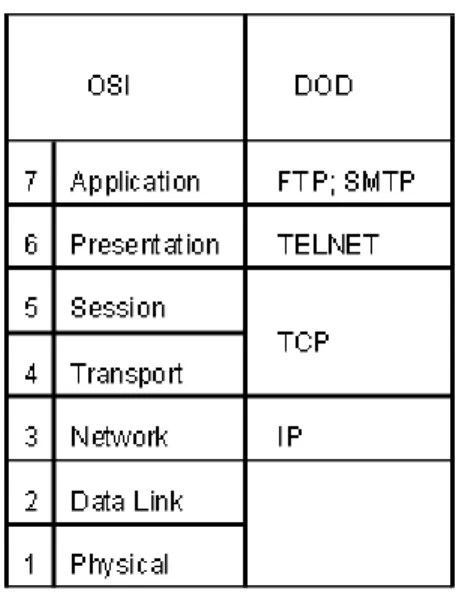
IP is the lower part of the protocol stack that makes up TCP/IP—the protocol that grew out of the Department of Defense ARPANET to become the de facto standard for movement of data on the Internet.1 In the context of the OSI model, IP is a layer 3 protocol. It depends on layers 1 and 2 for services that complete the task of moving information from one point to another. For example, our network could be a fiber-optic network using SONET transport to move ATM cells. The packets defined by IP at level 3 would then be repackaged into ATM cells defined at layers 1 and 2, over the physical fiber-optic media using SONET transport that is defined at layer 1.2
1 IMPORTANT DEFINITION: Internet (with the capital I, sometimes called the public Internet) refers to the collection of data networks accessible by the general public via an Internet Service
Provider, while internet (with a lower case I) is a generic term that refers to a wide area network which is administered by a private party, and is generally a controlled access network.
2 The functions of the various protocol layers are discussed in DigiPoints Volume One, Chapter 7. To provide another analogy, you might think of new automobiles being transported from the factory by rail. One way to do this is to load the cars onto small truck trailers holding six cars each, and then load the trailers onto rail cars. The railroad represents layer 1, the trailers represent layer 2, and the railroad cars represent layer 3.
Figure 11-1: TCP/IP Compared to the OSI Protocol Stack
IP uses the concepts of lifetime, segmentation, routing, and addressing to move packets across a network.3
• Lifetime: Each data unit traveling across the Internet has a time to live, which is typically given in 500 msec. intervals or the number of times a packet is moved between nodes in the network (hops). The total number of intervals in the time to live is set by the
originating network, and is decremented by each entity that processes the packet. If the time to live reaches zero before the packet reaches its destination, the packet is discarded. • Segmentation: Individual networks may have large size packets that cannot be
accommodated at one time by other networks. IP, therefore, segments these packets into smaller packets, tracks them, and reassembles them at their destination.4
• Routing: Layer 3 protocols also determine the routes taken through a network. Under the Internet Protocol, routing decisions are made by gateways to other networks. In the data world, these gateways are called routers. IP telephony has its own gateways, which we will discuss later.
• Addressing: IP provides a standard Internet address, which uniquely identifies computers on networks within the Internet. At the present time, a 32-bit addressing scheme is being used. These 32-bit addresses are usually represented as four decimal numbers ranging from 0 to 255, separated by dots. For example, 254.253.5.102 would be an Internet
3 In this chapter, we will refer to the data units being moved across the network as packets rather than the generic term “protocol data unit,” since layer 3 protocol data units are, by definition, packets.
4 The TCP protocol can also segment data units, within its own protocol layer, apart from the segmentation performed by the IP.
address. Each of the four decimal numbers corresponds to one group of eight bits; hence, the four groups of numbers together form a 32-bit address. Although the initial designers of IP believed that 32 bits was more than adequate for addressing all computers on their internet, the current commercialization of the Internet has taxed the addressing capacity. Therefore, a special working group of the Internet Engineering Task Force has
recommended a 128-bit addressing scheme as part of IPng (IP Next Generation) or IPv6. Each of these concepts can affect the quality of voice transmission as a telephone conversation is transported over the Internet. To see why this is the case, we next need to look at voice
packetization as it applies to IP telephony, and how it is different from the analog-to-digital conversion process that is used in circuit switched telephony.
Voice Packetization
Voice is an analog signal. Data protocols like IP transport information as a binary bit stream. Since binary bit streams are digital signals, before voice can be sent over an IP telephony network, it must first be converted into a digital format. The two methods of doing this are waveform coding and vocoding.
Waveform coding has been used in switched telephony applications since the earliest
introduction of digital multiplexing in the mid-1960s. It is a relatively straightforward technique that converts time-based samples of speech waveforms into groups of eight binary digits.
Vocoding, on the other hand, is a relatively new technology, which creates a different type of digital bit stream from models of the frequencies found in speech.
Both methods of converting an analog voice signal to a digital bit stream involve the three steps of sampling, quantizing, and encoding the signal. For IP telephony to work, the voice signal must also be compressed and packetized. We will explain each of these steps.
Sampling
A mathematical proof in communications theory called the Nyquist Theorem states that the entire information content of a signal is preserved if the signal is sampled at twice the rate of its highest frequency component. For voice over a telephone network, filters limit the upper value of frequencies to just under 4,000 Hertz. The voice telephony signal must, therefore, be sampled at 8,000 times per second to preserve its quality.
Quantizing
Quantizing takes the sample value and assigns it to a parameter that most closely describes it. The way this is done depends on whether waveform coding or vocoding is being used.
With waveform coding, the magnitude (voltage level) of the PCM sample is assigned to the closest integral value of the encoding scale. Thus, a sample value of 99.5 units may be assigned a quantum value of 100.
Quantizing for vocoding is a more complex process. Samples are grouped into frames of data, and a mathematical process called Discrete Fourier Transform is used to change the samples from their representation as a signal magnitude at a particular time into a corresponding representation as a set of frequencies. Parameters describing the frequency representation are derived, and these parameters are then quantized.
Encoding
Encoding is the process that creates the digital bit stream that represents the signal. In systems that use waveform encoding, once again, this is a straightforward process that changes the decimal value of the quantum to its binary equivalent. In systems that use vocoding, encoding includes determining the order in which the parameters are transmitted in the bit stream. In literature on vocoding systems, encoding is often the term used to describe everything that happens to the signal after it has been sampled in order to create a digital bit stream, including any quantization.
Compression
Without compression, the required bandwidth of a digitized voice signal is 8,000 x 8 bits per second, or 64 Kbps. Circuit switched telephony, using time division multiplexing, has the capacity to process and transport voice at this rate because of dedicated paths through the public switched telephone network. Because packet switched telephony is designed to share the
physical connections, voice packet calls with this bandwidth would rapidly consume existing network resources (total bandwidth of the physical connections between data nodes).
Compression increases the number of voice conversations that can be carried by a packet network at a given data rate.
Compression is not limited to packet switched networks. The telephone industry has used a type of compression known as Adaptive Differential Pulse Code Modulation (ADPCM) in toll networks within the Public Switched Telephone Network for a number of years. ADPCM, also known as ITU G.724, codes only the difference in samples, and uses a four bit-coding scheme. The result is a 32 Kbps bandwidth requirement per voice call—still high for IP telephony. ITU standard G.729 is an improved compression method known as Conjugated Structured Algebraic Code Excited Linear Predictive (CS-ACELP). This method of compression operates on “talk spurts,” or segments of speech 25 to 35 milliseconds long, to create a digital signal that accurately represents voice pitch as well as amplitude. The resulting digital voice signal occupies only 8 Kbps of bandwidth.5
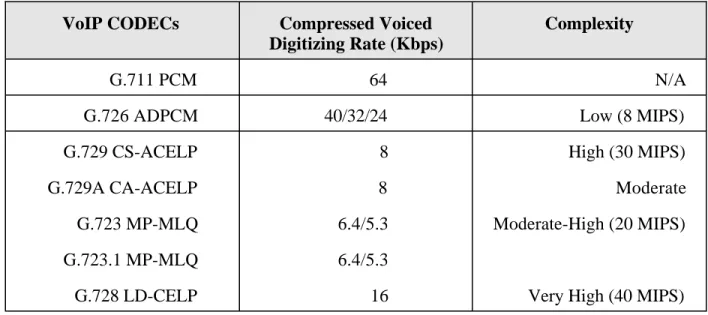
There are other standards for compression, which may also be used for signal compression. Table 11-1 is a summary of some of those standards compared to G.729.
5 In some ways, CS-ACELP is similar to JPEG video compression. Like JPEG, CS-ACELP operates in the frequency domain to compress information.
VoIP CODECs Compressed Voiced Digitizing Rate (Kbps)
Complexity
G.711 PCM 64 N/A
G.726 ADPCM 40/32/24 Low (8 MIPS)
G.729 CS-ACELP 8 High (30 MIPS)
G.729A CA-ACELP 8 Moderate
G.723 MP-MLQ 6.4/5.3 Moderate-High (20 MIPS)
G.723.1 MP-MLQ 6.4/5.3
G.728 LD-CELP 16 Very High (40 MIPS)
Table 11-1: Compression Standards
Before we leave the subject of compression, note that silence suppression, as well as the coding of intelligible speech, is an important part of compression. Studies have shown that a speech conversation is silent in either direction about 60 percent of the time. Pauses between words and sentences add another 10 percent. PCM coding without compression uses bandwidth to represent these periods of silence (essentially a run of zeros). More advanced schemes diminish the silent intervals.6
The silent intervals cannot be entirely deleted because human beings have become accustomed to hearing background noise, even during silent periods. If there is no noise, many people make the assumption that the circuit is open or the receiver is defective. Accordingly, compression
technology will either add some “white noise” or a sample of background noise to simulate ambient noise.
Packetizing
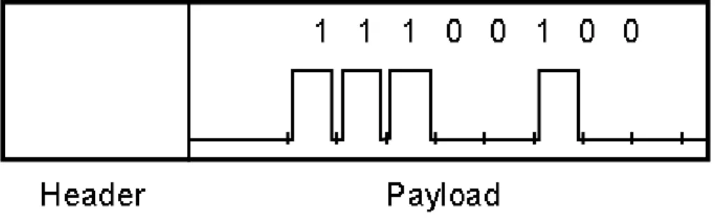
Packetizing is the grouping of the bits within the binary bit stream into data units consisting of a payload section and a header. Packets operate at the third layer of the OSI protocol reference model to route information across a data network. The header contains useful overhead
information, such as originating and terminating addresses, routing priorities, and error detection mechanisms. The payload section contains the encoded voice information.
Packet size is one factor that affects the number of calls that an IP network can carry. For a typical CODEC using G.729 compression, the voice information in a 35-millisecond “talk spurt” requires 40 bytes.7 This is only the payload part of the packet.
Figure 11-2: Packetization
Only 8 Kbps of bandwidth is required to transport these 40 bytes. (40 bytes are 40 samples in a T1 signal. There are a total of 8,000 samples per second in T1. 40/8,000 x 1,540,000 bits per second = 7.7 Kbps.) Headers must be added to the voice information for control and routing. The corresponding length of header for the 40 byte, 35 msec. “talk spurt” in our example is 28 bytes for the IP/UDP protocol overhead, and 6 bytes for the voice payload overhead, for a total header overhead of 34 bytes. This overhead adds about 7 Kbps to the 8 Kbps voice payload, resulting in a total bandwidth of 15 Kbps.
Figure 11-3: IP/UDP Voice Packet
These voice packets are the data units that carry a voice conversation through the Internet. Like all packets, they are routed independently of each other. Because of this, individual packets may experience different delays as they move across a network, or may be dropped entirely. Dropped or delayed packets can adversely affect the quality of a voice call. The public Internet is more susceptible to delays or dropped packets than a managed, private network.
7 It should be noticed that IP packets are not restricted to 40 bytes, and can be considerably longer. The length of this packet was chosen to correspond to the number of bytes needed to represent a typical talk spurt.
At the origin of the call, voice packets are sent over an 802.3 LAN, where the MAC layer protocol determines how contention with other packets on the LAN will be handled. With a MAC layer protocol that does not guarantee some priority, packets can be delayed at the source when there is heavy traffic on the LAN.
Technical Issues Surrounding IP Telephony
Human speech is, as we mentioned earlier, analog. That means we expect a continuous stream of information to reach our ears. Digital technology, and packet technology in particular, consists of bursts of data which are not continuous. In routing, the individual data packets that make up a conversation can take different paths through a network, or can be delayed by different time intervals as they travel from one point to another. They can also be corrupted or entirely lost. When any of these things happen, the digital-to-analog conversion that occurs before our ears receive the information becomes corrupted, and the result is our perception of a poor-quality voice connection.
The technical term for packet delay through the network is latency. Latency has a number of causes. It is usually caused by high traffic on one or more of the networks that comprise the internet. Consider that once both data and voice move as packets on the same network, both will contribute to the total traffic. This means that ensuring latency does not exceed acceptable levels will require managing both data and voice traffic.
Network managers must be sure adequate network nodes and paths are available during high traffic periods, possibly implying the need for more investment in network hardware as traffic grows. For telephony grade voice transmission, the maximum end-to-end latency is about 200 msec. before a subscriber will notice degradation. This includes the delays in the packet network, and any delays introduced by transmission within the Public Switched Telephone Network. Delays can also be caused by excessive errors in packet transmission. A common method of error correction is to ask for a retransmission. This can cause a double problem. In addition to the retransmitted packet arriving later than the original, more packets have been added to the
network, potentially contributing to even more delay. Once again, network management is important. It may be better to drop packets than to ask for a retransmission.
The amount of lost information that can be tolerated in a voice call is usually stated as 10 percent lost packets. Some cases have been noted where even a 25 percent loss is not noticed by the human receiving the data.8
8 We will not speculate if the “acceptable” 25 percent loss was in a conversation conducted between husband and wife, nor will we try to guess which 25 percent was lost!
One solution to excessive latency is to ensure a minimum Quality of Service (QoS) for voice packets. This means that any voice packet is guaranteed to be transmitted across the internet within the maximum time specified by its QoS. To implement a minimum guaranteed QoS
requires a network technology that supports the QoS from end to end. This problem is the subject of much discussion in both the standards bodies and the vendor community, and the complexity of the solution differs between the Internet (with the capital I) and its smaller internet
counterparts.
Internet vs. Intranet
Structure of the Internet
Because the issues we just discussed are so intimately tied to the structure of the network that transports IP telephony, it is necessary to understand how the various “internets” are constructed, and how they differ from each other. A good starting point is to look at the Internet. The Internet (with the capital I) is a hierarchical network, consisting of Internet Service Providers, regional networks and a backbone network.
End users access the Internet through a connection to an Internet Service Provider (ISP). The ISP, in turn, maintains a point of presence on the Internet, which physically is a connection from a server at the ISP to the regional network serving the ISP.
ISPs provide other services for their clients, such as hosting a domain name and building a Web site, but these services are separate from what is required for IP telephony. Within a region, there are several ISPs that can be used by subscribers to access the Internet. In some cases, a cable operator offering high-speed data services will be the ISP for its data customers.
ISPs pay a fee to access the regional network that serves them. Regional networks are private networks that connect to the national Internet backbone at national network access points (NAPs). These regional networks consist of interconnected servers (routers), which manage the movement of packets through their networks. The networks are geographically based. Examples are MIDnet providing service to the Midwestern United States, and PSCNET servicing the Eastern United States.
Which protocols are used for the logical connections between network nodes, and the degree that the regional network can offer services such as QoS, depends on the underlying technology of the network. Frame relay is a typical network protocol used by regional networks, although ATM is gaining acceptance. The physical wiring of the connections consists of high-speed data lines, either owned by the regional network, or leased from the carrier. The regional networks pay a fee to access the national backbone.
The national backbone of the Internet links the regional networks, and provides connection to networks in other countries via gateways. Like the regional network, the national network is a collection of routers and high-speed data lines. Typically, this backbone operates at higher speeds than the regional network, and uses ATM as the transport protocol. At one time, there
were four Network Access Points where the regional networks connected to the national backbone. This number is increasing as more companies get into the backbone business. Major companies which support or have supported the national backbone in the past include ANS (part of WorldComm), AT&T Network Services, BBN Planet, MCI, Sprintlink, and UUNET.9 Because there are so many participants in the Internet, packets can be delivered to locations around the world. The drawback is that there is no one entity that manages the Internet as a whole, making it difficult to guarantee packets will arrive within given time periods, or
experience a given maximum delay as they travel the Internet. In addition, the Internet is an open system. Without restrictions on access, there is no data security. To solve this problem, private organizations began creating smaller, private versions of the Internet called intranets.
Intranets and Extranets
An Intranet is owned and managed by one party, usually a corporation or organization. Access is limited to authorized users who are company employees. These users can either be permanently connected or may dial into the intranet. Although an intranet can be connected to the Internet, outside access to points on the intranet, and access to the Internet by users on the intranet, is restricted by special servers called “firewalls.” The fact that an intranet is controlled and managed by a central organization makes it a “managed” internet.
Extranets are similar to intranets, but can be accessed by a wider community of interest, such as a manufacturer, his customers, and his suppliers. Like intranets, extranets are managed internets. Because intranets and extranets are managed internets, it is easier to provide Quality of Service guarantees. Packets can be delivered between points on these internets with guaranteed
maximum delays. This makes it easier to offer IP telephony services over intranets and extranets. PacketCable™ is CableLabs’ effort to specify a managed internet operated by cable
telecommunications service providers.
IP Telephony vs. VoIP
The technology we have described up to this point is Voice over IP (VoIP), and not Internet Telephony. VoIP is essentially an alternate way to transport voice information using a data network rather than the Public Switched Telephone Network, but it does not include a standard way to connect with subscribers of the Public Switched Telephone Network. It also does not guarantee the quality of the voice transmission, nor does it provide a means to deliver features
9 Because of the merger and acquisition activity in telecommunications, it is difficult to provide a stable current list of companies. Note, however, that these examples can be recognized as large, national communications carriers.
that telephony subscribers have come to expect. These features, such as call waiting and calling number identification, are provided in circuit switched telephony by a telephony switch.
Standards for Internet Telephony address these issues. As various standards evolved, the authors of those standards first solved the problem of connecting a VoIP call to the PSTN, using
gateways. Next generations of standards specified how to improve the quality of transmission to where it virtually matches that of a call using circuit switched technology. Finally, the standards began to address how to provide telephony feature capabilities as well as simple voice transport. The next few sections of this issue trace the evolution of these standards by summarizing what is specified in two dominant specifications. H.323 began the IP telephony standards process, and is still in widespread use. The NCS 1.0 specification from the PacketCable™ initiative includes much of the work done in previous standards activities. It and the other PacketCable™ specifications are the guidelines for the cable industry to provide IP telephony that rivals the quality of circuit switched telephony.
Standards
Logical vs. Physical Components in Standards
As standards for packet telephony evolved, it became common for the authors of those standards to specify functions in terms of building blocks called logical components. Each logical
component performs a given set of functions, and the system as a whole performs as the sum of the interconnected logical components. Vendors are free to implement the logical functions in whatever hardware and software configuration they choose, and physical implementations of logical blocks are often spread across several pieces of hardware or software. Unfortunately, the names of some of the logical components are the same as hardware used in early and current vendor implementations, and there is not always a one-to-one correlation.
The H.323 gatekeeper, which will be discussed in the next section, is a good example. The translation from IP address to telephone number, although an H.323 logical gatekeeper function, is often resident in a piece of hardware called a gateway.
H.323: The ITU Takes a First Step Toward Packet Voice
Standardization
H.323 is one of the earliest standards for VoIP. It provides a specification for transport of voice packets and interconnection with the Public Switched Telephone Network. The control body for H.323 is the International Telecommunications Union (ITU), an international organization that traditionally develops specifications for telecommunications networks.
H.323 began as the specification of the technical requirements for audio and video
such, it provided a way to implement VoIP, but did not sufficiently specify telephony for local service, which requires both guarantees on Quality of Service and an extensive subscriber feature set. Its specifications, however, have been useful as the basis for packet telephony transport over private and public data networks. Thus, a major application of H.323 has been to supplement circuit-switched transport in the intercity networks of Interexchange Carriers and large private companies.10
H.323 was first approved by ITU in 1996. As more people became interested in carrying voice traffic on networks beyond LANs, a second version was issued in January 1998 to include basic telephone users being provided access to voice services over the Internet. H.323 is part of a larger set of standards that specify videoconferencing implementations for ISDN and PSTN networks, as well as LANs. Multimedia capabilities of H.323 are an important part of the standard, because they are the mechanism by which different types of terminals can
communicate with each other. However, we will concentrate on the audio specifications, which are pertinent to IP telephony.
Three “channels,” or logical paths through the network, are associated with audio information flows under H.323: a control channel, a call signaling channel, and the audio channel. The control channel is used to set up and close logical paths through a network for the audio information, and to pass general information about how data is to get through the network. An example is data flow control to avoid network congestion. The call signaling channel is used to establish a connection between two terminals on the network, using a protocol known as Q.931. This same protocol is used for ISDN call setup. The audio channel is the conduit for the voice packets.
The audio channel uses a form of IP called unreliable transmission. This is not as bad as it sounds. In the IP world, unreliable transmission is a technical term meaning a connectionless service that provides “best effort” delivery of data, without guarantees of sequencing, error control, or flow control. These tasks are not ignored. Rather, they are left to protocol layers other than the IP layer. The advantage of unreliable transmission is less overall transmission delay and increased network throughput. Because the information on the signaling and control channels is required for the audio channel to function, these channels use reliable transmission. The specific type of IP packet used for unreliable transmission is called a User Datagram Protocol packet, or UDP packet. The header length discussed earlier for an IP voice packet is the more efficient UDP header.
10Subsequent versions of H.323 begin to address basic feature capability and improved Quality of Service delivery. In general, however, other standards provide more robust solutions, with less complex hardware at the endpoints of the network.
H.323 specifies four components, or building blocks, for a network that carries IP telephony traffic:
• Terminals • Gateways • Gatekeepers
• Multipoint Control Units (MCUs)
H.323 provides the functional guidelines for vendors building these four logical components, without specifying exactly the hardware and software implementations. Like all good standards, this allows vendor creativity and gives the service provider a choice of vendors, while preserving the ability for separate vendor implementations to communicate with each other in a network.
Terminals
Terminals are the endpoints of the network. Because the word terminal is often used to describe a hardware device, the reader is reminded that in H.323 and other VoIP protocols, a terminal is a logical entity, not necessarily one type of hardware. Terminals may be associated with hardware, such as a PC, a telephone set, or a hardware gateway, but the major parameters of terminals are implemented in software.
H.323 specifies the modes of operation for different audio, video, and/or data terminals to work together. H.323 terminals must support the H.245 standard, which is used to negotiate channel usage and capabilities. In addition, they must work with Q.931 signaling and call setup, the Registration/Admission/Status (RAS) protocol to communicate with a gatekeeper, and RTP/RTCP for sequencing audio and video packets.
H.323 specifies a collection of required audio codecs, which perform the necessary
analog-to-digital conversions needed to create voice packets. Because the standard was created for multimedia applications beyond voice telephony, the terminal specification also includes provision of optional video codecs.11
Gateways
Gateways are one of the key components needed to deliver IP telephony. (Others, not part of H.323, include a telephony feature server and a managed internet.) A gateway is the bridge between the Public Switched Telephone Network and the IP network forming an internet. Gateways perform the following basic functions:
• Connection. The originating gateway is responsible for establishing the call connection, including all call setup signaling and negotiation.
11Here again, remember that the word Codec in the H.323 standard refers to a logical component. Physical pieces of hardware and/or software code, also known as codecs, implement the function of a logical codec.
• Protocol conversions between different types of terminals attached to the H.323 network. This may include demodulation and remodulation, and decompression and compression, as needed. For example, conversions may be done between packet voice and fax calls. Although both use digital formats, the formats are different. Another example is the conversion required between ISDN and POTS telephony.
These logical gateway functions are implemented in physical hardware and software. Typical hardware components are:
• Switched Circuit Network (SCN) interfaces. These are usually line interface circuit cards.
• Digital Signal Processors (DSPs). These are the brains of a gateway. DSPs are powerful processors, Pentium or better, which provide the ability to rapidly perform the functions listed above. DSPs must also implement certain voice telephony functions, like echo cancellation, that are needed to preserve call quality. Processing power is critical to a gateway, and is measured in Million Instructions per Second (MIPS). 40 MIPS DSPs are typical.
• Network Interfaces. These are the interfaces with the H.323 network, and are normally 10/100BaseT Ethernet NIC cards.
• Control Processor. This processor coordinates all the other gateway component activities. Gateway software components include the H.323 protocol stack implementation, toolkit
functions such as translation and compression algorithms, and applications software for custom features, management, and control.
Architecturally, the physical implementation of a gateway can be connected to either the access line side or the trunk side of a telecommunications switch. It could be co-located with that switch or reside at a remote location, perhaps at a cable telecommunications company headend.
Gatekeepers
Although gatekeepers are optional under the H.323 standard, they are needed for connectivity to the Public Switched Telephone Network. When present, gatekeepers assist gateways in
processing call information, and terminals are required to use the services they provide. Gatekeepers provide:
• Address translation. This is a key function for IP telephony. The gatekeeper is
responsible for address translations required for communi- cations in an H.323 network. It is the logical entity that translates an internet address to a telephone number on the
PSTN12. Other address translations that may be necessary are conversions from Local Area Network aliases (addresses which are specific to a LAN only) to internet addresses.
12The literature of H.323 often refers to this function as E.164 address translation. An E.164 address is a PSTN telephone number.
• Admissions Control. The gatekeeper processes messages that indicate whether a caller is authorized to use the network.
• Bandwidth Control. The gatekeeper must process messages from terminals requesting specific amounts of bandwidth. This function operates together with the associated bandwidth management function.
• Zone Management. Terminals are assigned to gatekeepers within specific zones. The gatekeeper must provide the above three functions to all terminals in its zone.
In addition, a gatekeeper may provide certain optional functions as follows:
• Call Control Signaling. The gatekeeper may optionally off load this function from other H.323 components.
• Call Authorization. The gatekeeper can authorize or reject calls based on criteria such as time of day, type of service, or lack of available bandwidth.
• Bandwidth Management. The gatekeeper can reserve a predetermined amount of bandwidth for functions such as e-mail. This bandwidth would not be available to other applications such as voice calls.
• Call Management. The gatekeeper may route calls to alternate terminals for predetermined conditions, such as terminal busy.
Multipoint Control Units
Multipoint Control Units (MCUs) provide the capability to have conference calls between three or more endpoint terminals. Under H.323, an MCU consists of a Multipoint Controller, which is required, and zero or more Multipoint Processors.
The Alphabet Soup of Telephony Feature Delivery
Both standards bodies and vendors realized that H.323 is not a complete specification for local telephony service. Although it provides a model for call signaling and the associated call routing, it essentially assumes a complex device at the endpoints of a call to implement the terminal functions. This line of thinking comes from its origins as a specification for local area networks, which typically connect data terminals, such as personal computers. Cable telephony, in
particular, needs to deploy a simple, inexpensive device at network endpoints. In addition, H.323 does not easily accommodate a way to rapidly deploy new features to its endpoints. Finally, by its very definition, H.323 was created to specify communications in networks with no guarantee of quality of service, which is a necessary attribute of carrier-grade telephony service.
A number of standards and specifications emerged to address these deficiencies. Because the cable industry-specific elements of these standards have been included in the PacketCable™ specifications, they will not be covered separately. For purposes of background to
• The Session Initiation Protocol (SIP) is a protocol specified by the Internet Engineering Task Force (IETF), that provides an alternate call control process to H.323. It specifies user agents and network servers, rather than terminals, gateways, and gatekeepers. Those who have studied both protocols in detail indicate that SIP is more flexible and makes it easier to implement new features.13
• The Simple Gateway Control Protocol (SGCP), and the Media Gateway Control Protocol (MGCP) are vendor contributions to standards. SGCP was developed by Cisco and Bellcore (now Telcordia) working together, and MGCP is a hybrid of SGCP and the Internet Protocol Device Control (IPDC). Call agents defined within MGCP make it easier to build simple endpoints. Both the ITU and the IETF are working together on a joint standard called H.gcp, which will include parts of SCGP, MGCP, and IPDC.
• The Distributed Open Signaling Architecture (DOSA) was developed by AT&T as a reference architecture for IP telephony. It is an enhanced version of SIP that includes network-distributed call signaling and a close matching of IP telephony call signaling with backbone Quality of Service resource allocation. It also provides for intelligent endpoints, which can implement more sophisticated terminal functions, as required.
PacketCable™
In the cable telecommunications industry, CableLabs’ PacketCable™ specifications, which build on DOCSIS 1.1, specify how various parts of an IP telephony network will communicate with each other. PacketCable™ goes beyond IP telephony to build a platform for services that require Quality of Service (QoS) guarantees. IP telephony is the first such service.
The PacketCable™ subcommittees have drawn from a variety of protocols that are being developed to address various elements of an end-to-end architecture for IP telephony. Some of the protocols that were studied include H.323, Session Initiation Protocol (SIP), Simple Gateway Control Protocol (SGCP), Internet Protocol for Device Control (IPDC), and Media Gateway Control Protocol (MGCP). Although H.323 is the most widely deployed of these protocols, CableLabs has decided that its complexity and scope are exceed what is needed in the cable telecommunications industry, and could hinder rapid vendor implementations. The
PacketCable™ architecture therefore heavily borrows from other standards, but supports interconnection with H.323 networks.
Because of the very large scope of PacketCable™, this issue will only discuss the specification for Network Call Signaling (NCS 1.0) in detail. We will define terminology from other parts of PacketCable™ as required to clarify how PacketCable™ overcomes the shortcomings of H.323 in feature delivery and QoS.
13A paper by Ismail Dalgic and Hanlin Fang, titled Comparison of H.323 and SIP for IP Telephony Signaling, is an excellent analysis. This paper was published on the Internet at
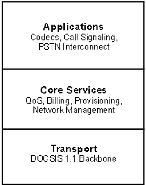
Figure 11-4: PacketCable Layers
PacketCable™ is a three-layer protocol stack. The lowest layer is the DOCSIS 1.1 local access network connected to a managed private IP backbone. It provides the transport mechanisms for IP telephony. The second layer is for core services, including security, Quality of Service, billing, network management, and provisioning. These services support the third layer, which provides for real time applications, including IP telephony. The applications layer is where codecs, call signaling, and PSTN interconnection are specified. CableLabs is specifying three codecs: G.711, G.726, and G.729. Call signaling is specified as either network-based or distributed. The network-based approach is built from the MGCP protocol and is called the Network-based Call Signaling Protocol (NCS 1.0). The distributed approach is based on the SIP protocol, and is known as the Distributed Call Signaling model.
To understand the differences between H.323 and PacketCable™, it is helpful to first review NCS 1.0 describing PacketCable’s specification of MGCP. This was the first published PacketCable™ specification, and forms a base specification for many of the others. Later specifications cover operations systems, quality of service, security, and provisioning.
NCS MGCP Components
NCS 1.0 defines four major components in an IP telephony system: • Endpoints,
• Gateways,
• Embedded clients, and • Call agents.
Endpoints are sources, or sinks, of data and could be physical or virtual. An example of a physical endpoint is an interface that terminates an analog POTS connection to a phone, key system, or PBX. An example of a virtual endpoint is an audio source in an audio-content server.
Creation of physical endpoints requires hardware installation, while creation of virtual endpoints can be accomplished by software. However, the NCS profile of MGCP only addresses physical endpoints.14
Connections are point-to-point. A point-to-point connection is an association between two
endpoints with the purpose of transmitting data between these endpoints. Once this association is established for both endpoints, data transfer between these endpoints can take place.
A gateway contains a collection of endpoints. A gateway that terminates residential POTS lines (to phones) is called a residential gateway or an embedded client.15 Gateways are also known as Media Gateways.
An embedded client is a network element that provides:
• Two or more traditional analog (RJ-11) access lines to a voice-over-IP (VoIP) network. • Optionally, one or more video lines to a VoIP network.
Embedded clients may not be confined to residential use only. For example, they may be used in a business as well. Embedded clients are used for line-side access and, as such, are expected to have line-side equipment (e.g., analog access lines for conventional telephones) associated with them, as opposed to trunks. Embedded clients may optionally support video as well.
Call Agents instruct the gateways to create connections between endpoints, to detect certain events (e.g., off-hook), and to generate certain signals (e.g., ringing). It is strictly up to the Call Agent to specify how and when connections are made, between which endpoints they are made, as well as what events and signals are to be detected and generated on the endpoints. Call agents may be distributed over multiple computer platforms (e.g., servers) within the network. A feature server is an example of such a server.
The gateway, in particular the residential gateway, thereby becomes a simple device that receives general instructions from the Call Agent without any need to worry about or even understand the concept of calls, call states, features, or feature interactions. When new services are introduced or customer profiles changed, the changes are transparent to the gateway. Call Agents implement the changes and generate the appropriate new mix of instructions to the gateways for the changes made. Whenever the gateway reboots, it will come up in a clean state and simply carry out the Call Agent’s instructions as they are received.
14CableLabs specification PKT-SP-PQOS-D01-960409 defines a voice endpoint as a Media Terminal Adapter (MTA). Specifically, an MTA is “a customer owned component that accepts analog voice input and generates IP packets using the RTP protocol.”
15PacketCable specifies another type of gateway called a trunking gateway, which is part of the PSTN gateway specification. Translation of Internet address to PSTN phone number is done at the PSTN gateway.
MGCP sends messages using User Datagram Protocol (UDP). As discussed earlier, UDP provides a type of transmission known as unreliable transmission. NCS provides for a retransmission strategy, which not only helps to recover lost packet information, but also improves network performance.
PacketCable™ Quality of Service
PacketCable™ bases its Quality of Service delivery upon DOCSIS 1.1. That specification provides for a Dynamic Quality of Service, whereby call agents per NCS 1.0 or MTAs at intelligent endpoints, per the distributed call signaling model, may request resource reservation on a per flow basis up to the Cable Modem Termination System. This allows priority treatment to be given to voice telephony packets within the PacketCable™ network. QoS between the CMTS and the backbone network is not defined by the PacketCable™ QoS specification. It is assumed that the backbone is a managed network using RSVP, or similar method, to ensure QoS.
VoIP and IP Telephony Architectures
Even as standards for IP telephony are evolving, so too are the hardware and software
architectures that are the implementations of those standards. In this section, we will examine six architectures for moving packetized voice over a network. The order of the architectures
somewhat corresponds to the historical order in which these architectures have been introduced to the field. Because the complexity of the standards increased over time, the order also goes from simple to sophisticated.
VoIP with Computer as Terminal
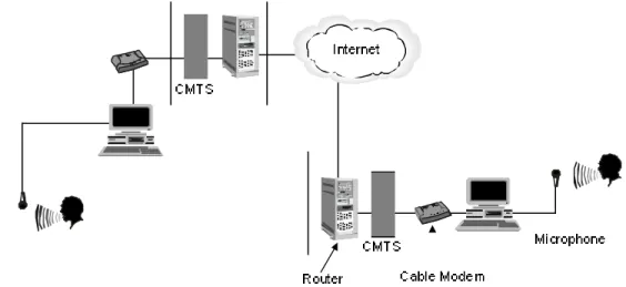
Figure 11-5 is the earliest version of IP telephony, and could easily be implemented in a cable system. The computer is equipped with software that makes it the IP telephony terminal. The analog interface to the human being is via a microphone and headset. Interface cards in the PC perform analog-to-digital conversion and compression, and the output to the cable modem is a digital data stream. At the headend, the cable modem termination system routes the call to the Internet. Destination address information embedded in the voice packets is used by the switches in the Internet to route the call to a distant computer, which is also connected, to the Internet.
Figure 11-5: VoIP Using a Computer as the Terminal
Note that in this simple architecture, no gateway to the Public Switched Telephone Network is included. It is necessary for the computers on both ends to be connected to the Internet, with an assigned address,16 before a “call” could be completed. The calling party needed to input the destination internet address as part of the call setup.
VoIP with Gateway to PSTN
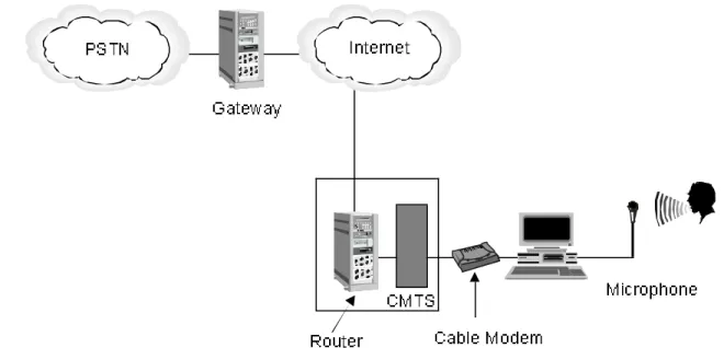
Figure 11-6 illustrates an improvement over the previous architecture in that the computer user can now complete a call to a subscriber on the Public Switched Telephone Network. The computer is equipped with software that makes it the IP telephony terminal. At the headend, a router associated with the cable modem termination system routes the call to a gateway, which initiates a connection to the PSTN. There can be several variations on how the gateway
completes a call to a PSTN subscriber, but most are fairly awkward for a caller that is not a sophisticated computer user. In many cases, the call originator needs to know a specific internet address associated with a gateway in a distant city, as well as the calling party’s PSTN phone number.
16For the example, we will not go into the details of how addresses are assigned. In most cases however, the computers would be associated with either a leased IP address viaDHCP or a private internet address known to a router, which in turn has its own public Internet address.
Figure 11-6: VoIP with a Gateway to the PSTN Using a Computer as the terminal
A variation of this architecture, however, has proven to be a useful business opportunity. An alternate service provider can maintain a network of gateways at various cities. A caller dials a telephone number from an ordinary telephone to be connected to an answering device at the gateway location. Authorization codes entered either via a phone keypad or credit card scanner tell the gateway that it can accept dialed digits from the caller, translate them to the appropriate internet address of a gateway at the location where the call could be completed as a local call via the second gateway.
The disadvantage is that gateways owned by the service provider must be at both ends of the call, and the calling party needs to first complete a call to the gateway, before completing a call to the distant location.
Traditional telephony service providers and large businesses are also using this type of
architecture to complete calls over their own managed internets. In this case, the service provider or business may also own telephony switches that automatically perform the routing to the
internet gateway, without requiring the end user to dial special telephone numbers to access the network.
VoIP with Phone Adapter (MTA)
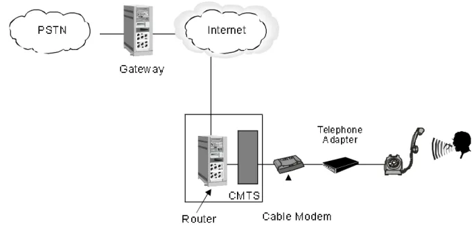
Figure 11-7 is a version of IP telephony that is very similar to Figure 11-6, except that the computer is replaced by a combination of a standard telephone set and an adapter that connects to a cable modem. In this case, the adapter performs the analog-to-digital conversion and compression, and allows the subscriber to use IP telephony in a very similar way to using standard circuit switched telephony.
Figure 11-7: VoIP with a Gateway to the PSTN Using a Phone Adapter
The advantage of this configuration over the configuration in Figure 11-6 is that the consumer can use what appears to be a standard telephone set to make a phone call. In reality, the telephone is a specially designed (and more costly) “IP telephone.”
IP Telephony with Phone Adapters or IP NIU-Access Network Only
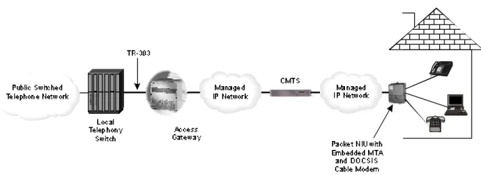
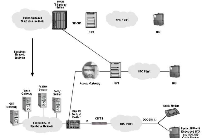
In this architecture, the MTA and cable modem are made integral parts of the NIU, so that all phones in the residence will be connected to the MTA – cable modem combination. To the customer, this connection appears to be the same as a connection to the incumbent phonecompany’s network. In order to provide a set of features that are equivalent to those provided by a standard phone connection, the service provider must either connect the customer to a
telephony circuit switch, or have an equivalent capability via a feature server attached to the network. As an interim solution prior to widespread availability of end-to-end IP telephony architecture, it is possible to connect an IP access network to a gateway that provides a standard TR-303 interface to a digital telephony circuit switch. An illustration of such an architecture is shown in Figure 11-8.
Figure 11-8: Full-Feature Telephony via IP Access to a Circuit Switch
IP Telephony – End-to-End Solution
The ultimate goal is to provide carrier grade, fully featured local telephony service without using a circuit switch. Figure 11-9 illustrates this architecture. Telephony is provided over a full
service IP backbone network, with features implemented by servers on the network. Connectivity to the PSTN is available, as required, via gateways connected to the IP backbone network.
Figure 11-10: Cable Telephony Migration
Migration From Circuit Switched Constant Bit Rate
Telephony to IP Telephony
Because telephony is a revenue generating opportunity, many operators have begun to implement circuit switched architectures to meet immediate market needs. The challenge of migrating those architectures to IP telephony is being addressed by all the vendors of circuit switched cable telephony systems. Most operators do not want to do a “forklift upgrade”
involving a total replacement of an existing system. In addition to the costs involved, this type of change forces a customer outage as the system is changed to the new architecture.
Figure 11-10 is one solution offered by Arris-Interactive, where a cable modem termination system is built into a card that can be installed in existing circuit-switched telephony Host Digital Terminals. Circuitry in the HDT routes calls from circuit switched customers to a circuit switch, and calls from IP telephony customers to a packet network.
Summary
Cable operators are moving quickly to a digital network for all their services. IP telephony is a form of digital telephony that does not need a telephony circuit switch. It is a technology that has evolved in less than three years from a hobby to a carrier grade service.
H.323 was the first major standard for packetized voice. Although it does not provide all the features and quality of service of a circuit switched solution, H.323 specifies a viable method of call signaling and voice packet transport As such, it has formed the basis for network-based VoIP as implemented by interexchange carriers and corporate enterprise networks.
Subsequent standards for packet telephony have brought the technology to the level of
carrier-grade local telephone service. Simplified endpoints have become possible with MGCP facilitating lower cost and more energy-efficient implementations. Logical call agents within an MGCP network permit subscriber features to reside on network-based servers, rather than within circuit switches.
The PacketCable™ initiative from CableLabs has built upon existing standards for packetized voice, to create the foundation for IP telephony offerings over HFC cable networks. It specifies both a network call signaling model, and a distributed call signaling model, allowing for both simple residential endpoints and sophisticated multimedia terminals needed to support business and home office applications.
Learning Just Enough to be Dangerous: Glossary
ADPCM - Adaptive Differential Pulse Code Modulation. Type of audio compression used in toll networks.
Call Agent - MGCP-specified entity that instructs gateways to create connections between endpoints.
Channel - Logically defined path through a network.
CODEC - Software or hardware that performs analog-to-digital conversion and compression. CODEC is short for Code - Decode.
CS-ACELP - Conjugated Structured Algebraic Code Excited Linear Predictive. Type of audio compression used in IP telephony that compresses voice into 8 Kbps of bandwidth.
Digital Signal Processor - Powerful processor with high MIPS (million instructions per second) rate that enables many of the functions of an IP telephony gateway.
DSP - Digital Signal Processor.
ETSI - European Telecommunications Standards Institute.
Extranet - Privately owned and managed data network open to a limited community of interest, such as manufacturers and their suppliers.
Gateway - One of the components of packet telephony defined by standards. Its major function is to interface IP networks to switched networks.
H.323 - North American standard for IP telephony.
Internet - The collection of data networks accessible by the general public via an Internet Service Provider.
internet - Controlled access, Wide Area Network which is administered by a private party.
Intranet - Privately owned data network similar to the Internet, except that access is only available to authorized parties, usually employees of the network owner. One type of internet.
IP Telephony - The transport of carrier grade voice telephony over an internet or over a combination of an internet and the Public Switched Telephone Network, using the Internet Protocol, and providing a full set of subscriber features.
ISP - Internet Service Provider.
Latency - Delay in packet delivery as it passes through a network.
MGCP - Media Gateway Control Protocol
MTA - Media Terminal Adapter
NAP - Network Access Point
Network Access Point - Point at which regional networks on the Internet connect to the national Internet backbone.
PacketCable - CableLabs initiative to define a managed internet that would be run by cable service operators.
Q.931 - Telephony signaling protocol.
QoS - Quality of Service. Includes guaranteed maximum delay that will be encountered by a packet transported across a network.
SCN - Switched Circuit Network.
Switched Circuit Network - Network that established a physical path from one party to another for the duration of a session.
Talk spurt - Unit of compressed speech.
TIPHON - Telecommunications and Internet Protocol Harmonization Over Networks.
VoIP- Packetized voice transport, without provision for subscriber features or guarantee of quality of service.
Testing Your Knowledge
1. What is the fundamental difference between IP telephony and switched-circuit telephony? 2. What are the steps in preparing a voice signal for transmission over an IP network? Which
of these steps are common to all analog-to-digital conversions?
3. What is the most common cause of poor quality transmission in an IP telephony call? Why does it happen?
4. Why is it easier to provide good quality IP telephony over an intranet than on the Internet? 5. What are the four components of IP telephony as specified by H.323?
6. What are the six main functions of an H.323 gatekeeper?
7. What are the four components of MGCP, as specified in PacketCable™ NCS 1.0? 8. Your boss says, “Telephony in a cable system is just too risky a business now. We can’t
commit to circuit switched HFC telephony with all this talk about IP telephony being the future technology for telecommunications. We need to wait until IP telephony matures before we get into the telephony business.” How would you try to convince him that there are ways to get into telephony now that may make sense?
Answers To Volume III, Issue 10 Questions
1. What is the difference between twisted pair and D-Station Wire and which is the preferred wire for installations?
D-Station wire or Quad-wire is voice grade station wiring typically found in homes. It consists of four (4) copper wires loosely held in a plastic sheath. The consumer can purchase this wire at any of several retail outlets. Twisted pair is copper wire where two wires are wrapped about each other. In basic installations, four (4) twisted pair will be found in a sheath. Twisted pair is a higher quality material than D-Station wire, and it is preferred for inside wiring installations.
2. Name and describe the two different techniques or methods used in running wire for telephones in residential buildings? Which is the preferred method? Why is it preferred?
The two methods are known as Homerun and the Loop. When using the Homerun technique, each jack is wired back to a known cross-connect point near the NID. When using the Loop method, wiring from one jack is extended to one or more other jacks. This can continue and grow in complexity at subsequent telephone jacks. The preferred method is the Homerun method. The Homerun method is preferred because it makes
troubleshooting, repair, and changes easier.
3. What does the acronym “NID” mean, and what is the purpose of this device?
The NID, or Network Interface Device (also called a Network Interface Unit), is the DEMARC (demarcation point) between the service provider’s network and the customer’s station wire. Besides providing protection and isolation of the customer’s wiring system and the network, it also provides a test point for maintenance and repair purposes. 4. What is the significance of the term “Category” as it relates to wire, and what is the recommended
“Category” to be used in today’s installations? Why?
The Category rating used for wiring indicates the bandwidth that the wire is rated to carry. The higher the category number, the higher the rated bandwidth of the wire. CAT 3 is the minimum wire that should be used in an installation. CAT 5 is the recommended wire to be used. It is recommended so that the wiring system does not become prematurely obsolete. CAT 5 can carry 10 times the bandwidth of CAT 3: 100 MHz versus 10 MHz. 5. What is a SOHO and how would it be wired differently from a normal residence? A small office in
a business park?
Small Office/Home Office is what this acronym represents. The SOHO, to be properly configured, should only have twisted pair brought to it, and that twisted pair should come to the home office using the homerun or star architecture. Also, in or near the home office, a simple patch panel should be installed to permit quick and easy reconfiguration of the equipment in the room. A small office in a business park, e.g., 3-7 employees, would be installed along the same principles. The patch panel becomes even more important to allow the company to rearrange their offices without having to contact the service provider.
6. What might be observed if the tip and ring were reversed?
If the customer uses MF (multi-frequency) outpulsing, otherwise known as touch tone, then it will not be possible to break dial done when dialing. These will not be a problem on rotary dialed telephones.
7. What is the purpose of the tone generator? With what piece of equipment is it paired?
The tone generator, or toner, when connect to the cable pair, will output a tone to an associated probe. The tone can be detected not only at the termination point, but anywhere along the path of the cable, including through walls and other physical obstructions. The tone generator thus allows the installer to identify a pair of wires. 8. Name three ways that an installer can be responsible for causing noise on the line.
By having a loose connection or a fractured wire. The latter can be caused by pulling the wire too hard or by having too tight a turn or a kink in the wire. Noise can also occur if the wire is on or very near a heat source. Finally, noise can be induced by having the wiring near an electric motor or other device.
9. Why is it inadvisable to run telephone wire in the same conduit as power wire or to even run it in parallel with ROMEX™ type electrical wire. (NOTE: ROMEX is a type of electrical wire that some building codes permit to be used which does not have mechanical protection.)
First, signals on the electrical wire could induce a 60 hertz frequency signal onto the line. This is a very annoying noise which will be detectable on any instrument connected to that line. Second, if the physical barrier breaks down between the two conductors, the
telephone wire will have 110-120 VAC on it. This can damage equipment, and may injure the customer.