DOCSIS® Provisioning of EPON Specifications
DPoEv2.0
DPoE MAC and Upper Layer Protocols Interface
Specification
DPoE-SP-MULPIv2.0-I08-150611
ISSUED
Notice
This DPoE™ specification is the result of a cooperative effort undertaken at the direction of Cable Television Laboratories, Inc. for the benefit of the cable industry and its customers. You may download, copy, distribute, and reference the documents herein only for the purpose of developing products or services in accordance with such documents, and educational use. Except as granted by CableLabs in a separate written license agreement, no license is granted to modify the documents herein (except via the Engineering Change process), or to use, copy, modify or distribute the documents for any other purpose. This document may contain references to other documents not owned or controlled by CableLabs. Use and understanding of this document may require access to such other documents. Designing,
manufacturing, distributing, using, selling, or servicing products, or providing services, based on this document may require intellectual property licenses from third parties for technology referenced in this document. To the extent this document contains or refers to documents of third parties, you agree to abide by the terms of any licenses associated with such third party documents, including open source licenses, if any.
DISCLAIMER
This document is furnished on an "AS IS" basis and neither CableLabs nor its members provides any representation or warranty, express or implied, regarding the accuracy, completeness, noninfringement, or fitness for a particular purpose of this document, or any document referenced herein. Any use or reliance on the information or opinion in this document is at the risk of the user, and CableLabs and its members shall not be liable for any damage or injury incurred by any person arising out of the completeness, accuracy, or utility of any information or opinion contained in the document.
CableLabs reserves the right to revise this document for any reason including, but not limited to, changes in laws, regulations, or standards promulgated by various entities, technology advances, or changes in equipment design, manufacturing techniques, or operating procedures described, or referred to, herein.
This document is not to be construed to suggest that any company modify or change any of its products or procedures, nor does this document represent a commitment by CableLabs or any of its members to purchase any product whether or not it meets the characteristics described in the document. Unless granted in a separate written agreement from CableLabs, nothing contained herein shall be construed to confer any license or right to any intellectual property. This document is not to be construed as an endorsement of any product or company or as the adoption or promulgation of any guidelines, standards, or recommendations.
Document Status Sheet
Document Control Number: DPoE-SP-MULPIv2.0-I08-150611
Document Title: DPoE MAC and Upper Layer Protocols Interface Specification
Revision History: I01 - Released 10/04/12 I02 - Released 03/28/13 I03 - Released 08/08/13 I04 - Released 11/14/13 I05 - Released 03/27/14 I06 - Released 08/07/14 I07 - Released 03/19/15 I08 - Released 06/11/15 Date: June 11, 2015 Status: Work in Progress
Draft Issued Closed
Distribution Restrictions: Author Only
CL/Member CL/ Member/ Vendor
Public
Key to Document Status Codes
Work in Progress An incomplete document, designed to guide discussion and generate feedback that may include several alternative requirements for consideration.
Draft A document in specification format considered largely complete, but lacking review by Members and vendors. Drafts are susceptible to substantial change during the review process.
Issued A generally public document that has undergone Member and Technology Supplier review, cross-vendor interoperability, and is for Certification testing if applicable. Issued Specifications are subject to the Engineering Change Process. Closed A static document, reviewed, tested, validated, and closed to further engineering
change requests to the specification through CableLabs.
Trademarks
CableLabs® is a registered trademark of Cable Television Laboratories, Inc. Other CableLabs marks are listed at http://www.cablelabs.com/certqual/trademarks. All other marks are the property of their respective owners.
Contents
1 INTRODUCTION ... 11
1.1 DPoE Technology Introduction ... 11
1.2 Scope ... 11
1.3 Goals ... 12
1.4 Requirements ... 12
1.5 DPoE Version 2.0 Specifications ... 12
1.6 Reference Architecture ... 13
1.7 DPoE Interfaces and Reference Points ... 14
2 REFERENCES ... 17
2.1 Normative References... 17
2.2 Informative References ... 19
2.3 Reference Acquisition... 20
3 TERMS AND DEFINITIONS ... 21
3.1 DPoE Network Elements ... 21
3.2 Other Terms and Definitions ... 23
4 ABBREVIATIONS AND ACRONYMS ... 24
5 OVERVIEW AND THEORY OF OPERATIONS ... 27
5.1 MULPI Key Features ... 27
5.2 Technical Overview ... 27
5.2.1 Multicast Operation ... 28
5.2.2 Network and Higher Layer Protocols ... 28
5.2.3 vCM, D-ONU, and CPE Provisioning and Management ... 29
5.2.4 Relationship to the Physical Plant Topology ... 31
6 MEDIA ACCESS CONTROL SPECIFICATION ... 34
6.1 Introduction ... 34
6.1.1 Overview ... 34
6.1.2 Definitions... 35
6.2 MAC Frame Formats ... 35
6.2.1 Generic MAC Frame Format... 35
6.3 MAC Management Messages ... 36
6.3.1 DPoE OAM Messages ... 36
7 MEDIA ACCESS CONTROL PROTOCOL OPERATION ... 38
7.1 Timing and Synchronization ... 38
7.1.1 Synchronization in EPON ... 38
7.1.2 EToD, Phase and Frequency Distribution ... 39
7.1.3 Operating Principle ... 41
7.1.4 Synchronization of multiple DPoE Systems to common reference clock ... 42
7.1.5 Control and Management for EToD Distribution Service ... 42
7.1.6 1588v2 Provisioning Parameters ... 43
7.2 Upstream Data Transmission ... 43
7.2.1 Upstream Bandwidth Allocation ... 43
7.2.2 Upstream Transmission Request Policies and Contention Resolution ... 43
7.2.3 Upstream Service Flow Scheduling Services ... 43
7.3 Quality of Service ... 45
7.3.1 QoS Model in DPoE ... 45
7.3.2 Frame Classification and Rule execution ... 50
7.3.4 Service Classes ... 55
7.3.5 Authorization ... 55
7.3.6 SF and Classifiers ... 55
7.3.7 QoS Support for Downstream IP Multicast Traffic ... 57
7.3.8 IPv6 Multicast Traffic and Other Multicast ... 58
7.4 Acquiring D-ONU capabilities and D-ONU provisioning ... 58
7.5 D-ONU Capabilities ... 59
7.6 Data Link Encryption Support ... 60
7.7 Power Saving ... 60
7.7.1 General requirements ... 60
7.7.2 Specific requirements ... 60
8 DATA FORWARDING ... 61
8.1 MEF Forwarding Requirements ... 61
8.1.1 Provider Bridge (PB) ... 61
8.1.2 Provider Backbone Bridge (PBB) ... 62
8.2 Multicast Forwarding ... 63
8.2.1 Introduction ... 63
8.2.2 Downstream Multicast Forwarding ... 63
8.2.3 Downstream Multicast Encryption ... 65
8.2.4 Upstream Multicast Forwarding and Encryption ... 65
8.2.5 Static Multicast Session Encodings ... 65
8.2.6 IGMP and MLD Support ... 65
8.2.7 Explicit Tracking of CPEs Joined to a Multicast Group ... 66
8.2.8 IPv6 Multicast Traffic: Neighbor Discovery, Router Solicitation, etc. ... 66
8.3 Requirements for IP(HSD) and L2HSD Forwarding ... 66
8.3.1 IP Serving Group (IP-SG) ... 67
8.3.2 Layer 2 HSD (L2HSD) ... 67
8.4 L2VPN Layer 2 Forwarding Services ... 67
9 DPOE SYSTEM AND D-ONU INTERACTION ... 69
9.1 D-ONU and vCM Initialization and Reinitialization ... 69
9.1.1 Scan for Downstream Channel ... 69
9.1.2 Continue Downstream Scanning ... 69
9.1.3 Service Group Discovery and Initial Ranging ... 69
9.1.4 Authentication ... 69
9.1.5 Establishing IP Connectivity... 69
9.1.6 Registration with the DPoE System ... 84
9.1.7 Service IDs During vCM Initialization ... 85
9.2 Periodic Maintenance ... 85
9.3 Fault Detection and Recovery ... 86
9.3.1 MAC Layer Error-Handling ... 86
9.4 vCM and D-ONU Operational Relationship ... 87
9.5 Dynamic D-ONU Configuration Update Mechanism ... 87
9.5.1 High Level Operation ... 88
9.5.2 Dynamic Config Update Steps ... 90
9.5.3 Operational State ... 92
9.6 UNI Management ... 92
10 DOWNLOADING CABLE MODEM OPERATING SOFTWARE ... 93
ANNEX A WELL-KNOWN ADDRESSES (NORMATIVE) ... 94
ANNEX B PARAMETERS AND CONSTANTS (NORMATIVE) ... 95
ANNEX C COMMON TLV ENCODINGS (NORMATIVE) ... 96
C.1.1 [802.1ad] S-TPID ... 96 C.1.2 [802.1ad] S-VID ... 97 C.1.3 [802.1ad] S-PCP ... 97 C.1.4 [802.1ad] S-DEI ... 97 C.1.5 [802.1ad] C-TPID ... 98 C.1.6 [802.1ad] C-VID ... 98 C.1.7 [802.1ad] C-PCP ... 98 C.1.8 [802.1ad] C-CFI ... 99 C.1.9 [802.1ad] S-TCI ... 99 C.1.10 [802.1ad] C-TCI ... 99
C.2 [802.1ah] Packet Classification Encodings ... 99
C.2.1 [802.1ah] I-TPID ... 100 C.2.2 [802.1ah] I-SID ... 100 C.2.3 [802.1ah] I-TCI ... 100 C.2.4 [802.1ah] I-PCP ... 100 C.2.5 [802.1ah] I-DEI ... 101 C.2.6 [802.1ah] I-UCA ... 101 C.2.7 [802.1ah] B-TPID ... 101 C.2.8 [802.1ah] B-TCI ... 102 C.2.9 [802.1ah] B-PCP ... 102 C.2.10 [802.1ah] B-DEI ... 102 C.2.11 [802.1ah] B-VID ... 102 C.2.12 [802.1ah] B-DA ... 103 C.2.13 [802.1ah] B-SA ... 103 C.3 MPLS Classification Encodings ... 103 C.3.1 MPLS TC bits ... 103 C.3.2 MPLS Label ... 103
C.4 Ethernet LLC Packet Classification Encodings ... 104
C.4.1 Slow Protocol Subtype ... 104
C.5 Metro Ethernet Service Profile (MESP) ... 104
C.5.1 MESP Reference ... 104
C.5.2 MESP Bandwidth Profile (MESP-BP) ... 104
C.5.3 MESP Name ... 108
C.6 Aggregate Service Flow (ASF) ... 108
C.6.1 Upstream Aggregate Service Flow Encodings ... 108
C.6.2 Downstream Aggregate Service Flow Encodings ... 108
C.6.3 ASF Reference ... 108
C.6.4 MESP Reference ... 109
C.7 Changes to DOCSIS TLV 24/25... 110
C.7.1 Aggregate Service Flow Reference ... 110
C.7.2 Metro Ethernet Service Profile (MESP) Reference ... 110
C.7.3 Serving Group Name ... 110
C.7.4 SF Collection ... 110
C.8 D-ONU Capabilities Encoding ... 110
C.8.1 DPoE Version Number ... 111
C.8.2 Number of Unicast LLIDs Supported (Bidirectional) ... 111
C.8.3 Number of Multicast LLIDs Supported (Downstream Only) ... 111
C.8.4 MESP Support (Metro Ethernet Service Profile) ... 111
C.8.5 Number of D-ONU Ports ... 112
C.8.6 EPON Data Rate Support ... 112
C.8.7 Service OAM ... 112
C.9 Network Timing Profile ... 112
C.9.1 Network Timing Profile Reference ... 113
C.9.2 Network Timing Profile Name ... 113
C.10 Top Level TLVs ... 113
C.12 Security (TLV 17) ... 116
C.13 Classification (TLVs 22 and 23) ... 116
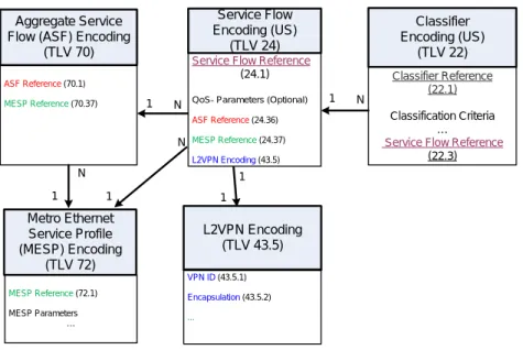
C.14 Service Flows and Aggregate (TLVs 24, 25, and 70, 71) ... 119
C.15 Device Management (TLVs 38, 53 and 54) ... 120
C.16 TLV 43 ... 121
C.17 [DPoE-MEFv2.0] and [L2VPN] (TLVs 43.5, 45, and 65) ... 122
C.18 Customer (Subscriber) Management (TLV 43.7) ... 123
C.19 Upstream Drop Classification (TLV 60) ... 123
C.20 Subscriber Management (TLV18 and TLV35) ... 125
ANNEX D ESAFE DHCP SNOOPING (NORMATIVE) ... 126
ANNEX E MPCP DISCOVERY PROCESSING IN DPOE NETWORKS ... 127
E.1 IEEE MPCP Discovery Process ... 127
E.2 DPoE MPCP Discovery Process ... 127
E.2.1 Discovery Using Multiple GATE messages ... 129
APPENDIX I EPON MEDIA ACCESS CONTROL PROTOCOL (INFORMATIVE) ... 132
I.1 Timing and Synchronization ... 132
I.1.1 MPCP Clock Synchronization ... 132
I.1.2 Loop Timing in EPON ... 132
APPENDIX II EPON MULTIPOINT CONTROL PROTOCOL DATA UNITS (INFORMATIVE) ... 133
APPENDIX III ILLUSTRATION OF SERVICE FLOW AGGREGATION (INFORMATIVE) ... 135
APPENDIX IV DPOE MULTICAST FLOW DIAGRAMS (INFORMATIVE) ... 136
APPENDIX V ACKNOWLEDGEMENTS (INFORMATIVE) ... 139
APPENDIX VI REVISION HISTORY (INFORMATIVE)... 140
VI.1 Engineering Change incorporated into DPoE-SP-MULPIv2.0-I02-130328 ... 140
VI.2 Engineering Changes incorporated into DPoE-SP-MULPIv2.0-I03-130808 ... 140
VI.3 Engineering Changes incorporated into DPoE-SP-MULPIv2.0-I04-131114 ... 140
VI.4 Engineering Changes incorporated into DPoE-SP-MULPIv2.0-I05-140327 ... 140
VI.5 Engineering Changes incorporated into DPoE-SP-MULPIv2.0-I06-140807 ... 140
VI.6 Engineering Changes incorporated into DPoE-SP-MULPIv2.0-I07-150319 ... 141
Figures
Figure 1 - DPoEv2.0 Reference Architecture ... 13
Figure 2 - DPoEv2.0 Interfaces and Reference Points ... 14
Figure 3 - D-ONU Types ... 22
Figure 4 - DPoE Network Elements ... 22
Figure 5 - D-ONU Initialization ... 29
Figure 6 - vCM within the DPoE network ... 30
Figure 7 - Graphical Representation of the EToD Distribution Mechanism in DPoE Network ... 40
Figure 8 - Illustration of Relationship for EToD Parameters ... 41
Figure 9 - Object Model Diagram for Upstream ASF and MESP TLVs and Relationship to DPoE L2VPN Model .. 46
Figure 10 - Object Model Diagram for Downstream ASF and MESP TLVs and Relationship to L2VPN Model ... 47
Figure 11 - Example of Three Upstream SFs (SF1, SF2, and SF3) Aggregated into ASF ... 47
Figure 12 - Example of Three Downstream SFs (SF1, SF2, and SF3) Aggregated into ASF ... 48
Figure 13 - 802.1ad and 802.1ah Classifiers... 54
Figure 14 - Establish IP Connectivity ... 70
Figure 15 - IPv4-only Provisioning Mode ... 71
Figure 16 - IPv6-only Provisioning Mode ... 72
Figure 17 - IPv6 Address Acquisition ... 73
Figure 18 - Establishment of IPv4 Network Connectivity ... 74
Figure 19 - Establishment of IPv6 Network Connectivity ... 78
Figure 20 - Registration of D-ONU in DPoE System ... 84
Figure 21 - BackOffice System Operation ... 89
Figure 22 - Operation of the vCM ... 90
Figure 23 - MPCP Discovery Process Message Sequence. ... 127
Figure 24 - Discovery Process with registerStartTime, registerAckDelay, and registerDeadline. ... 128
Figure 25 - DPoE MPCP Discovery Process Using Multiple Auxiliary GATE Messages, REGISTER_ACK Message Arrived in Grant from Auxiliary GATE Message. ... 130
Figure 26 - DPoE MPCP Discovery Process Using Multiple GATE Messages, REGISTER_ACK Message Arrived in Grant from Deadline GATE message. ... 131
Figure 27 - Behavior of Devices within MEF network ... 135
Figure 28 - Behavior of ASF-SF within D-ONU ... 135
Figure 29 - Dynamic Join ... 136
Figure 30 - Static ... 136
Figure 31 - Downstream Multicast Data Traffic Forwarding ... 137
Figure 32 - Downstream Multicast Control ... 137
Figure 33 - Multicast Group Specific Messages ... 138
Tables
Table 1 - DPoE 2.0 Series of Specifications ... 12
Table 2 - DPoEv2.0 Interface and Reference Point Descriptions ... 15
Table 3 - DPoE Upstream Service Flow Parameters ... 44
Table 4 - DHCPv4 Discover/Request Fields ... 76
Table 5 - DHCPv4 Response ... 77
Table 6 - DHCPv6 Solicit/Request Options ... 81
Table 7 - DHCPv6 Advertise/Confirm Fields ... 81
Table 8 - Top Level TLVs ... 113
Table 9 - TLV 11 ... 115 Table 10 - TLV 17 ... 116 Table 11 - TLV 22 and 23 ... 116 Table 12 - TLV 24, 25, and 70, 71 ... 119 Table 13 - TLV 38, 53 and 54 ... 120 Table 14 - TLV 43 ... 121 Table 15 - TLV 43.5, 45, and 65 ... 122 Table 16 - TLV 43.7 ... 123 Table 17 - TLV 60 ... 123
1 INTRODUCTION
DOCSIS Provisioning of EPON (DPoE) version 2.0 specifications are a joint effort of Cable Television Laboratories (CableLabs), cable operators, vendors, and suppliers to support EPON technology using existing DOCSIS-based back office systems and processes. DPoE v2.0 specifications augment the DPoE v1.0 specifications to provide requirements for additional service capabilities and corresponding provisioning and network management capabilities.
Ethernet PON (EPON) is an [802.3] standard for a passive optical network (PON). A PON is a specific type of multi-access optical network. A multi-access optical network is an optical fiber based network technology that permits more than two network elements to transmit and receive on the same fiber.
DPoE specifications are focused on DOCSIS-based provisioning and operations of Internet Protocol (IP) using DOCSIS Internet service (which is typically referred to as High Speed Data (HSD)), or IP(HSD) for short, and Metro Ethernet services as described by Metro Ethernet Forum (MEF) standards. DPoE Networks offer IP(HSD) services, functionally equivalent to DOCSIS networks, where the DPoE System acts like a DOCSIS CMTS and the DPoE System and DPoE Optical Network Unit (ONU) together act like a DOCSIS CM.
1.1 DPoE Technology Introduction
1DPoE technology was established with the following common requirements already developed by operators. Each of the participant operators had previously selected 1G-EPON and 10G-EPON as the appropriate technology for one or more applications. EPON is a widely deployed technology with a sufficient and large supply of vendors offering a variety of products for each component of the access network. 10G-EPON technology is available and is backwards compatible with 1G-EPON. A 1G-EPON network can be incrementally upgraded to 10G-EPON, adding or
replacing ONUs as business needs require. 1G-EPON and 10G-EPON are compatible with [SCTE 174].
1G-EPON and 10G-EPON, originally defined in [802.3ah] and [802.3av] respectively, support a point-to-multipoint architecture with a centralized controller called an Optical Line Terminal (OLT) and distributed low cost Layer 2 ONUs. The basic service mapping architecture in EPON is to map Ethernet (or IP) frame header information (e.g., addresses, IP Differentiated Service Code Points, Ethernet Q tag, S-VLAN/C-VLAN ID, ISID, bridge address, etc.) to a logical circuit called a Logical Link Identifier (LLID) in [802.3]. The service mapping function in DPoE specifications is similar to that used in DOCSIS specifications. Both DOCSIS and DPoE networks rely on a centralized scheduler though EPON utilizes an LLID which functions like a SID in DOCSIS to support unicast, broadcast, and multicast.
At the time when development efforts around the DPoE specifications started, there were no standard management interfaces for the ongoing operations and maintenance of the network, including fault management, performance management, security, etc. Operators already had fully working and scaled-out systems that solve these challenges for DOCSIS networks. One of the primary goals for DPoE specifications was therefore to use the existing DOCSIS back office infrastructure to scale up EPON-based business services.
1.2 Scope
2As the name suggests, the scope for this document is the MAC and upper layer protocols for DPoE Networks. The MAC in DPoE Networks is EPON. This specification does not place any additional requirements on the EPON MAC beyond the [802.3] specifications for EPON. The first set of requirements is for the support of DOCSIS-based Operations Administration Maintenance and Provisioning (OAMP) for the MAC and upper layer protocols as specified in [MULPIv3.0]. The second set of requirements is in addition to the above functionality traffic classification (as provisioned) and traffic forwarding (as both provisioned and according to the requirements set forth in this specification).
1
Revised per MULPIv2.0-N-14.0172-1 on 7/16/14 by JB.
2
The primary addition to the DOCSIS specifications are the requirements and accompanying specifications for Metro Ethernet services as described in [DPoE-MEFv2.0].
1.3 Goals
The objective of this specification is to document the requirements to support the automated provisioning of IP High Speed Data Services and Metro Ethernet services over EPON network using DOCSIS provisioning methods and backend servers. The intention of this document is to specify requirements and guidelines to assure interoperability between DPoE products. The idea is to establish requirements that are in addition and in some cases in replacement of requirements in DOCSIS 3.0.
1.4 Requirements
Throughout this document, the words that are used to define the significance of particular requirements are capitalized. These words are:
"MUST" This word means that the item is an absolute requirement of this specification. "MUST NOT" This phrase means that the item is an absolute prohibition of this specification.
"SHOULD" This word means that there may exist valid reasons in particular circumstances to ignore this item, but the full implications should be understood and the case carefully weighed before choosing a different course.
"SHOULD NOT" This phrase means that there may exist valid reasons in particular circumstances when the listed behavior is acceptable or even useful, but the full implications should be understood and the case carefully weighed before implementing any behavior described with this label.
"MAY" This word means that this item is truly optional. One vendor may choose to include the item because a particular marketplace requires it or because it enhances the product, for example; another vendor may omit the same item.
1.5 DPoE Version 2.0 Specifications
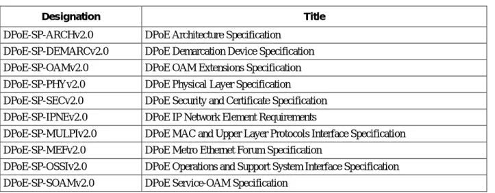
A list of the specifications included in the DPoE 2.0 series is provided in Table 1. For further information please refer to http://www.cablelabs.com/specs/specification-search/?cat=dpoe&scat=dpoe-2-0.
Table 1 - DPoE 2.0 Series of Specifications
Designation Title
DPoE-SP-ARCHv2.0 DPoE Architecture Specification DPoE-SP-DEMARCv2.0 DPoE Demarcation Device Specification DPoE-SP-OAMv2.0 DPoE OAM Extensions Specification DPoE-SP-PHYv2.0 DPoE Physical Layer Specification
DPoE-SP-SECv2.0 DPoE Security and Certificate Specification DPoE-SP-IPNEv2.0 DPoE IP Network Element Requirements
DPoE-SP-MULPIv2.0 DPoE MAC and Upper Layer Protocols Interface Specification DPoE-SP-MEFv2.0 DPoE Metro Ethernet Forum Specification
DPoE-SP-OSSIv2.0 DPoE Operations and Support System Interface Specification DPoE-SP-SOAMv2.0 DPoE Service-OAM Specification
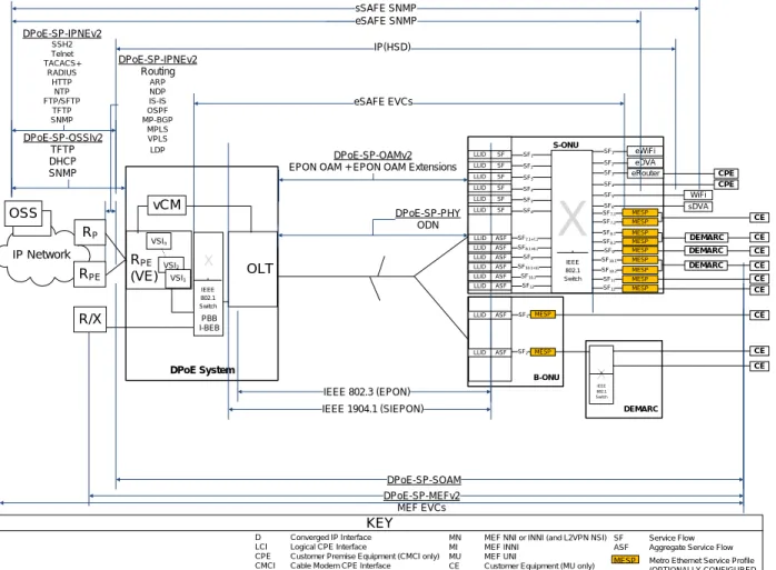
1.6 Reference Architecture
The DPoE reference architecture shown in Figure 1 identifies the elements that a DPoE Network minimally requires to illustrate and communicate the physical hardware and logical software interfaces between the functional
subsystems of the DPoE architecture. The principal elements in the architecture are the DPoE System that resides in the headend or hub site, and the DPoE ONU (D-ONU) which may be an off-the-shelf EPON ONU, EPON SFP-ONU, or an EPON ONU with additional subsystems. The remaining elements in the architecture are existing servers and systems in the operator's network. All the server elements have connectivity through an IP (TCP/IP) network. Transport of bearer traffic, and (in some cases) Layer 2 OAM Protocol Data Units (PDUs) are available through either IP or Layer 2 Ethernet-based Network Interfaces.
DPoE-SP-IPNEv2 Routing ARP NDP IS-IS OSPF MP-BGP MPLS VPLS LDP
X
DPoE System IP Network R PE (VE) DPoE-SP-OSSIv2 TFTP DHCP SNMP DPoE-SP-MEFv2 MEF EVCs DPoE-SP-PHY ODN RPE RP S-ONU B-ONU eDVA IEEE 802.3 (EPON) DPoE-SP-IPNEv2 SSH2 Telnet TACACS+ RADIUS HTTP NTP FTP/SFTP TFTP SNMP OLT DPoE-SP-OAMv2 EPON OAM + EPON OAM ExtensionsR/X OSS DEMARC eRouter IP(HSD) DEMARC eSAFE EVCs X IEEE 802.1 Switch DEMARC sDVA eWiFi WiFi sSAFE SNMP eSAFE SNMP KEY IEEE 1904.1 (SIEPON) MESP MESP MESP MESP MESP MESP ASF MESP MESP MESP DPoE-SP-SOAM vCM LLID ASF LLID SF LLID SF LLID SF LLID SF LLID SF LLID SF LLID D Converged IP Interface LCI Logical CPE Interface
CPE Customer Premise Equipment (CMCI only) CMCI Cable Modem CPE Interface
MN MEF NNI or INNI (and L2VPN NSI) MI MEF INNI
MU MEF UNI
CE Customer Equipment (MU only)
SF Service Flow ASF Aggregate Service Flow
SF1 SF4 SF1 SF2 SF3 SF5 SF6 SF2 SF3 SF4 SF5 SF6 SF7.1 SF7.2 SF8.1 SF8.2 SF9 SF10.1 SF10.2 SF11 SF12 DEMARC ASF LLID SF10.2 ASF LLID SF12 ASF LLID SF10.1+11 ASF LLID SF9 ASF LLID SF8.1+8.2 ASF LLID SF7.1+7.2 SF1 SF2 MESP IEEE 802.1 Switch X IEEE 802.1 Switch PBB I-BEB CE CE CE CE CE CE CE CE CE CPE CPE MESP
MESP Metro Ethernet Service Profile (OPTIONALLY CONFIGURED VSIn
VSI2
VSI1
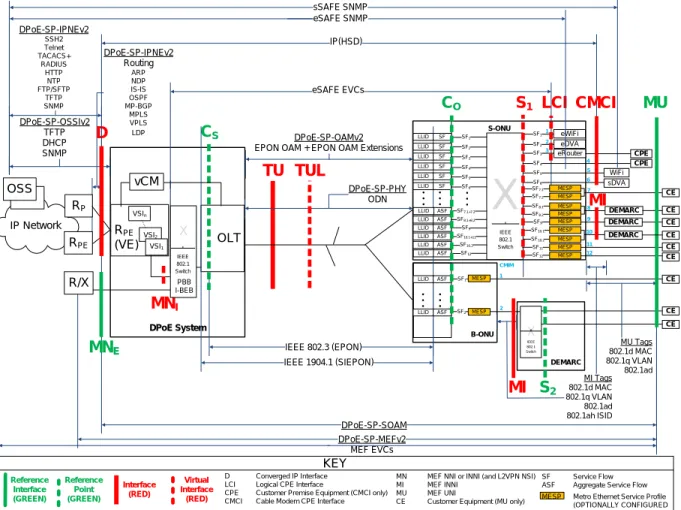
1.7 DPoE Interfaces and Reference Points
The DPoE interfaces and reference points shown in Figure 2 provide a basis for the description and enumeration of DPoE specifications for the DPoE architecture. Each interface or reference point indicates a point between separate subsystems. The reference points have protocols that run across them, or have a common format of bearer traffic (with no signaling protocol). All the interfaces are bi-directional interfaces that support two-way communications. The protocols in DPoE specifications operate within different layers based on the [802.3], [802.1], IETF, MEF, and CableLabs specifications. The C reference points are uni-directional for upstream (CO) or downstream (CS)
classification, respectively. DPoE-SP-IPNEv2 Routing ARP NDP IS-IS OSPF MP-BGP MPLS VPLS LDP
X
MI Tags 802.1d MAC 802.1q VLAN 802.1ad 802.1ah ISID DPoE System IP Network R PE (VE) DPoE-SP-OSSIv2 TFTP DHCP SNMP DPoE-SP-MEFv2 MEF EVCs DPoE-SP-PHY ODN RPE RP S-ONU B-ONU eDVA IEEE 802.3 (EPON) D TU DPoE-SP-IPNEv2 SSH2 Telnet TACACS+ RADIUS HTTP NTP FTP/SFTP TFTP SNMP OLT DPoE-SP-OAMv2 EPON OAM + EPON OAM ExtensionsR/X OSS MNI DEMARC S1 eRouter IP(HSD) DEMARC eSAFE EVCs X IEEE 802.1 Switch LCI DEMARC MI CO CS CMCI sDVA eWiFi WiFi sSAFE SNMP eSAFE SNMP KEY Reference Point (GREEN) Interface (RED) MU IEEE 1904.1 (SIEPON) TUL Virtual Interface (RED) MESP MESP MESP MESP MESP MESP ASF MESP MESP MESP DPoE-SP-SOAM Reference Interface (GREEN) vCM MU Tags 802.1d MAC 802.1q VLAN 802.1ad LLID ASF LLID SF LLID SF LLID SF LLID SF LLID SF LLID SF LLID D Converged IP Interface LCI Logical CPE Interface
CPE Customer Premise Equipment (CMCI only) CMCI Cable Modem CPE Interface
MN MEF NNI or INNI (and L2VPN NSI) MI MEF INNI
MU MEF UNI
CE Customer Equipment (MU only)
SF Service Flow ASF Aggregate Service Flow SF1 SF4 SF1 SF2 SF3 SF5 SF6 SF2 SF3 SF4 SF5 SF6 SF7.1 SF7.2 SF8.1 SF8.2 SF9 SF10.1 SF10.2 SF11 SF12 DEMARC 4 1 2 3 5 6 7 8 9 10 11 12 ASF LLID SF10.2 ASF LLID SF12 ASF LLID SF10.1+11 ASF LLID SF9 ASF LLID SF8.1+8.2 ASF LLID SF7.1+7.2 CMIM 1 2 SF1 SF2 MESP IEEE 802.1 Switch S2 MNE X IEEE 802.1 Switch PBB I-BEB MI CE CE CE CE CE CE CE CE CE CPE CPE MESP
MESP Metro Ethernet Service Profile (OPTIONALLY CONFIGURED VSIn
VSI2
VSI1
Table 2 - DPoEv2.0 Interface and Reference Point Descriptions
Interface or Reference Point
Interface or Reference Point Description
MN MN is a logical concept used for the specification of requirements for MEF INNI that apply to both MNE and MNI. MN logically provides the equivalent function of a MEF INNI or
L2VPN NSI. It is an NNI for Metro Ethernet services only.
MNE The MNE (MEF INNI External) interface is a substitute for the MN reference interface from
DPoE version 1.0 specifications. The MN interface is an [802.3] interface for Ethernet (or MEF or L2VPN emulated) services only. It serves the role of a MEF INNI or L2VPN NSI. It is an NNI for Metro Ethernet services only.
MNI The MNI reference interface is used to describe the virtual interface between an OLT and a
VPLS Virtual Switch Instance (VSI). In particular, it is used to describe the requirements for stitching VSIs to DPoE System and OLT [802.1] components such as [802.1d] bridge groups, [802.1ad] S-VLAN or C-VLAN (S-component or C-component), or [802.1ad] I-BEB (I-component) or B-I-BEB (B-component) backbone edge bridges. The DPoE System stitches VPLS and VPWS transport and forwarding for Metro Ethernet Services between the D interface and the MNI reference interface3.
D The D interface is the DOCSIS IP NNI interface. It is an operator network-facing interface, sometimes called a Network Systems Interface (NSI) in DOCSIS specifications. The D interface allows a DPoE System to communicate with an IP network. The D interface carries all IP management traffic including OSSI and IP NE traffic. The D interface carries all DOCSIS IP service traffic, IP/MPLS/VPLS traffic, and IP/MPLS/VPWS traffic. TU The TU interface is the interface between the DPoE System and the D-ONU.
TUL The TUL interface is a virtual interface representing a logical EPON on an ODN. Each ODN has at least one TUL, and each TUL represents a MAC domain.
C The C reference point is used for explanation of traffic ingress to a DPoE classifier. CO The CO reference point is used for explanation of traffic ingress to a D-ONU upstream
classifier.
CS The CS reference point is used for explanation of traffic ingress to a DPoE System
downstream classifier.
S The S interface is an IEEE 802 interface. The S interface may be an internal interface, such as [802.3] across a SERDES (GMII or XGMII) interface in a BP-ONU (such as an SFP-ONU, SFP+ONU or XFP-ONU), or it may be an external Ethernet interface in a BB-ONU or S-ONU.
S1 is an interface for an S-ONU. S2 is a reference point used for explanation of services with
the B-ONU.
S1 The S1 interfaces are the general case of all interfaces on an S-ONU. S1 interfaces may be
CMCI, LCI, MI, or MU interfaces.
S2 The S2 reference point is used for explanation of traffic ingress to and egress from interfaces
on a DEMARC device in a DPoE System. Although there are no specifications or requirements for the S2 reference point, informative text refers to the S2 reference point to
provide the full context for the use of a B-ONU with a DEMARC device providing Metro Ethernet services.
3
MNI is required for IP-based forwarding and transport of Metro Ethernet services with DPoE in order to provide MEF E-LAN
and E-TREE services described in DPoE version 2.0. While these services can be constructed with MNE, these specifications do
Interface or Reference Point
Interface or Reference Point Description
LCI The Logical CPE Interface (LCI) interface is an eDOCSIS interface as defined in [eDOCSIS]. eSAFEs are connected to LCI interfaces.
CMCI CMCI is the DPoE interface equivalent of the DOCSIS Cable Modem CPE Interface as defined in [CMCIv3.0]. This is the service interface for DOCSIS-based IP services. Customer Premise Equipment (CPE) is connected to CMCI interfaces.
MI MI is an S interface that operates as a MEF INNI with additional requirements as specified in [DPoE-MEFv2.0]. The MI interface is an [802.3] interface (or reference point) between a D-ONU and a DEMARC device.
• A D-ONU that provides a MEF INNI has an MI interface.
• A D-ONU can have MU as an interface and an MI reference point on different S interfaces in a single D-ONU.
DEMARC devices are connected to MI interfaces.
MU MU is an S interface (or S reference interface) that operates as a MEF UNI. The MU reference interface is an [802.3] interface (or reference point) between a D-ONU or a DEMARC device and a customer's equipment.
• A D-ONU that directly provides a MEF UNI (MU) interface has MU as an interface.
• A D-ONU can have MU as an interface and an MI reference point on different S interfaces in a single D-ONU.
2 REFERENCES
42.1 Normative References
In order to claim compliance with this specification, it is necessary to conform to the following standards and other works as indicated, in addition to the other requirements of this specification. Notwithstanding, intellectual property rights may be required to use or implement such normative references. At the time of publication, the editions indicated were valid. All references are subject to revision, and users of this document are encouraged to investigate the possibility of applying the most recent editions of the documents listed below. References are either specific (identified by date of publication, edition number, version number, etc.) or non-specific. For a non-specific reference, the latest version applies.
In this specification, terms "802.1ad" and "802.1ah" are used to indicate compliance with the [802.1ad] and [802.1ah] standards, respectively, now incorporated as part of [802.1Q]. For all intents and purposes, claiming compliance to [802.1Q], [802.1ad] or [802.1ah] in the scope of this specification will be treated as claiming compliance to IEEE Std 802.1Q-2011. Unless otherwise stated, claiming compliance to 802.1q-2005 requires a specific date reference.
[1904.1A] IEEE Std 1904.1™-2013, IEEE Standard for Service Interoperability in Ethernet Passive Optical Networks (SIEPON), Package A.
[802.1] Refers to entire suite of IEEE 802.1 standards unless otherwise specified.
[802.1ad] IEEE Std 802.1ad-2005™, IEEE Standard for Local and Metropolitan Area Networks – Virtual Bridged Local Area Networks Amendment 4: Provider Bridges, May 2006. Former amendment to 802.1Q, now part of 802.1Q-2011.
[802.1ah] IEEE Std 802.1ah-2008, IEEE Standard for Local and Metropolitan Area Networks – Virtual Bridged Local Area Networks – Amendment 6: Provider Backbone Bridges, January 2008. Former amendment to 802.1Q, now part of 802.1Q-2011.
[802.1d] IEEE Std 802.1d™-2004, IEEE Standard for Local and Metropolitan Area Networks: Media Access Control (MAC) Bridges.
[802.1p] IEEE Std 802.1p (2004), LAN Layer 2 QoS/CoS Protocol For Traffic Prioritization. [802.1Q] IEEE Std 802.1Q-2011, IEEE Standard for Local and Metropolitan Area Networks -
Media Access Control (MAC) Bridges and Virtual Bridge Local Area Networks, August 2011.
[802.3] IEEE Std 802.3-2012, IEEE Standard for Ethernet, December 2012. [802.3ah] IEEE Std 802.3ah™-2004, IEEE Standard for Information
technology-Telecommunications and information systems-Local and metropolitan area networks-Specific requirements, Part 3: Carrier Sense Multiple Access with Collision Detection (CSMA/CD) Access Method and Physical Layer Specifications, Amendment: Media Access Control Parameters, Physical Layers, and Management Parameters for Subscriber Access Networks, now part of [802.3].
[802.3as] IEEE Std 802.3as™-2006. Amendment 3 to IEEE Standard for Information technology-Telecommunications and information exchange between systems-Local and metropolitan area networks-Specific requirements-Part 3: Carrier Sense Multiple Access with Collision Detection (CSMA/CD) Access Method and Physical Layer Specifications Amendment 3, November 2006, now part of [802.3].
4
[802.3av] IEEE Std 802.3av™-2009, IEEE Standard for Information
technology-Telecommunications and information systems-Local and metropolitan area networks-Specific requirements, Part 3: Carrier Sense Multiple Access with Collision Detection (CSMA/CD) Access Method and Physical Layer Specifications Amendment 1: Physical Layer Specifications and Management Parameters for 10Gb/s Passive Optical Networks, now part of [802.3].
[1588v2] IEEE Std 1588™-2008, IEEE Standard for a Precision Clock Synchronization Protocol for Networked Measurement and Control Systems.
[CANN-DHCP-Reg] CableLabs' DHCP Options Registry, CL-SP-CANN-DHCP-Reg,
http://www.cablelabs.com/specification/cablelabs-dhcp-options-registry-2/, Cable Television Laboratories, Inc.
[CMCIv3.0] Data-Over-Cable Service Interface Specifications, Cable Modem to Customer Premise Equipment Interface Specification, CM-SP-CMCIv3.0,
http://www.cablelabs.com/specification/docsis-cable-modem-to-cpe-interface-specification/, Cable Television Laboratories, Inc.
[DOCSIS] Refers to entire suite of DOCSIS 3.0 specifications unless otherwise specified.
[DPoE-ARCHv2.0] DOCSIS Provisioning of EPON, DPoE Architecture Specification, DPoE-SP-ARCHv2.0, http://www.cablelabs.com/specification/dpoe-architecture-specification-2/, Cable
Television Laboratories, Inc.
[DPoE-DEMARCv2.0] DOCSIS Provisioning of EPON, DPoE Demarcation Device Specification, DPoE-SP-DEMARCv2.0, Cable Television Laboratories, Inc.
[DPoE-IPNEv2.0] DOCSIS Provisioning of EPON, IP Network Element Requirements, DPoE-SP-IPNEv2.0, http://www.cablelabs.com/specification/dpoe-ip-network-elements-requirements/, Cable Television Laboratories, Inc.
[DPoE-MEFv2.0] DOCSIS Provisioning of EPON, Metro Ethernet Forum Specification, DPoE-SP-MEFv2.0, http://www.cablelabs.com/specification/dpoe-metro-ethernet-forum-specification-2/, Cable Television Laboratories, Inc.
[DPoE-OAMv2.0] DOCSIS Provisioning of EPON, OAM Extensions Specification, DPoE-SP-OAMv2.0, http://www.cablelabs.com/specification/dpoe-oam-extensions-specification-2/, Cable Television Laboratories, Inc.
[DPoE-OSSIv2.0] DOCSIS Provisioning of EPON, Operations and Support System Interface Specification, http://www.cablelabs.com/specification/dpoe-operations-and-support-system-interface-specification-3/, DPoE-SP-OSSIv2.0, Cable Television Laboratories, Inc.
[DPoE-PHYv2.0] DOCSIS Provisioning of EPON, Physical Layer Specification, DPoE-SP-PHYv2.0, http://www.cablelabs.com/specification/dpoe-physical-layer-specification-2/, Cable Television Laboratories, Inc.
[DPoE-SECv2.0] DOCSIS Provisioning of EPON, Security and Certificate Specification, DPoE-SP-SECv2.0, http://www.cablelabs.com/specification/dpoe-security-specification/, Cable Television Laboratories, Inc.
[DPoE-SOAMv2.0] DOCSIS Provisioning of EPON, DPoE Service OAM Specification, DPoE-SP-SOAMv2.0, http://www.cablelabs.com/specification/dpoe-service-oam-specification/, Cable Television Laboratories, Inc.
[eDOCSIS] Data-Over-Cable Service Interface Specifications, eDOCSIS Specification, CM-SP-eDOCSIS, http://www.cablelabs.com/specification/edocsis-specification/, Cable Television Laboratories, Inc.
[eRouter] Data-Over-Cable Service Interface Specifications, eRouter Specification, CM-SP-eRouter, http://www.cablelabs.com/specification/ipv4-and-ipv6-erouter-specification/, Cable Television Laboratories, Inc.
[L2VPN] Data-Over-Cable Service Interface Specifications, Layer 2 Virtual Private Networks, CM-SP-L2VPN, http://www.cablelabs.com/specification/business-services-over-docsis-layer-2-virtual-private-networks/, Cable Television Laboratories, Inc.
[MEF 10.2] Metro Ethernet Forum, Ethernet Services Attributes – Phase 2, October 2009. [MULPIv3.0] Data-Over-Cable Service Interface Specifications, MAC and Upper Layer Protocols
Interface Specification, CM-SP-MULPIv3.0, http://www.cablelabs.com/specification/mac-and-upper-layer-protocols-interface-specification/, Cable Television Laboratories, Inc. [RFC 2131] IETF RFC 2131, Dynamic Host Configuration Protocol, R. Droms, March 1997.
[RFC 2132] IETF RFC 2132, DHCP Options and BOOTP Vendor Extensions, S. Alexander, R. Droms, March 1997.
[RFC 3046] IETF RFC 3046, DHCP Relay Agent Information Option, January 2001.
[RFC 3315] IETF RFC 3315, R. Droms, Ed., J. Bound, B. Volz, T. Lemon, C. Perkins, M. Car, Dynamic Host Configuration Protocol for IPv6 (DHCPv6), July 2003.
[RFC 3376] IETF RFC 3376, B. Cain, S. Deering, I. Kouvelas, B. Fenner, A.Thyagarajan, Internet Group Management Protocol, Version 3, October 2002.
[RFC 3513] IETF RFC 3513, R. Hinden, S. Deering, Internet Protocol Version 6 (IPv6) Addressing Architecture, April 2003.
[RFC 3810] IETF RFC 3810, R. Vida, Ed., L. Costa, Ed. Multicast Listener Discovery Version 2 (MLDv2) for IPv6, June 2004.
[RFC 4361] IETF RFC 4361 Node-specific Client Identifiers for Dynamic Host Configuration, February 2006.
[RFC 4649] IETF RFC 4649, B. Volz, "Dynamic Host Configuration Protocol for IPv6 (DHCPv6) Relay Agent Remote-ID Option" August 2006.
[RFC 4862] IETF RFC 4862, S. Thomson, T. Narten, T. Jinmei, IPv6 Stateless Address Autoconfiguration, September 2007.
2.2 Informative References
This specification uses the following informative references.
[802.1ag] IEEE Std 802.1ag–2007™, IEEE Standard for Local and metropolitan Area Networks – Virtual Bridged Local Area Networks Amendment 5: Connectivity Fault Management, December 2007. [802.1ax] IEEE Std 802.1ax-2008, IEEE Standard for Local and Metropolitan Area Networks-Link
Aggregation, January 2008.
[MEF 6] Metro Ethernet Forum, MEF 6.1 Ethernet Services Definitions, Phase 2, April 2008. [MEF 9] Metro Ethernet Forum, Abstract Test Suite for Ethernet Services at the UNI, October 2004. [MEF 14] Metro Ethernet Forum, Abstract Test Suite for Traffic Management Phase 1, November 2005. [MEF 21] Metro Ethernet Forum, Service OAM and Requirements Framework, Phase 1, April 2007. [MEF 26] Metro Ethernet Forum, External Network to Network Interface (ENNI) – Phase 1, January 2010. [OSSIv3.0] Data-Over-Cable Service Interface Specifications, Operations Support System Interface
Specification, CM-SP-OSSIv3.0, http://www.cablelabs.com/specification/docsis-3-0-operations-support-system-interface-specification/, Cable Television Laboratories, Inc.
[PHYv3.0] Data-Over-Cable Service Interface Specifications, Physical Layer Specification, CM-SP-PHYv3.0, http://www.cablelabs.com/specification/docsis-3-0-physical-layer-interface-specification/, Cable Television Laboratories, Inc.
[RFC 2669] IETF RFC 2669, DOCSIS Cable Device MIB Cable Device Management Information Base for DOCSIS compliant Cable Modems and Cable Modem Termination Systems. August 1999. [RFC 2863] IETF RFC 2863, The Interfaces Group MIB, June 2000.
[RFC 3032] IETF RFC 3032, MPLS Label Stack Encoding, January 2001.
[RFC 3418] IETF RFC 3418/STD0062, Management Information Base (MIB) for the Simple Network Management Protocol (SNMP), June 2000.
[RFC 4188] IETF RFC 4188, Definitions of Managed Objects for Bridges, September 2005.
[RFC 4293] IETF RFC 4293, Management Information Base for the Internet Protocol (IP), April 2006.
[RFC 5462] IETF RFC 5462, Multiprotocol Label Switching (MPLS) Label Stack Entry: "EXP" Field Renamed to "Traffic Class" Field, February 2009.
[SCTE 174] ANSI/SCTE 174 2010, Radio Frequency over Glass Fiber-to-the-Home Specification. [SECv3.0] Data-Over-Cable Service Interface Specifications, Security Specification, CM-SP-SECv3.0,
http://www.cablelabs.com/specification/docsis-3-0-security-specification/, Cable Television Laboratories, Inc.
[SFF-8077i] SFF-8077i 10 Gigabit Small Form Factor Pluggable Module, Revision 4.0, released April 13, 2004. [SFF-8472] SFF-8472 Specification for Diagnostic Monitoring Interface for Optical Transceivers, Revision 10.4,
released January 2009.
[SFP MSA] INF 8074i Rev 1.0, Small Form-factor Pluggable Multi-Source Agreement, released 12 May 2001.
2.3 Reference Acquisition
• Cable Television Laboratories, Inc., 858 Coal Creek Circle, Louisville, CO 80027; Phone +1-303-661-9100; Fax +1-303-661-9199; http://www.cablelabs.com
• Internet Engineering Task Force (IETF) Secretariat, 48377 Fremont Blvd., Suite 117, Fremont, California 94538, USA, Phone: +1-510-492-4080, Fax: +1-510-492-4001, http://www.ietf.org
• Institute of Electrical and Electronics Engineers (IEEE), +1 800 422 4633 (USA and Canada); http://www.ieee.org
• SCTE, Society of Cable Telecommunications Engineers Inc., 140 Philips Road, Exton, PA 19341 Phone: +1-800-542-5040, Fax: +1-610-363-5898, Internet: http://www.scte.org/
3 TERMS AND DEFINITIONS
3.1 DPoE Network Elements
DPoE Network This term means all the elements of a DPoE implementation, including at least one
DPoE System, one or more D-ONUs connected to that DPoE System, and possibly one or more DEMARCs.
DPoE System This term refers to the set of subsystems within the hub site that provides the
functions necessary to meet DPoE specification requirements.
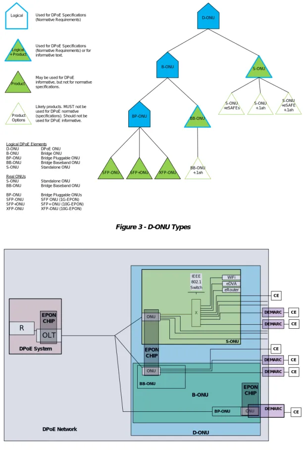
DPoE ONU (D-ONU) This term means a DPoE-capable ONU that complies with all the DPoE
specifications. There are two logical types of D-ONUs. These are the DPoE Standalone ONU (S-ONU) and the DPoE Bridge ONU (B-ONU). Requirements specified for a D-ONU must be met by all ONUs.
DPoE Standalone ONU (S-ONU)
This term means a D-ONU that provides all the functions of a B-ONU and also provides at least one CMCI port. An S-ONU can optionally have one or more eSAFEs.
DPoE Bridge ONU (B-ONU) This term means a D-ONU that is capable of [802.1] forwarding but cannot do all
the encapsulation functions required to be an S-ONU. The B-ONU is a logical definition used by the specification for requirements that apply to all types of B-ONUs. The two types of B-ONUs are the BP-ONU and the BB-ONU.
DPoE Bridge Pluggable ONU (BP-ONU)
This term means a D-ONU that is a B-ONU which is pluggable. Pluggable BP-ONUs include devices such as an SFP-ONU (1G-EPON), SFP+ONU (10G-EPON), or XFP-ONU (10G-EPON).
DPoE Bridge Baseband ONU (BB-ONU)
This term means a D-ONU that is a B-ONU which has a baseband IEEE Ethernet interface. BB-ONUs include those with one or more [802.3] baseband PMDs. (See [DPoE-ARCHv2.0], section 7.2.6.2 for examples.)
DEMARC Short form of "Demarcation Device." This term means the device, owned and
operated by the operator that provides the demarcation (sometimes called the UNI interface) to the customer. Some architectures describe this device as the CPE (as in DOCSIS) or the NID (as in the MEF model).
Product Logical D-ONU B-ONU S-ONU SFP-ONU BP-ONU SFP+ONU XFP-ONU S-ONU +eSAFEs S-ONU +.1ah S-ONU +eSAFE +.1ah Product Options
Logical DPoE Elements
D-ONU DPoE ONU
B-ONU Bridge ONU
BP-ONU Bridge Pluggable ONU BB-ONU Bridge Baseband ONU
S-ONU Standalone ONU
Real ONUs
S-ONU Standalone ONU
BB-ONU Bridge Baseband ONU BP-ONU Bridge Pluggable ONUs SFP-ONU SFP ONU (1G-EPON) SFP+ONU SFP+ ONU (10G-EPON) XFP-ONU XFP-ONU (10G-EPON)
Used for DPoE Specifications (Normative Requirements)
May be used for DPoE informative, but not for normative specifications.
Likely products. MUST not be used for DPoE normative (specifications). Should not be used for DPoE informative. Logical
+ Product
Used for DPoE Specifications (Normative Requirements) or for informative text.
BB-ONU
BB-ONU +.1ah
Figure 3 - D-ONU Types
DPoE System R ONU X S-ONU BB-ONU eDVA OLT ONU eRouter DEMARC IEEE 802.1 Switch DEMARC WiFi D-ONU EPON CHIP EPON CHIP ONU BP-ONU DEMARC B-ONU EPON CHIP DPoE Network DEMARC CE CE CE CE CE CE DEMARC CE
3.2 Other Terms and Definitions
51G-EPON EPON as first defined in [802.3ah], now part of [802.3].
10G-EPON EPON as first defined in [802.3av], now part of [802.3].
Address Resolution Protocol
A protocol of the IETF for converting network addresses to 48-bit Ethernet addresses.
Byte A contiguous sequence of eight bits. An octet.
Burst A single, continuous transmission in the upstream direction originating from a single
ONU, where queued customer data is transmitted towards the DPoE System at the full data rate supported by the transmission channel. Between bursts, ONUs do not transmit any data.
Cable Modem CPE Interface
CMCI as defined in [MULPIv3.0].
Classifier A set of criteria used for packet matching according to TCP, UDP, IP, LLC, [802.1p]
or [802.1Q] packet fields. A classifier maps each packet to a Service Flow. A Downstream classifier is used by the DPoE System to assign packets to downstream service flows. An Upstream classifier is used by The D-ONU to assign packets to upstream service flows.
Codeword An element of an error-correcting code used to detect and correct transmission errors.
Customer Premise Equipment (CPE)
Customer Premise Equipment as defined in [DOCSIS].
Data Link Layer Layer 2 in the Open System Interconnection (OSI) architecture; the layer that
provides services to transfer data over the transmission link between open systems (here, equal to EPON).
Data Rate Rate Throughput, data transmitted in units of time usually in bits per second (bps).
Various multipliers are used in this document, ranging from kbit/s (thousand bits per second) to Gbps (billion bits per second).
EPON Operations and Maintenance Messaging (OAM)
EPON OAM messaging as defined in [802.3] and [DPoE-OAMv2.0]; Ethernet OAM is not the same as EPON OAM; Ethernet OAM is defined in [802.1ag].
Ethernet Passive Optical
Network (EPON)
Refers to both 1G-EPON and 10G-EPON collectively.
Frame Basic data organizational unit. Here, equal to MAC frame per [802.3], Clause 4.
Logical CPE Interface LCI as defined in [eDOCSIS].
Network Interface Device (NID)
A DEMARC device in DPoE specifications.
Upstream The direction of transmission from the customer to the head-end.
5
4 ABBREVIATIONS AND ACRONYMS
This specification uses the following abbreviations:ASF Aggregate Service Flow
ASFID Aggregate Service Flow Identifier
ASF-REF Aggregate Service Flow Reference
BE Best Effort Service
B-DA Backbone MAC Destination Address
B-SA Backbone MAC Source Address
B-VID Backbone VLAN ID
CBS Committed Burst Size
CID Classifier IDs
CIR Committed Information Rate
CMCI Cable Modem CPE Interface as defined in [CMCIv3.0]
CMIM Cable Modem Interface Mask
CoS Class of Service
CPE Customer Premise Equipment
DAC DEMARC Automatic Configuration
DBA Dynamic Bandwidth Allocation
DCID Downstream Channel Identifier
DPM Dual-stack Provisioning Mode
DPoE DOCSIS Provisioning of EPON
DR Default Router
DUT Downstream Unencrypted Traffic
EBS Excess Burst Size
EIR Excess Information Rate
ENNI External Network to Network Interface
EPON Ethernet Passive Optical Network; refers to both 1G-EPON and 10G-EPON collectively
EToD EPON Time of Day
eSAFE embedded Service/Application Functional Entity
EVC Ethernet Virtual Connection
FEC Forward error correction
Gbps Gigabits per second (as used in the industry)
GSF Group Service Flows
IM Intensity Modulated
IP Internet Protocol
IP(HSD) High Speed Data Broadband Internet Access using DOCSIS
I-NNI Internal Network to Network Interface
I-SID [802.1ah] I-Component Service Identifier
IP-SG IP Serving Group
LLID Logical Link Identifier
LTE Logical Topology Emulation
mLLID multicast LLID
MEF Metro Ethernet Forum
MEN Metro Ethernet Network
MESP Metro Ethernet Service Profile
MESPID Metro Ethernet Service Profile Identifier
MESP-REF Metro Ethernet Service Profile Reference
MI MEF INNI Interface at a customer premise
MN MEF INNI Interface to operators MEN
MPCP Multi-Point Control Protocol
MPCPDU MPCP Data Unit
MSC Mobile Switching Center
MU MEF UNI Interface
NID Network Interface Device
NNI Network to Network Interface
NSI Network Systems Interface
OAM Operations Administration and Maintenance
OAMP Operations Administration Maintenance and Provisioning
ODN Optical Distribution Network
OLT Optical Line Termination
ONU Optical Network Unit
OSC Optical Splitter Combiner
OSI Open System Interconnection
P2MP Point to Multi-Point
P2P Point-to-Point
P2PE Point-to-Point Emulation
PB Provider Bridging [802.1ad]
PBB Provider Backbone Bridging [802.1ah]
PCS Physical Coding Sublayer
PDUs Protocol Data Units
PHY Physical Layer
PMA Physical Medium Attachment
PMD Physical Media Dependent (Sublayer)
PON Passive Optical Network
QoS Quality of Service
R IP Router
RAIO Relay Agent Information Option
RS Reconciliation Sublayer
RTPS Real Time Polling Service
SAO DPoE Standalone ONU
SCB Single Copy Broadcast
sDVA Standalone Digital Voice Adapter
SF Service Flow
SFID Service Flow Identifier
SFP Small Form-factor Pluggable
SFP+ SFTP
Small Form-factor Pluggable Plus (+) Secure File Transfer Protocol
SNMP Simple Network Management Protocol
TDM Time Division Multiplexing
TDMA Time Division Multiple Access
TFTP Trivial File Transfer Protocol
ToD Time of Day
TPID Tag Protocol Identifier
TQ Time Quanta
UCID Upstream Channel Identifier
UGS Unsolicited Grant Service
UNI User Network Interface
vCM Virtual Cable Modem
VFI Virtual Forwarding Instance
VSI Virtual Switch Instances
V-UNI Virtual-UNI
WSC Wireless Switching Center
X IEEE Ethernet Switch (Generic)
5 OVERVIEW AND THEORY OF OPERATIONS
5.1 MULPI Key Features
6DPoE specifications introduce a number of features that build upon features defined in the DOCSIS 3.0
specifications, as well as [802.3] EPON specifications, together with the series of other relevant specifications as listed in Section 2. This specification includes the following key new features for the MAC and Upper Layer Protocols Interface as compared to the DOCSIS 3.0 version [MULPIv3.0].
Downstream Channel transmission is operated using Time Division Multiplexing (TDM) transmission over EPON with Intensity Modulated signal. Channel Bonding [MULPIv3.0] is not supported in DPoE Networks, and
bandwidth is assigned to individual links or circuits on demand via the Dynamic Bandwidth Allocation (DBA) operating in the DPoE System. DPoE specifications building on 1G-EPON [802.3] offer an effective downstream bandwidth of approximately 960 Mbit/s (already accounting for transmission overhead, excluding optional Forward error correction (FEC) parity), while DPoE specifications building on 10G-EPON [802.3] offer an effective downstream bandwidth of approximately 8.9 Gbps (already accounting for transmission overhead, including mandatory FEC parity etc.). The downstream channel in DPoE Networks provides broadcast and multicast capability inherent for Point to Multi Point (P2MP) passive architecture of EPON.
Upstream Channel transmission is operated using Time Division Multiple Access (TDMA) transmission over EPONs with IM signal, where several D-ONUs connected to a single DPoE System time-share a single receiver to the upstream medium. Channel Bonding is not supported in DPoE Networks, and bandwidth is assigned to individual D-ONUs / logical entities on demand via the DBA operating at the DPoE System. DPoE specifications building on 1G-EPON [802.3] offer an effective upstream bandwidth of approximately 920 Mbit/s (already accounting for transmission overhead, including typical band gaps, excluding optional FEC parity), while DPoE specifications building on 10G-EPON [802.3] offer an effective upstream bandwidth of approximately 8.6 Gbps (already accounting for transmission overhead, including mandatory FEC parity and band gaps, etc.).
5.2 Technical Overview
This specification defines the MAC layer protocols of the DPoE Network elements, as well as requirements for upper layer protocols (IP, DHCP, etc.) operating on top of the EPON MAC. DPoE specifications introduce the EPON MAC as a substitute for the DOCSIS MAC in the DOCSIS specifications, reusing EPON MAC definitions for transmission of Ethernet encapsulated data over P2MP passive optical links.
EPON, and therefore DPoE specifications, do not support DOCSIS MAC-specific functions, such as:
• DOCSIS Dynamic Quality of Service (QoS) establishment and two-phase activation process;
• DOCSIS-specific load balancing;
• DOCSIS channel bonding in upstream and downstream channels;
• frame fragmentation at the transport layer;
6
5.2.1 Multicast Operation7
The DPoEv2.0 Specifications support IP multicast for IP(HSD) services by adopting the IP multicast model defined in [MULPIv3.0]. This model supports the delivery of Any Source Multicast (ASM) and Source-Specific Multicast (SSM) IP multicast streams to D-ONUs. As defined in [MULPIv3.0], the D-ONU is not aware of IP multicast control protocols. In DPoE specifications, the D-ONU does not proxy or snoop to track Layer-3 IP multicast group membership. Instead, all of the processing and management functionality related to multicast group membership is at the DPoE System.
The DPoE Network supports the provisioning and operation of IP multicast for IP(HSD) as defined in [MULPIv3.0], and this includes:
• Support for forwarding Source Specific Multicast traffic for IGMPv3 [RFC 3376] and MLDv2 [RFC 3810] CPE devices
• Support for forwarding Any Source Multicast traffic for IGMPv1/v2 and MLDv1 CPE devices
• Support for downstream multicast QoS
• Support for static multicast
• Support for downstream encrypted multicast
• Support for IPv4 and IPv6 multicast traffic
• Explicit tracking at the DPoE System of CPEs joined to a given multicast group
The following exceptions and differences from [MULPIv3.0] for support of IP multicast apply to this version of DPoE specifications:
• Upstream multicast is not defined in this version of the DPoE specification but the forwarding of upstream multicast traffic is not actively prevented. There is no upstream support defined for functionality such as multicast QoS or upstream multicast encryption.
• Pre-Registration IP multicast is not supported.
• Downstream Service ID (DSID) defined in [MULPIv3.0] is replaced with a multicast LLID (mLLID). 5.2.2 Network and Higher Layer Protocols
The DPoE System MUST perform (Ethernet) MAC Layer bridging and Network Layer routing of data traffic. The D-ONU MUST perform only MAC layer bridging of data traffic. However, both DPoE System and D-ONU are network-layer and transport-layer aware. Specifically, the DPoE System and D-ONU support classifying user traffic, based on operator configured set of criteria, including network layer and transport layer information among others, for purposes of providing QoS and packet filtering.
Additionally, the DPoE System MUST support the following protocols for operation and management:
• SNMP,
• TFTP, used by the DPoE System for downloading operational software and configuration information,
• SFTP, used by the DPoE System as a file transfer method for DEMARC Automatic Configuration.
7
DHCPv4 and DHCPv6, used by the DPoE System to obtain IP addresses and other configuration for D-ONU for vCM and DEMARC provisioning and management.
5.2.3 vCM, D-ONU, and CPE Provisioning and Management
5.2.3.1 Initialization, Provisioning and Management of CMs8
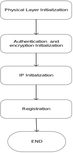
During initialization, the D-ONU goes through a number of steps before becoming fully operational in the DPoE Network. The full initialization comprises the same four fundamental stages specified for a DOCSIS CM:
1. Topology resolution and physical layer initialization 2. Authentication and encryption initialization
3. IP initialization
4. Registration (MAC layer initialization) The D-ONU initialization is shown in Figure 5.
Figure 5 - D-ONU Initialization
8
Revised per MULPIv2.0-N-14.0172-1 on 7/16/14 by JB.
Authentication and encryption Initialization
IP Initialization
Registration
END
The first stage, topology resolution and physical layer initialization, is specified in [DPoE-PHYv2.0], which describes the DPoE Network relationship to EPON system specifications. The 1G-EPON specifications were released first in [802.3ah], while higher speed 10G-EPON specifications were released first in [802.3av]. Both specifications are now part in [802.3].
The second stage, authentication and encryption, is specified in [DPoE-SECv2.0], which describes how security is implemented in a DPoE Network.
The third stage, IP Initialization, requires the assignment of an IPv4, IPv6, or IPv4 and IPv6 address to a vCM. Depending on the capabilities of the OSSI system, this enables management of the D-ONU through the vCM. Since the D-ONU does not contain an IP stack (i.e., not directly addressable using IP), the vCM MUST obtain an IP address and CM configuration file from the OSS provisioning systems, on behalf of the D-ONU, as part of the registration process.
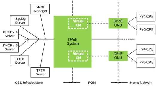
As described in [DPoE-OSSIv2.0], the DPoE System MUST provide management capabilities on behalf of the D-ONU for all IP-based management functions when the OSS management systems direct management requests to a given D-ONU. The concept of a virtual Cable Modem (vCM) is used in this specification to represent the IP-addressable management entity maintained and controlled within the DPoE System; one vCM is maintained per D-ONU. See Figure 6. The vCM is used to map requirements that were previously required of the DOCSIS Cable Modem to requirements on the DPoE System. Note that all requirements written against the vCM are understood to be directly interpreted as DPoE System requirements.
When the DPoE System receives management requests destined to a vCM, it checks whether the given management request requires interaction with the D-ONU. If no interaction is needed the request is handled locally, but if the request requires an extended Operations Administration and Maintenance (eOAM) message exchange between the DPoE System and the D-ONU, it converts those requests into the appropriate eOAM messages, and sends the eOAM requests to the corresponding D-ONU as needed. See [DPoE-OAMv2.0] for a full description of the DPoE OAM messaging.
Figure 6 - vCM within the DPoE network
SNMP Manager Syslog Server DHCPv 4 Server DHCPv 6 Server Time Server TFTP Server
OSS Infrastructure PON Home Network
DPoE System DPoE ONU IPv4 CPE IPv6 CPE DPoE ONU IPv4 CPE IPv6 CPE Virtual CM Virtual CM
The DPoE System uses DHCPv4 to acquire an IPv4 address and/or uses DHCPv6 to acquire an IPv6 address. This step is followed by TFTP to obtain D-ONU operational parameters. To facilitate compatibility with existing provisioning systems, this process is identical to the DOCSIS CM provisioning process and is further described in Section 9.
The fourth stage, registration, involves the DPoE System processing the CM configuration file. The DPoE System validates the contents and configures the DPoE System and D-ONU based on the service provisioning information in the CM configuration file. The vCM is used by the DPoE System to store the registration state, as well as the configuration of the D-ONU.
After the DPoE System completes initialization, the vCM is a manageable network element in the operator's IP network. The vCM supports SNMP (as mentioned above), and responds to queries directed to the IPv4 and/or IPv6 address that it acquired during initialization.
5.2.3.2 Initialization, Provisioning, and Management of CPEs9
DOCSIS specifications assume the use of DHCP for provisioning of CPE devices (per [DPoE-ARCHv2.0]). To that end, the DPoE System MUST support a DHCP Relay Agent that allows the operator to associate a CPE IP address (DHCP) request with the customer D-ONU MAC address. This feature is also used as the basis of a mechanism that prevents spoofing of IP addresses.
If a CPE client DCHPDISCOVER is received by the DPoE System on an upstream service flow that is configured in an IP-SG, the DPoE System relay agent MUST set the giaddr field in accordance with the IP parameter specified in the IP-SG.
5.2.3.3 Relationship between CMIM and D-ONU Ports
The Cable Modem Interface Mask (CMIM) is a bit mask representing the interfaces of the D-ONU from which the D-ONU classifies traffic in the upstream and sends traffic to on the downstream. These interfaces include both physical ports and Logical CPE Interfaces (LCI) on the D-ONU. Any of the classifier configuration related to these interfaces is provisioned using the CMIM. The vCM is responsible for translating between a CMIM-bit position and the corresponding port on the D-ONU, this translation is needed as the eOAM uses port numbers.
5.2.4 Relationship to the Physical Plant Topology
The DPoE Network uses an all-fiber passive Optical Distribution Network (ODN). Typically there are no active elements in the ODN. The ODN elements include optical splitter/combiners, connectors, and fiber.
In the DPoE Network, a MAC Domain is defined as a shared group of upstream and downstream channels on the same logical TU interface (TUL) that require the use of a shared scheduling algorithm for all D-ONUs on those channels. The DPoE System MUST allocate unique LLIDs for all D-ONUs within the same MAC Domain. The concept of MAC Domain in the DPoE Network is used for the purpose of compatibility with [OSSIv3.0] functions and to support 1G/10G coexistence. A DPoE System MUST represent each TUL as a single MAC Domain to the DOCSIS OSS in order to provide backwards compatibility with [MULPIv3.0]. A DPoE System MUST have at least one TUL per TU.
The DPoE System MUST ensure the following for a MAC Domain:
• Each D-ONU belongs to one and only one MAC Domain.
• Each downstream channel belongs to one and only one MAC Domain.
• Each upstream channel belongs to one and only one MAC Domain.
• A MAC Domain can contain multiple downstream channels.
9
• For the purposes of compatibility with [OSSIv3.0] functions, an 8-bit Downstream Channel ID (DCID) is assigned by the DPoE System to each downstream channel within a MAC Domain. Similar to the definition within [MULPIv3.0], the DCID value is unique within the scope of a particular MAC Domain.
• A MAC Domain can contain multiple upstream channels.
• For the purposes of compatibility with [OSSIv3.0] functions, an 8-bit Upstream Channel ID (UCID) is assigned by the DPoE System to each upstream channel within a MAC Domain. Similar to the definition within
[MULPIv3.0], the UCID value is unique within the scope of a particular MAC Domain.
The DPoE Network implements the necessary [DOCSIS] functionality primarily through the proxy of these functions on the DPoE System, which operates a vCM in place of a CM to emulate the function of the CM for management purposes in a DPoE Network. In DOCSIS specifications, the MAC Domain is used to directly manage CMs in the MAC Domain, without respect to the IP address of the CM. Likewise, the DPoE specification uses MAC domains to directly manage services on the D-ONU.
5.2.4.1 Examples of MAC Domain Relationship to the Physical Plant Topology
Although this specification does not explicitly mandate the number of MAC Domains to associate with a particular physical plant topology, this section provides examples of the relationship between MAC Domain and various DPoE Network topologies.
These examples define a TU interface with various combinations of 1G and 10G downstream channels, with never more than one of each type of channel available on a TU interface. Therefore, the wavelength bands of the
downstream channels do not overlap and the output from the transmitters can be multiplexed using a WDM coupler. 10G downstream channel using the 1575-1580 nm wavelength band
1G downstream channel using the 1480-1500 nm wavelength band
The examples also include various combinations of 1G and 10G upstream channels. Depending on the 1G wavelength band in use, the upstream channels may overlap. If they overlap, a scheduler treats them as a single channel, only allowing one D-ONU transmitter of either type to be active at a time.
10G upstream channel using the 1260-1280 nm wavelength band 1G upstream channel using the 1260-1360 nm wavelength band
The first column in the table below identifies the type of downstream channels available on a particular TU interface. The second column identifies the type of upstream channels in use or planned on the same TU interface. The third column identifies the number of MAC Domains that a vendor or operator may want to associate with the TU interface given the number and type of channels available.
Downstreams in TU Upstreams in TU MDs (TULs) in TU
1G 1G 1 10G 1G 1 10G 10G 1 10G 10G and 1G overlapping 1 10G 10G and 1G non-overlapping 1 10G and 1G 1G 1
10G and 1G 10G and 1G overlapping 1


![Table 3 details which parameters are applicable for an Upstream Service Flow, according to its configured Upstream Scheduling Service Type per [MULPIv3.0]](https://thumb-us.123doks.com/thumbv2/123dok_us/9682327.2456798/44.918.153.765.299.656/parameters-applicable-upstream-service-according-configured-upstream-scheduling.webp)