Data-Over-Cable Service Interface Specifications
DOCSIS 3.1
Cable Modem Operations Support System Interface
Specification
CM-SP-CM-OSSIv3.1-I02-141016
ISSUED
Notice
This DOCSIS® specification is the result of a cooperative effort undertaken at the direction of Cable Television Laboratories, Inc. for the benefit of the cable industry and its customers. You may download, copy, distribute, and reference the documents herein only for the purpose of developing products or services in accordance with such documents, and educational use. Except as granted by CableLabs® in a separate written license agreement, no license is granted to modify the documents herein (except via the Engineering Change process), or to use, copy, modify or distribute the documents for any other purpose. This document may contain references to other documents not owned or controlled by CableLabs. Use and understanding of this document may require access to such other documents. Designing, manufacturing, distributing, using, selling, or servicing products, or providing services, based on this document may require intellectual property licenses from third parties for technology referenced in this document. To the extent this document contains or refers to documents of third parties, you agree to abide by the terms of any licenses associated with such third party documents, including open source licenses, if any.
DISCLAIMER
This document is furnished on an "AS IS" basis and neither CableLabs nor its members provides any representation or warranty, express or implied, regarding the accuracy, completeness, noninfringement, or fitness for a particular purpose of this document, or any document referenced herein. Any use or reliance on the information or opinion in this document is at the risk of the user, and CableLabs and its members shall not be liable for any damage or injury incurred by any person arising out of the completeness, accuracy, or utility of any information or opinion contained in the document.
CableLabs reserves the right to revise this document for any reason including, but not limited to, changes in laws, regulations, or standards promulgated by various entities, technology advances, or changes in equipment design, manufacturing techniques, or operating procedures described, or referred to, herein.
This document is not to be construed to suggest that any company modify or change any of its products or procedures, nor does this document represent a commitment by CableLabs or any of its members to purchase any product whether or not it meets the characteristics described in the document. Unless granted in a separate written agreement from CableLabs, nothing contained herein shall be construed to confer any license or right to any intellectual property. This document is not to be construed as an endorsement of any product or company or as the adoption or promulgation of any guidelines, standards, or recommendations.
Document Status Sheet
Document Control Number: CM-SP-CM-OSSIv3.1-I02-141016
Document Title: Cable Modem Operations Support System Interface Specification
Revision History: I01 - Released 06/19/2014
I02 - Released 10/16/2014
Date: October 16, 2014
Status: Work in
Progress
Draft Issued Closed
Distribution Restrictions: Author Only CL/Member CL/ Member/
Vendor
Public
Key to Document Status Codes:
Work in Progress An incomplete document, designed to guide discussion and generate feedback
that may include several alternative requirements for consideration.
Draft A document in specification format considered largely complete, but lacking
review by Members and vendors. Drafts are susceptible to substantial change during the review process.
Issued A generally public document that has undergone Member and Technology
Supplier review, cross-vendor interoperability, and is for Certification testing if applicable. Issued Specifications are subject to the Engineering Change Process.
Closed A static document, reviewed, tested, validated, and closed to further engineering
change requests to the specification through CableLabs.
Trademarks
CableLabs® is a registered trademark of Cable Television Laboratories, Inc. Other CableLabs marks are listed at
Contents
1 SCOPE ... 11
1.1 Introduction and Purpose ... 11
1.2 Background ... 11
1.2.1 Broadband Access Network ... 11
1.2.2 Network and System Architecture ... 12
1.2.3 Service Goals ... 13 1.2.4 Statement of Compatibility ... 13 1.2.5 Reference Architecture ... 14 1.2.6 DOCSIS 3.1 Documents ... 14 1.3 Requirements ... 15 1.4 Conventions ... 15 1.5 Organization of Document ... 15 1.5.1 Annexes (Normative)... 16 1.5.2 Appendices (Informative) ... 16 2 REFERENCES ... 17 2.1 Normative References... 17 2.2 Informative References ... 19 2.3 Reference Acquisition... 19
3 TERMS AND DEFINITIONS ... 21
4 ABBREVIATIONS AND ACRONYMS ... 24
5 OVERVIEW... 29
5.1 DOCSIS 3.1 OSSI Key Features ... 29
5.1.1 Fault Management Features ... 29
5.1.2 Configuration Management Features ... 30
5.1.3 Performance Management Features ... 30
5.1.4 Security Management Features ... 30
5.1.5 Accounting Management Features ... 30
5.2 Technical Overview ... 30
5.2.1 Architectural Overview ... 30
5.2.2 Management Protocols ... 32
5.2.3 Information Models... 32
6 OSSI MANAGEMENT PROTOCOLS ... 34
6.1 SNMP Protocol ... 34
6.1.1 Requirements for IPv6 ... 35
7 OSSI MANAGEMENT OBJECTS ... 36
7.1 SNMP Management Information Bases (MIBS) ... 36
7.1.1 CableLabs MIB Modules ... 36
7.1.2 IETF RFC MIB Modules ... 37
7.1.3 Managed objects requirements ... 38
8 OSSI FOR PHY, MAC AND NETWORK LAYERS ... 47
8.1 Fault Management ... 47
8.1.1 SNMP Usage ... 47
8.1.2 Event Notification ... 47
8.1.3 Throttling, Limiting and Priority for Event, Trap and Syslog ... 52
8.2 Configuration Management ... 59
8.2.1 Version Control ... 59
8.2.2 System Configuration ... 60
8.2.3 Secure Software Download ... 60
8.2.4 CM configuration files, TLV-11 and MIB OIDs/values ... 65
8.3 Accounting Management ... 67
8.3.1 Subscriber Usage Billing and class of services ... 67
8.4 Performance Management ... 68
8.4.1 Treatment and interpretation of MIB counters ... 68
8.5 Security Management ... 69
8.5.1 CM SNMP Modes of Operation ... 69
8.5.2 CM SNMP Access Control Configuration ... 69
9 OSSI FOR CMCI ... 81
9.1 SNMP Access via CMCI ... 81
9.2 Console Access ... 81
9.3 CM Diagnostic Capabilities ... 82
9.4 Protocol Filtering ... 82
10 OSSI FOR LED INDICATORS ... 83
10.1 CM LED Requirements and Operation ... 83
10.1.1 Power On, Software Application Image Validation and Self Test ... 83
10.1.2 Scan for Downstream Channel ... 83
10.1.3 Resolve CM-SG and Range ... 84
10.1.4 Operational ... 84
10.1.5 Data Link and Activity ... 84
10.2 Additional CM Operational Status Visualization Features ... 84
10.2.1 Secure Software Download ... 85
ANNEX A DETAILED MIB REQUIREMENTS (NORMATIVE) ... 86
A.1 MIB-Object Details ... 86
A.2 [RFC 2863] ifTable/ifXTable MIB-Object Details... 122
ANNEX B APPLICATION OF IETF MULTICAST MIBS (NORMATIVE) ... 128
B.1 MGMD MIBs ... 128
B.2 CM Support of IGMP-STD-MIB [RFC 2933] ... 128
B.2.1 IGMP Interface Table Objects ... 128
B.2.2 igmpCacheTable ... 130
ANNEX C PROTOCOL FILTERING (NORMATIVE) ... 132
C.1 Filtering Mechanisms ... 132
C.1.1 LLC Filters... 132
C.1.2 Special filters ... 132
C.1.3 IP Protocol Filtering ... 134
C.1.4 Protocol Classification through Upstream Drop Classifiers ... 134
ANNEX D FORMAT AND CONTENT FOR EVENT, SYSLOG, AND SNMP NOTIFICATION (NORMATIVE) ... 139
ANNEX E PROACTIVE NETWORK MAINTENANCE REQUIREMENTS (NORMATIVE) ... 160
E.1 Overview ... 160
E.2 Enhanced Signal Quality Monitoring Object Definitions ... 160
E.2.1 Type Definitions ... 160
E.2.2 CM Spectrum Analysis Objects ... 162
E.2.3 CmSymbolCapture Object ... 166
E.2.5 CmDsConstDispMeas Object ... 171
E.2.6 CmDsOfdmRxMer Object ... 173
E.2.7 CmDsOfdmSnrMarForProfile Object... 174
E.2.8 CmDsOfdmRequiredQamMer Object ... 176
E.2.9 CmDsHist Object ... 177
E.2.10 CmUsEq Object ... 180
E.3 CM Bulk Data Transfer ... 183
E.3.1 Bulk Data Transfer Requirements ... 183
E.3.2 Data-File and Storage Requirements ... 183
E.3.3 CM Bulk Data Objects ... 184
ANNEX F DOCSIS 3.1 DATA TYPE DEFINITIONS (NORMATIVE) ... 187
F.1 Overview ... 187
F.2 Data Type Mapping ... 187
F.2.1 Data Type Requirements and Classification ... 187
F.2.2 Data Type Mapping Methodology ... 187
F.2.3 General Data Types ... 188
F.2.4 Extended Data Types ... 188
ANNEX G CM STATUS REPORTING REQUIREMENTS (NORMATIVE) ... 190
G.1 Overview ... 190
G.2 CM Operational Status Object Definitions ... 190
G.2.1 Overview ... 190
G.2.2 Type Definitions ... 190
G.2.3 CM Operational Status Objects ... 194
G.3 CM Downstream and Upstream Interfaces Information Models ... 205
G.3.1 DS US Common Data Type Definitions ... 205
G.3.2 CM Downstream Interface Information Model... 206
G.3.3 CM Upstream Interface Information Model ... 215
ANNEX H MAC AND UPPER LAYER PROTOCOLS INTERFACE (MULPI) REQUIREMENTS (NORMATIVE) ... 224
H.1 Overview ... 224
H.1.1 Cable Modem Service Groups (CM-SGs) ... 224
H.1.2 Downstream Bonding Group (DBG) ... 224
H.1.3 Upstream Bonding Group (UBG) ... 224
H.2 Object Definitions ... 224
H.2.1 Type Definitions ... 224
H.2.2 RCC Status Objects ... 227
H.2.3 DOCSIS QoS Objects... 230
H.2.4 QoS Statistics Objects ... 251
H.2.5 DSID Objects ... 260
H.2.6 CM Provisioning Objects ... 264
APPENDIX I SPECTRUM ANALYSIS USE CASES (INFORMATIVE) ... 268
I.1 Normalization of RF Impairment Measurements ... 268
I.1.1 Use Case 1: Figure of Merit Estimation for Logical Upstream Channel ... 269
I.1.2 Use Case 2: Figure of Merit Estimation per CM ... 269
I.1.3 Use Case 3: Absolute Noise and Interference Estimation ... 270
APPENDIX II INFORMATION MODEL NOTATION (INFORMATIVE) ... 271
II.1 Overview ... 271
II.2 Information Model Diagram ... 271
II.2.4 Dependencies ... 272
II.2.5 Comment ... 272
II.2.6 Diagram Notation ... 272
II.3 Object Instance Diagram ... 272
II.4 ObjectA Definition Example ... 273
II.4.1 AttributeA1 ... 273
II.4.2 AttributeA2 ... 273
II.4.3 AttributeA3 ... 273
II.5 Common Terms Shortened ... 274
II.5.1 Exceptions ... 275
APPENDIX III ACKNOWLEDGEMENTS (INFORMATIVE) ... 276
APPENDIX IV REVISION HISTORY ... 277
Figures
Figure 1–1 - The DOCSIS Network ... 12Figure 1–2 - Transparent IP Traffic through the Data-Over-Cable System ... 13
Figure 1–3 - Data-over-Cable Reference Architecture ... 14
Figure 5–1 - CM Management Architecture ... 31
Figure 7–1 - ifIndex example for CM ... 41
Figure 8–1 - Manufacturer control scheme ... 61
Figure 8–2 - Operator control scheme ... 61
Figure E–1 - Proactive Network Maintenance Information Model Diagram ... 160
Figure E–2 - Bulk Data Upload Information Model Diagram ... 184
Figure G–1 - CM Operational Status Information Model Diagram ... 194
Figure G–2 - CM Downstream Information Model Diagram ... 207
Figure G–3 - CM Upstream Information Model Diagram ... 216
Figure H–1 - RCC Status Information Model Diagram ... 227
Figure H–2 - QoS Configuration Information Model Diagram ... 230
Figure H–3 - QoS Statistics Information Model Diagram ... 251
Figure H–4 - DSID Information Model Diagram ... 260
Figure H–5 - CM MAC Domain Configuration Information Model Diagram ... 264
Figure II–1 - Information Model UML Class Diagram Notation ... 272
Figure II–2 - Object Instance Diagram for ObjectA ... 273
Tables
Table 1–1 - DOCSIS 3.1 Series of Specifications ... 14Table 1–2 - DOCSIS 3.1 Related Specifications ... 14
Table 5–1 - Management Feature Requirements for DOCSIS 3.1 ... 29
Table 6–1 - IETF SNMP-related RFCs ... 34
Table 6–2 - SMIv2 IETF SNMP-related RFCs ... 34
Table 6–3 - Diffie-Helman IETF SNMP-related RFC... 34
Table 7–1 - CableLabs MIB Modules ... 37
Table 7–3 - CM interface numbering ... 41
Table 7–4 - CmStatusValue and ifOperStatus relationship ... 42
Table 7–5 - USB State and ifOperStatus relationship... 42
Table 8–1 - CM default event reporting mechanism versus priority ... 51
Table 8–2 - Event Priority Assignment for CMs ... 51
Table 8–3 - SNMPv3 Notification Receiver TLV Mapping ... 53
Table 8–4 - snmpNotifyTable ... 53 Table 8–5 - snmpTargetAddrTable... 54 Table 8–6 - snmpTargetAddrExtTable ... 55 Table 8–7 - snmpTargetParamsTable ... 55 Table 8–8 - snmpNotifyFilterProfileTable ... 56 Table 8–9 - snmpNotifyFilterTable ... 56 Table 8–10 - snmpCommunityTable ... 56 Table 8–11 - usmUserTable... 57 Table 8–12 - vacmContextTable ... 57 Table 8–13 - vacmSecurityToGroupTable ... 58 Table 8–14 - vacmAccessTable ... 58 Table 8–15 - vacmViewTreeFamilyTable ... 59
Table 8–16 - sysDescr Format ... 60
Table 8–17 - SNMPv1v2c Coexistence Configuration TLV Mapping... 75
Table 8–18 - snmpCommunityTable ... 76
Table 8–19 - snmpTargetAddrTable... 77
Table 8–20 - snmpTargetAddrExtTable ... 77
Table 8–21 - vacmSecurityToGroupTable ... 78
Table 8–22 - vacmAccessTable ... 78
Table 8–23 - SNMPv3 Access View Configuration TLV Mapping ... 79
Table 8–24 - vacmViewTreeFamilyTable ... 80
Table A–1 - MIB Implementation Support ... 86
Table A–2 - SNMP Access Requirements ... 86
Table A–3 - MIB Object Details ... 87
Table A–4 - [RFC 2863] ifTable/ifXTable MIB-Object Details for Ethernet and USB Interfaces ... 123
Table A–5 - [RFC 2863] ifTable/ifXTable MIB-Object Details for MAC and RF Interfaces ... 124
Table A–6 - [RFC 2863] ifTable/ifXTable Counter32 and Counter64 MIB-Object Details for Ethernet and USB Interfaces ... 125
Table A–7 - [RFC 2863] ifTable/ifXTable Counter32 and Counter64 MIB-Object Details for MAC and RF Interfaces ... 125
Table B–1 - IGMP-STD-MIB igmpInterfaceTable Objects ... 128
Table B–2 - IGMP-STD-MIB igmpCacheTable Objects ... 130
Table C–1 - Sample docsDevNmAccessIp Values ... 133
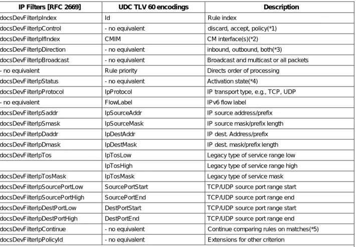
Table C–2 - Mapping of docsDevFilterIpTable [RFC 2669] to UDCs for Layer 3 & 4 Criteria ... 136
Table C–3 - Upstream Drop Classification Values for LLC/MAC Classification ... 137
Table D–1 - Event Format and Content ... 141
Table E–4 - CmSymbolCapture Object ... 166
Table E–5 - CM Symbol Capture File Format ... 167
Table E–6 - CmOfdmChanEstimateCoef Object ... 169
Table E–7 - Channel Estimate Coefficient File Format ... 170
Table E–8 - CmDsConstDispMeas Object ... 171
Table E–9 - Constellation Display File Format ... 172
Table E–10 - CmDsOfdmRxMer Object ... 173
Table E–11 - RxMER File Format ... 174
Table E–12 - CmDsOfdmSnrMarForProfile Object ... 174
Table E–13 - CmDsOfdmRequiredQamMer Object ... 176
Table E–14 - CmDsHist Object ... 177
Table E–15 - Histogram Bin Centers ... 179
Table E–16 - Downstream Histogram File Format ... 180
Table E–17 - CmUsEq Object ... 180
Table E–18 - Upstream Equalization File Format ... 182
Table E–19 - Last EQ Update File Format ... 182
Table E–20 - CmBulkDataControl Object ... 184
Table E–21 - CmBulkDataFile Object ... 185
Table F–1 - General Data Types ... 188
Table F–2 - Extended Data Types ... 189
Table G–1 - Data Type Definitions ... 190
Table G–2 - Pre-3.0 DOCSIS and DOCSIS 3.0/3.1 CM Registration status mapping ... 192
Table G–3 - CmStatus Object ... 195
Table G–4 - CmStatusUs Object ... 197
Table G–5 - CmStatusUs Object ... 198
Table G–6 - CmCapabilities Object... 199
Table G–7 - CmDpvStats Object ... 200
Table G–8 - CmEventCtrl Object ... 201
Table G–9 - CmEm1x1Stats Object ... 201
Table G–10 - CmEmDlsStats Object ... 202
Table G–11 - CmEmDlsStatus Object ... 203
Table G–12 - CmSystemCfgState Object ... 204
Table G–13 - CM Downstream Parameter Data Types ... 205
Table G–14 - CM Downstream Parameter Data Types ... 207
Table G–15 - ScQamDownstreamChannel Object Attributes ... 208
Table G–16 - ScQamDownstreamChannel Object Associations ... 209
Table G–17 - DsOfdmChannel Object Attributes ... 210
Table G–18 - DsOfdmChannel Object Associations ... 211
Table G–19 - DsOfdmProfileStats Object Attributes ... 212
Table G–20 - DsOfdmProfileStats Object Associations ... 213
Table G–21 - DsOfdmSubcarrierState object Attributes ... 213
Table G–22 - DsOfdmChannelPower Object Attributes ... 214
Table G–23 - DsOfdmChannelPower Object Attributes ... 214
Table G–25 - Data Types ... 216
Table G–26 - ScQamUpstream Object Attributes ... 217
Table G–27 - ScQamUpstream Object Associations ... 218
Table G–28 - UsChExt Object ... 220
Table G–29 - UsOfdmaChannel Object Attributes ... 220
Table G–30 - UsOfdmaChannel Object Associations ... 221
Table G–31 - UsOfdmaProfile Object Attributes ... 222
Table G–32 - UsOfdmaProfile Object Associations ... 222
Table G–33 - UsOfdmaSubcarrierCfgState Object Attributes... 222
Table G–34 - UsOfdmaMinislotCfgState Object Attributes ... 223
Table H–1 - Data Type Definitions ... 224
Table H–2 - RxModuleStatus Object... 227
Table H–3 - RxChStatus Object ... 228
Table H–4 - PktClass Object ... 231
Table H–5 - ParamSet Object ... 237
Table H–6 - ServiceFlow Object ... 247
Table H–7 - ServiceFlowSidCluster Object ... 249
Table H–8 - ServiceFlowStats Object ... 251
Table H–9 - DynamicServiceStats Object ... 253
Table H–10 - CmServiceUsStats Object ... 258
Table H–11 - CmDsid Object ... 261
Table H–12 - CmDsidStats Object ... 262
Table H–13 - CmDsidClient Object ... 263
Table H–14 - CmMdCfg Object ... 264
Table H–15 - CmEnergyMgt1x1Cfg Object... 265
Table H–16 - CmEnergyMgtDlsCfg Object ... 266
Table H–17 - CmMac Object ... 267
Table I–1 - RF Management Statistics Available ... 268
Table II–1 - ObjectA Example Table Layout ... 273
1 SCOPE
1.1 Introduction and Purpose
This specification is part of the DOCSIS® family of specifications developed by Cable Television Laboratories (CableLabs®). In particular, this specification is part of a series of specifications that define the fourth generation of high-speed data-over-cable systems. This specification was developed for the benefit of the cable industry, and includes contributions by operators and vendors from North America, Europe, and other regions.
This specification defines the Operations Support System Interface (OSSI) requirements for the Cable Modem (CM).
1.2 Background
1.2.1 Broadband Access Network
A coaxial-based broadband access network is assumed. This may take the form of either an all-coax or hybrid-fiber/coax (HFC) network. The generic term "cable network" is used here to cover all cases.
A cable network uses a tree-and-branch architecture with analog transmission. The key functional characteristics assumed in this document are the following:
• Two-way transmission.
• A maximum optical/electrical spacing between the CMTS and the most distant CM of 100 miles in each direction, although typical maximum separation may be 10-15 miles.
• A maximum differential optical/electrical spacing between the CMTS and the closest and most distant modems of 100 miles in each direction, although this would typically be limited to 15 miles.
At a propagation velocity in fiber of approximately 1.5 ns/ft., 100 miles of fiber in each direction results in a round-trip delay of approximately 1.6 ms.
1.2.2 Network and System Architecture
1.2.2.1 The DOCSIS Network
The elements that participate in the provisioning of DOCSIS services are shown in Figure 1–1.
Figure 1–1 - The DOCSIS Network
The CM connects to the operator's HFC network and to a home network, bridging packets between them. Many CPE devices can connect to the CM's LAN interfaces. CPE devices can be embedded with the CM in a single device, or they can be separate standalone devices (as shown in Figure 1–1). CPE devices may use IPv4, IPv6 or both forms of IP addressing. Examples of typical CPE devices are home routers, set-top devices, and personal computers. The CMTS connects the operator's back office and core network with the HFC network. Its main function is to forward packets between these two domains, and optionally to forward packets between upstream and downstream channels on the HFC network. The CMTS performs this forwarding with any combination of link-layer (bridging) and network-layer (routing) semantics.
Various applications are used to provide back office configuration and other support to the devices on the DOCSIS network. These applications use IPv4 and/or IPv6 as appropriate to the particular operator's deployment. The following applications include:
• Provisioning Systems
• The DHCP servers provide the CM with initial configuration information, including the device IP address(es), when the CM boots.
• The Configuration File server is used to download configuration files to CMs when they boot. Configuration files are in binary format and permit the configuration of the CM's parameters. The Software Download server is used to download software upgrades to the CM.
• The Time Protocol server provides Time Protocol clients, typically CMs, with the current time of day.
• Network Management System (NMS)
• The SNMP Manager allows the operator to configure and monitor SNMP Agents which reside within the
Provisioning Systems IPv6 CPE IPv4 CPE
Back Office Network HFC Network Home Network
CMTS CM IPv6 CPE IPv4 CPE CM NMS HFC
1.2.3 Service Goals
As cable operators have widely deployed high-speed data services on cable television systems, the demand for bandwidth has increased. Additionally, networks have scaled to such a degree that IPv4 address constraints are becoming a burden on network operations. To this end, CableLabs' member companies have decided to add new features to the DOCSIS® specification for the purpose of increasing channel capacity, enhancing network security, expanding addressability of network elements, and deploying new service offerings.
The DOCSIS system allows transparent bi-directional transfer of Internet Protocol (IP) traffic, between the cable system headend and customer locations, over an all-coaxial or hybrid-fiber/coax (HFC) cable network. This is shown in simplified form in Figure 1–2.
Figure 1–2 - Transparent IP Traffic through the Data-Over-Cable System
1.2.4 Statement of Compatibility
This specification defines the DOCSIS 3.1 interface. Prior generations of DOCSIS were commonly referred to as DOCSIS 1.0, 1.1, 2.0 and 3.0 interfaces. DOCSIS 3.1 is backward-compatible with equipment built to the previous specifications with the exception of DOCSIS 1.0 CMs. DOCSIS 3.1-compliant CMs interoperate seamlessly with DOCSIS 3.1 and DOCSIS 3.0 CMTSs. DOCSIS 3.1-compliant CMTSs seamlessly support DOCSIS 3.0, DOCSIS 2.0, and DOCSIS 1.1.
1.2.5 Reference Architecture
Figure 1–3 - Data-over-Cable Reference Architecture
The reference architecture for data-over-cable services and interfaces is shown in Figure 1–3.
1.2.6 DOCSIS 3.1 Documents
A list of the specifications in the DOCSIS 3.1 series is provided in Table 1–1. For further information, please refer
to http://www.cablemodem.com.
Table 1–1 - DOCSIS 3.1 Series of Specifications
Designation Title
CM-SP-PHYv3.1 Physical Layer Specification
CM-SP-MULPIv3.1 Media Access Control and Upper Layer Protocols Interface Specification
CM-SP-CM-OSSIv3.1 Cable Modem Operations Support System Interface Specification
CM-SP-CCAP-OSSIv3.1 Converged Cable Access Platform Operations Support System Interface Specification
CM-SP-SECv3.0 Security Specification
CM-SP-CMCIv3.0 Cable Modem CPE Interface Specification
This specification is defining the interface for the Operations Support Systems Interface (OSSI), specifically for the Cable Modem.
Related DOCSIS specifications are listed in Table 1–2.
Table 1–2 - DOCSIS 3.1 Related Specifications
Designation Title Rx Rx Tx Tx Fiber Node Fiber Node M-CMTS Core EQAM Upstream Receiver DOCSIS Timing Server Wide Area Network Network Side Interface (NSI)
Operations Support System Interface (OSSI) Cable Modem to CPE Interface (CMCI) Downstream External Phy Interface (DEPI) DOCSIS Timing Interface (DTI) Downstream RF Interface ( DRFI) Cable Modem (CM) Operations Support System
Physical Layer Interface (PHY) Downstream RF Network Upstream RF Network Opt. Tx Opt. Rx Fiber Node M-CMTS I-CMTS / CCAP
Distribution Hub or Headend
Coax Distribution Fiber
Distribution
NOTE: Gray-shaded areas represent related functionality, but are out of scope of this document.
MAC & Upper Layer Protocols Interface (MULPI)
& Security Interface (SEC)
Customer Premises Equipment
Designation Title CM-SP-DRFI Downstream Radio Frequency Interface Specification
CM-SP-DTI DOCSIS Timing Interface Specification
CM-SP-DEPI Downstream External PHY Interface Specification
CM-SP-DSG DOCSIS Set-Top Gateway Interface Specification
CM-SP-ERMI Edge Resource Manager Interface Specification
CM-SP-M-OSSI M-CMTS Operations Support System Interface Specification
CM-SP-L2VPN Layer 2 Virtual Private Networks Specification
CM-SP-TEI TDM Emulation Interface Specification
1.3 Requirements
Throughout this document, the words that are used to define the significance of particular requirements are capitalized. These words are:
"MUST" This word means that the item is an absolute requirement of this specification. "MUST NOT" This phrase means that the item is an absolute prohibition of this specification.
"SHOULD" This word means that there may exist valid reasons in particular circumstances to ignore this item, but the full implications should be understood and the case carefully weighed before choosing a different course.
"SHOULD NOT" This phrase means that there may exist valid reasons in particular circumstances when the listed behavior is acceptable or even useful, but the full implications should be understood and the case carefully weighed before implementing any behavior described with this label.
"MAY" This word means that this item is truly optional.One vendor may choose to include the item because a particular marketplace requires it or because it enhances the product, for example; another vendor may omit the same item.
This document defines many features and parameters, and a valid range for each parameter is usually specified. Equipment (CM) requirements are always explicitly stated. Equipment must comply with all mandatory (MUST and MUST NOT) requirements to be considered compliant with this specification. Support of non-mandatory features and parameter values is optional.
1.4 Conventions
In this specification the following convention applies any time a bit field is displayed in a figure. The bit field should be interpreted by reading the figure from left to right, then from top to bottom, with the MSB being the first bit so read and the LSB being the last bit so read.
SNMP MIB syntax is represented by this code sample font. Note: Notices and/or Warnings are identified by this style font and label.
1.5 Organization of Document
Section 1 provides an overview of the DOCSIS 3.1 series of specifications including the DOCSIS reference architecture and statement of compatibility.
Section 2 includes a list of normative and informative references used within this specification. Section 3 defines the terms used throughout this specification.
Section 4 defines the acronyms used throughout this specification.
Section 5 provides a technical overview and lists the DOCSIS 3.1 key features for the functional areas of this specification.
Section 6 defines requirements for the OSSI management protocols.
Section 7 defines the requirements for the OSSI management objects including SNMP MIBs. Section 8 defines the FCAPS OSSI requirements for the PHY, MAC, and Network Layers. Section 9 defines the OSSI requirements for the Cable Modem to CPE Interface (CMCI).
Section 10 defines the OSSI requirements for the Cable Modem device including LED operations.
1.5.1 Annexes (Normative)
Annex A includes a detailed list of MIB object requirements for the CM. Annex B defines the IETF multicast MIB requirements.
Annex C defines protocol filtering requirements.
Annex D includes a detailed list of DOCSIS events and the associated formats.
Annex E defines the information model for the DOCSIS 3.1 Enhanced Signal Quality Monitoring feature. Annex F defines the DOCSIS 3.1 data type definitions.
Annex G defines the information model for the CM status and interface requirements. Annex H defines the information model for the CM MULPI requirements.
1.5.2 Appendices (Informative)
Appendix I identifies spectrum analysis use cases.
Appendix II provides an overview of the Information Model Notation using UML. Appendix III includes acknowledgements and contains a list of contributors.
2 REFERENCES
2.1 Normative References
In order to claim compliance with this specification, it is necessary to conform to the following standards and other works as indicated, in addition to the other requirements of this specification. Notwithstanding, intellectual property rights may be required to use or implement such normative references.
[CCAP-OSSIv3.1]
DOCSIS Converged Cable Access Platform Operations Support System Interface Specification, CM-SP-CCAP-OSSIv3.1-I01-140808, August 8, 2014, Cable Television Laboratories, Inc. [CMCIv3.0] DOCSIS Cable Modem to Customer Premise Equipment Interface Specification,
CM-SP-CMCIv3.0-I02-140729, July 29, 2014, Cable Television Laboratories, Inc.
[DOCS-IFEXT2-MIB]
CableLabs DOCSIS DOCS-IFEXT2-MIB SNMP MIB Module, DOCS-IFEXT2-MIB,
http://www.cablelabs.com/MIBs/DOCSIS/.
[DOCS-IF3-MIB]
CableLabs DOCSIS DOCS-IF3-MIB SNMP MIB Module, DOCS-IF3-MIB,
http://www.cablelabs.com/MIBs/DOCSIS/.
[DOCS-QOS3-MIB]
CableLabs DOCSIS DOCS-QOS3-MIB SNMP MIB Module, DOCS-QOS3-MIB,
http://www.cablelabs.com/MIBs/DOCSIS/.
[DSG] DOCSIS Set-Top Gateway (DSG) Interface Specification, CM-SP-DSG-I24-130808, August 8, 2013, Cable Television Laboratories, Inc.
[IPDR/SSDG] IPDR Service Specification Design Guide, Version 3.8, TM Forum, October 2009. [IPDR/XDR] IPDR/XDR File Encoding Format, Version 3.5.1, TM Forum, October 2009.
[M-OSSI] DOCSIS M-CMTS Operations Support System Interface Specification, CM-SP-M-OSSI-I08-081209, December 9, 2008, Cable Television Laboratories, Inc.
[MULPIv3.1] DOCSIS MAC and Upper Layer Protocols Interface Specification, CM-SP-MULPIv3.1-I03-140610, June 10, 2014, Cable Television Laboratories, Inc.
[PHYv3.1] DOCSIS Physical Layer Specification, CM-SP-PHYv3.1-I03-140610, June 10, 2014, Cable Television Laboratories, Inc.
[RFC 1157] IETF RFC 1157, J. D. Case, et al., A Simple Network Management Protocol (SNMP), May 1990.
[RFC 1901] IETF RFC 1901, K. Norseth, Ed. and E. Bell, Ed., Introduction to Community-based SNMPv2, January 1996.
[RFC 2578] IETF RFC 2578, K. McCloghrie, et al., Structure of Management Information Version 2 (SMIv2), April 1999.
[RFC 2580] IETF RFC 2580, K. McCloghrie, et al., Conformance Statements for SMIv2, April 1999. [RFC 2669] IETF RFC 2669, M. St. Johns, Ed., DOCSIS Cable Device MIB Cable Device Management
Information Base for DOCSIS compliant Cable Modems and Cable Modem Termination Systems, August 1999.
[RFC 2786] IETF RFC 2786, M. St. Johns, Diffie-Helman [sic] USM Key Management Information Base and Textual Convention, March 2000.
[RFC 2790] IETF RFC 2790, Waldbusser, P. Grillo, Host Resources MIB, March 2000.
[RFC 2863] IETF RFC 2863, K. McCloghrie and F. Kastenholz, The Interfaces Group MIB, June 2000. [RFC 2933] IETF RFC 2933, K. McCloghrie et al., Internet Group Management Protocol MIB, October
2000.
[RFC 3083] IETF RFC 3083, R. Woundy, Baseline Privacy Interface Management Information Base for DOCSIS Compliant Cable Modems and Cable Modem Termination Systems, March 2001. [RFC 3164] IETF RFC 3164, C. Lonvick, The BSD syslog Protocol, August 2001.
[RFC 3410] IETF RFC 3410, J. Case, et al., Introduction and Applicability Statements for Internet-Standard Management Framework, December 2002.
[RFC 3411] IETF RFC 3411/STD0062, D. Harrington, et al., An Architecture for Describing Simple Network Management Protocol (SNMP) Management Frameworks, December 2002. [RFC 3412] IETF RFC 3412, J. Case, et al., Message Processing and Dispatching for the Simple Network
Management Protocol (SNMP), December 2002.
[RFC 3413] IETF RFC 3413/STD0062, D. Levi, et al., Simple Network Management Protocol (SNMP) Applications, December 2002.
[RFC 3414] IETF RFC 3414/STD0062, U. Blumenthal and B. Wijnen, User-based Security Model (USM) for version 3 of the Simple Network Management Protocol (SNMPv3), December 2002. [RFC 3415] IETF RFC 3415, B. Wijnen, et al., View-based Access Control Model (VACM) for the Simple
Network Management Protocol (SNMP), December 2002.
[RFC 3416] IETF RFC 3416, R. Presuhn, Ed., Version 2 of the Protocol Operations for the Simple Network Management Protocol (SNMP), December 2002.
[RFC 3417] IETF RFC 3417, R. Presuhn, Ed., Transport Mappings for the Simple Network Management Protocol (SNMP), December 2002.
[RFC 3418] IETF RFC 3418, R. Presuhn, Ed., Management Information Base (MIB) for the Simple Network Management Protocol (SNMP), December 2002.
[RFC 3419] IETF RFC 3419, M. Daniele, J. Schoenwaelder, Textual Conventions for Transport Addresses, December 2002.
[RFC 3433] IETF RFC 3433, A. Bierman, D. Romascanu, K.C. Norseth, Entity Sensor Management Information Base, December 2002.
[RFC 3584] IETF RFC 3584, R. Frye, et al., Coexistence between Version 1, Version 2, and Version 3 of the Internet-Standard and Network Management Framework, March 2000.
[RFC 3635] IETF RFC 3635, J. Flick, Definitions of Managed Objects for the Ethernet-like Interface Types, September 2003.
[RFC 3826] IETF RFC 3826, U. Blumenthal, et al., The Advanced Encryption Standard (AES) Cipher Algorithm in the SNMP User-based Security Model, June 2004.
[RFC 3927] IETF RFC 3927, G. Klyne, et al., Dynamic Configuration of IPv4 Link-Local Addresses, May 2005.
[RFC 4022] IETF RFC 4022, R. Raghunarayan, Ed., Management Information Base for the Transmission Control Protocol (TCP), March 2005.
[RFC 4113] IETF RFC 4113, B. Fenner and J. Flick, Management Information Base for the User Datagram Protocol (UDP), June 2005.
[RFC 4131] IETF RFC 4131, S. Green et al., Management Information Base for Data Over Cable Service Interface Specification (DOCSIS) Cable Modems and Cable Modem Termination Systems for Baseline Privacy Plus, September 2005.
[RFC 4133] IETF RFC 4133, A. Bierman, K. and McCloghrie, Entity MIB, August 2005.
[RFC 4188] IETF RFC 4188, K. Norseth, Ed. and E. Bell, Ed., Definitions of Managed Objects for Bridges, September 2005.
[RFC 4293] IETF RFC 4293, S. Routhier, Ed., Management Information Base for the Internet Protocol (IP), April 2006.
[RFC 4546] IETF RFC 4546, D. Raftus and E. Cardona, Radio Frequency (RF) Interface Management Information Base for DOCSIS 2.0 Compliant RF Interfaces, June 2006.
[RFC 4639] IETF RFC 4639, R. Woundy and K. Marez, Cable Device Management Information Base for Data-Over-Cable Service Interface Specification (DOCSIS) Compliant Cable Modems and
[SECv3.0] DOCSIS Security Specification, CM-SP-SECv3.0-I15-130808, August 8, 2013, Cable Television Laboratories, Inc.
[USB] Universal Serial Bus Specification, Compaq, Hewlett-Packard, Intel, Lucent, Microsoft, NEC, Philips, Revision 2.0, April 27, 2000 (http://www.usb.org)
2.2 Informative References
This specification uses the following informative references.
[ISO 11404] ISO/IEC 11404:1996 Information technology--Programming languages, their environments and system software interfaces--Language-independent datatypes, January 2002.
[ISO 19501] ISO/IEC 19501:2005 Information technology -- Open Distributed Processing -- Unified Modeling Language (UML) Version 1.4.2.
[ITU-T X.692] ITU-T Recommendation X.692 (03/2002), Information technology – ASN.1 encoding rules: Specification of Encoding Control Notation (ECN).
[ITU-T M.3400] ITU-T Recommendation M.3400 (02/2000), TMN management functions. [RFC 791] IETF RFC 791, J. Postel. Internet Protocol, September 1981.
[RFC 1213] IETF RFC 1213, K. McCloghrie and M. Rose, Management Information Base for Network Management of TCP/IP-based internets: MIB-II, March 1991.
[RFC 1350] IETF RFC 1350, K. Sollins, TFTP Protocol (Revision 2), July 1992.
[RFC 2460] IETF RFC 2460, Internet Protocol, Version 6 (IPv6) Specification. S. Deering and R. Hinden, December 1998.
[RFC 2579] IETF RFC 2579, K. McCloghrie, et al., Textual Conventions for SMIv2, April 1999. [RFC 2856] IETF RFC 2856, A. Bierman, et al., Textual Conventions for Additional High Capacity Data
Types, June 2000.
[RFC 3168] IETF RFC 3168, K. Ramakrishnan et al., The Addition of Explicit Congestion Notification. [RFC 3260] IETF RFC 3260, D. Grossman, New Terminology and Clarifications for Diffserv, April 2002. [RFC 3289] IETF RFC 3289, F. Baker, K. Chan, A. Smith, Management Information Base for the
Differentiated Services Architecture, May 2002.
[RFC 4001] IETF RFC 4001, M. Daniele, et al., Textual Conventions for Internet Network Addresses, February 2005.
[RFC 4181] IETF RFC 4181, C. Heard, Ed. Guidelines for Authors and Reviewers of MIB Documents, September 2005.
[RFC 4291] IETF RFC 4291, R. Hinden and S. Deering, Internet Protocol Version 6 (IPv6) Addressing Architecture, February 2006.
[SCTE RP] SCTE Measurement Recommended Practices for Cable Systems, Fourth Edition, March 2012,
https://www.scte.org/devams/cgi-bin/msascartlist.dll/ProductInfo?productcd=TS46
2.3 Reference Acquisition
CableLabs Specifications:
• Cable Television Laboratories, Inc., 858 Coal Creek Circle, Louisville, CO 80027; Phone +1-303-661-9100, Fax +1-303-661-9199; http://www.cablelabs.com ANSI Specifications:
• American National Standards Institute, Inc. 1819 L Street, NW, 6th floor
IETF Specifications:
• Internet Engineering Task Force (IETF) Secretariat, 48377 Fremont Blvd., Suite 117, Fremont, California 94538, USA; Phone: +1-510-492-4080, Fax: +1-510-492-4001.
ISO Specifications:
• International Organization for Standardization (ISO), 1, rue de Varembé, Case postale 56, CH-1211 Geneva 20, Switzerland; Phone +41 22 749 01 11, Fax +41 22 733 34 30; http://www.iso.org
ITU Recommendations:
• International Telecommunication Union, Place des Nations, CH-1211, Geneva 20, Switzerland; Phone +41-22-730-51-11; Fax +41-22-733-7256; http://www.itu.int
TM Forum:
• 240 Headquarters Plaza, East Tower, 10th Floor, Morristown, NJ 07960-6628; Phone: +1 973-944-5100, Fax: +1 973-944-5110; http://www.tmforum.org/DownloadCenter/7549/home.html#ipdr
3 TERMS AND DEFINITIONS
This specification uses the following terms:Active Queue Management
AQM schemes attempt to maintain low queue occupancy (within Downstream and Upstream service flows) while supporting the ability to absorb a momentary traffic burst.
Allocation A group of contiguous mini-slots in a MAP which constitute a single transmit opportunity.
Burst A single continuous RF signal from the upstream transmitter, from transmitter on to transmitter off.
Cable Modem (CM) A modulator-demodulator at subscriber locations intended for use in conveying data communications on a cable television system.
Cable Modem Termination System (CMTS)
Cable modem termination system, located at the cable television system headend or distribution hub, which provides complementary functionality to the cable modems to enable data connectivity to a wide-area network.
Cable Modem to CPE Interface (CMCI)
The interface, defined in [CMCIv3.0], between a CM and CPE.
Carrier-to-Noise plus Interference Ratio (CNIR)
The ratio of the expected commanded received signal power at the CMTS input to the noise plus interference in the channel.
Channel The frequency spectrum occupied by a signal. Usually specified by center frequency and bandwidth parameters.
Classifier A set of criteria used for packet matching according to TCP, UDP, IP, LLC, and/or 802.1P/Q packet fields. A classifier maps each packet to a Service Flow. A
Downstream Classifier is used by the CMTS to assign packets to downstream service flows. An Upstream Classifier is used by the CM to assign packets to upstream service flows.
Customer See End User.
Customer Premises Equipment (CPE)
Equipment at the end user's premises; may be provided by the end user or the service provider.
Data Model A Data Model (as opposed to an Information Model) is defined at a lower level of abstraction, intended for implementations, and includes protocol-specific constructs. Since conceptual models can be implemented in different ways, multiple Data Models can be derived from a single Information Model. Data Models are technology specific. The Cable Modem has defined Data Models for SNMP as SNMP MIB modules.
Downstream (DS) In cable television, the direction of transmission from the headend to the subscriber.
End User A human being, organization, or telecommunications system that accesses the network in order to communicate via the services provided by the network.
FCAPS A set of principles for managing networks and systems, wherein each letter represents one principle. F is for Fault, C is for Configuration, A is for Accounting, P is for Performance, S is for Security.
Fiber Node A point of interface between a fiber trunk and the coaxial distribution.
Hybrid Fiber/Coax (HFC) System
A broadband bidirectional shared-media transmission system using fiber trunks between the headend and the fiber nodes, and coaxial distribution from the fiber nodes to the customer locations.
Inform A confirmed SNMP message for asynchronous notification of events from an SNMP entity.
Information Model An Information Model (as opposed to a Data Model) is an abstraction and only provides a high level view of things of interest (i.e., information) to the business. It aids in understanding the scope and breadth of the business, rather than the depth. An Information Model is a way of representing and structuring information that has advantages over other common artifacts such as a glossary, descriptive document, database or source code. A common Information Model will streamline the processes associated with information exchange, both within a business (e.g., Enterprise) and between the business and its external stakeholders.
International Organization for Standardization (ISO)
An international standards body, commonly known as the International Standards Organization.
Local Log A volatile or non-volatile log stored within a network element.
Logical Upstream Channel
A MAC entity identified by a unique channel ID and for which bandwidth is allocated by an associated MAP message. A physical upstream channel may support multiple logical upstream channels. The associated UCD and MAP messages completely describe the logical channel.
Media Access Control (MAC) address
The "built-in" hardware address of a device connected to a shared medium.
MAC Domain A subcomponent of the CMTS that provides data forwarding services to a set of downstream and upstream channels.
MAC Domain Downstream Service Group
The subset of a Downstream Service Group (DS-SG) which is confined to the Downstream Channels of a single MAC domain. An MD-SG differs from a DS-SG only when multiple MAC domains are configured per CM-DS-SG.
MAC Domain Upstream Service Group
The subset of an Upstream Service Group (US-SG) which is confined to the Upstream Channels of a single MAC Domain. An MD-US-SG differs from a US-SG only when multiple MAC domains are defined per CM-SG.
Micro-reflections Echoes in the forward or reverse transmission path due to impedance mismatches between the physical plant components. Micro-reflections are distinguished from discrete echoes by having a time difference (between the main signal and the echo) on the order of 1 microsecond. Micro-reflections cause departures from ideal amplitude and phase characteristics for the transmission channel.
Mini-Slot A "mini-slot" is an integer multiple of 6.25-microsecond increments.
Network Management The functions related to the management of data link layer and physical layer
resources and their stations across the data network supported by the hybrid fiber/coax system.
Network Management System (NMS)
The hardware and software components used by the Network Provider to manage its networks as a whole. The Network Management System provides an end-to-end network view of the entire network enabling management of the network elements contained in the network.
Notification Information emitted by a managed object relating to an event that has occurred within the managed object.
Open Systems
Interconnection (OSI)
A framework of ISO standards for communication between different systems made by different vendors, in which the communications process is organized into seven different categories that are placed in a layered sequence based on their relationship to the user. Each layer uses the layer immediately below it and provides a service to the layer above. Layers 7 through 4 deal with end-to-end communication between the message source and destination, and layers 3 through 1 deal with network functions.
Physical (PHY) Layer Layer 1 in the Open System Interconnection (OSI) architecture; the layer that provides services to transmit bits or groups of bits over a transmission link between open
Pre-3.0 DOCSIS Versions of CableLabs Data-Over-Cable-Service-Interface-Specifications (DOCSIS) prior to the DOCSIS 3.0 suite of specifications.
Primary Service Flow All CMs have a Primary Upstream Service Flow and a Primary Downstream Service Flow. They ensure that the CM is always manageable and they provide a default path for forwarded packets that are not classified to any other Service Flow.
Proactive Network Maintenance
The process and mechanism of measuring and assessing network conditions of the cable plant to determine error or fault conditions before becoming service impacting.
QoS Parameter Set The set of Service Flow Encodings that describe the Quality of Service attributes of a Service Flow or a Service Class.
Service Class A set of queuing and scheduling attributes that is named and that is configured at the CMTS. A Service Class is identified by a Service Class Name. A Service Class has an associated QoS Parameter Set.
Service Class Name An ASCII string by which a Service Class may be referenced in modem configuration files and protocol exchanges.
Service Flow A MAC-layer transport service which provides unidirectional transport of packets from the upper layer service entity to the RF and shapes, polices, and prioritizes traffic according to QoS traffic parameters defined for the Flow.
Service Flow Identifier (SFID)
A 32-bit identifier assigned to a service flow by the CMTS.
Service Identifier (SID) An 14-bit identifier assigned by the CMTS to an Active or Admitted Upstream Service Flow.
Simple Network Management Protocol (SNMP)
A network management protocol of the IETF.
SNMP Agent The term "agent" is used throughout this document to refer to 1) a SNMPv1/v2 agent or 2) a SNMPv3 entity [RFC 3411] which contains command responder and
notification originator applications.
SNMP Manager The term "manager" is used throughout this document to refer to 1) a SNMPv1/v2 manager or 2) a SNMPv3 entity [RFC 3411] which contains command generator and/or notification receiver applications.
Subscriber See End User.
Syslog A protocol that provides the transport of event notifications messages across IP networks.
Trap An unconfirmed SNMP message for asynchronous notification of events from an SNMP entity.
4 ABBREVIATIONS AND ACRONYMS
This specification uses the following abbreviations:ACK Acknowledge
ANSI American National Standards Institute
AQM Active Queue Management
ARP Address Resolution Protocol
ASCII American Standard Code for Information Interchange
ASN.1 Abstract Syntax Notation 1
BOOTR Boot ROM
BPI Baseline Privacy Interface
BPI+ Baseline Privacy Interface Plus
BPKM Baseline Privacy Key Management
BSS Business Support System
CableLabs Cable Television Laboratories Inc.
CATV Community Access Television, Cable Television
CDC Communications Device Class
CLI Command Line Interface
CM Cable Modem
CMCI Cable Modem to CPE Interface
CMIM Cable Modem Interface Mask
CM-SG Cable Modem Service Group
CMTS Cable Modem Termination System
CNIR Carrier-to-Noise plus Interference Ratio
CoS Class of Service
CPE Customer Premises Equipment
CPU Central Processing Unit
CSR Customer Service Representative
CVC Code Verification Certificate
dB Decibel
DBC Dynamic Bonding Change
DBG Downstream Bonding Group
DCC Dynamic Channel Change
DCID Downstream Channel Identifier
DEPI Downstream External Physical layer Interface
DFT Discrete Fourier Transform
DH Diffie-Hellman
DHCP Dynamic Host Configuration Protocol
DS Downstream
DSAP Destination Service Access Point
DSCP Differentiated Services Code Point
DSID Downstream Service Identifier
DTD Document Type Definition
EAE Early Authentication and Encryption
ERMI Edge Resource Manager Interface
eSAFE Embedded Service/Application Functional Entity
EUI-64 64-bit Extended Unique Identifier
FC Frame Control
FCAPS Fault, Configuration, Accounting, Performance, Security
FEC Forward Error Correction
FFT Fast Fourier Transform
FSM Finite State Machine
GMAC Group Media Access Control
HFC Hybrid Fiber/Coax (HFC) System
HMAC Keyed-Hash Message Authentication Code
IANA Internet Assigned Numbers Authority
ICMP Internet Control Message Protocol
ID Identifier
IEEE Institute of Electrical and Electronics Engineers
IETF Internet Engineering Task Force
IGMP Internet Group Management Protocol
IM Information model
INIT Initialize or Initialization
IP Internet Protocol
IPv4 Internet Protocol version 4
IPv6 Internet Protocol version 6
IPDR Internet Protocol Detail Record
ISO International Standards Organization
ITU International Telecommunications Union
ITU-T Telecommunication Standardization Sector of the International Telecommunication Union
LAN Local Area Network
LED Light Emitting Diode
LLC Logical Link Control
LSB Least Significant Bit
MAC Media Access Control
MAP Bandwidth Allocation Map
M-CMTS Modular Cable Modem Termination System
MDD MAC Domain Descriptor
MD-US-SG MAC Domain Upstream Service Group
MDF Multicast DSID Forwarding
MER Modulation Error Ratio
MGMD Multicast Group Membership Discovery
MIB Management Information Base
MP Multipart
MSB Most Significant Bit
MSO Multiple Systems Operator
MTA Multimedia Terminal Adapter
MTC Multiple Transmit Channel
MULPI MAC and Upper Layer Protocols Interface
NACO Network Access Control Object
NE Network Element
NMS Network Management System
NSI Network Side Interface
OID Object Identifier
OFDM Orthogonal Frequency Division Multiplexing
OFDMA Orthogonal Frequency Division Multiple Access
OSI Open Systems Interconnection
OSS Operations Support System
OSSI Operations Support System Interface
PC Personal Computer
PCMM PacketCable™ Multimedia
PDU Protocol Data Unit
PHY Physical Layer
PIE Proportional Integral controller Enhanced
PNM Proactive Network Maintenance
QAM Quadrature Amplitude Modulation
QoS Quality of Service
PHS Payload Header Suppression
QPSK Quadrature Phase-Shift Keying
RCC Receive Channel Configuration
RCP Receive Channel Profile
RCP-ID Receive Channel Profile Identifier
RCS Receive Channel Set
REG Registration
RFC Request for Comments
RF Radio Frequency
RFI Radio Frequency Interface
SA Security Association or Source Address
SAID Security Association Identifier
SAMIS Subscriber Accounting Management Interface Specification
S-CDMA Synchronous Code Division Multiple Access
SCN Service Class Name
SC-QAM Single Carrier Quadrature Amplitude Modulation
SF Service Flow
SFID Service Flow Identifier
SG Service Group
SID Service Identifier
SLA Service Level Agreement
SMI Structure of Management Information
SMIv1 Structure of Management Information Version 1
SMIv2 Structure of Management Information Version 2
SNAP Sub-network Access Protocol
SNMP Simple Network Management Protocol
SNMPv1 Version 1 of the Simple Network Management Protocol
SNMPv2 Version 2 of the Simple Network Management Protocol
SNMPv2c Community-Based Simple Network Management Protocol, version 2
SNMPv3 Version 3 of the Simple Network Management Protocol
SNR Signal to Noise Ratio
SP Streaming Protocol
SSD Secure Software Download
STP Spanning Tree Protocol
SW Software
SYNC Synchronize or Synchronization
TBD To Be Determined (or To Be Deferred)
TEK Traffic Encryption Key
TLV Type/Length/Value
TCP Transmission Control Protocol
TCS Transmit Channel Set
TFTP Trivial File Transfer Protocol
TOD Time Of Day
TOS Type of Service
UBG Upstream Bonding Group
UCC Upstream Channel Change
UCD Upstream Channel Descriptor
UCID Upstream Channel Identifier
UDC Upstream Drop Classifier
UDP User Datagram Protocol
US Upstream
USB Universal Serial Bus
USM User-based Security Model
VACM View-based Access Control Model
VLAN Virtual Local Area Network
XDR External Data Representation
XML Extensible Markup Language
5 OVERVIEW
This section provides a brief description of the key management features introduced in DOCSIS 3.1. These features are categorized according to the five conceptual categories of management developed as part of ITU
Recommendation [ITU-T M.3400]. This set of management categories is referred to as the FCAPS model, represented by the individual management categories of Fault, Configuration, Accounting, Performance and Security.
In addition to the description of features, the rationale behind the introduction of information models is presented. Section 5.1 discusses the requirements introduced in this specification for DOCSIS 3.1, and Section 5.2 is a technical introduction to the detailed models in support of the user requirements.
5.1 DOCSIS 3.1 OSSI Key Features
Table 5–1 summarizes the new requirements that support new DOCSIS 3.1 features and the enhancements to existing management features. The table shows the management features along with the traditional Network Management Functional areas (Fault, Configuration, Accounting, Performance and Security) for the Network Elements (NE) Cable Modem (CM) and the corresponding OSI layer where those features operate.
Table 5–1 - Management Feature Requirements for DOCSIS 3.1
Features Management
Functional Area
OSI layer Description
OFDM downstream signals and OFDMA upstream signals
Configuration PHY Provisioning physical downstream and upstream interfaces that support OFDM/OFDMA receivers according to their capabilities.
Plant Topology Configuration PHY, MAC (Data Link)
Provisioning flexible arrangements of US/DS channels for channel bonding configuration to reflect HFC plant topology.
Enhanced Diagnostics
Fault PHY, MAC, Network
Expanded metrics for Proactive Network Maintenance (PNM).
Enhanced Performance Data Collection
Performance PHY, MAC, Network
Collection of large statistical data sets for DOCSIS 3.1 feature sets.
Enhanced Signal Quality Monitoring
Performance PHY To gather information on narrow band ingress and distortion affecting the quality of the RF signals.
Light Sleep Mode Configuration MAC Energy efficiency mode for the Cable Modem to minimize power consumption. Backup Primary
Channels
Configuration MAC Retrieval of configuration status of backup downstream interfaces Active Queue
Management (AQM)
Configuration MAC Configuration of buffer management associated with service flows.
5.1.1 Fault Management Features
The DOCSIS 3.1 fault management requirements include:
• Expanded metrics for Proactive Network Maintenance (PNM).
5.1.2 Configuration Management Features
The configuration of the DOCSIS protocols for CM/CMTS interactions for configuring features in support of PHY MAC/QoS and Security (BPI) uses the CM configuration file and CMTS policies via MAC messages exchange. The reporting of configuration state information is done via SNMP MIB objects. This model provides a CM standard configuration with minimal operator intervention.
The DOCSIS 3.1 configuration requirements include:
• Updates to CM configuration parameters to support OFDM downstream interfaces, OFDMA upstream interfaces, light sleep mode and Active Queue Management (AQM).
• Retrieval of configuration status information for OFDM downstream interfaces, OFDMA upstream interfaces, light sleep mode, backup primary channels and Active Queue Management (AQM).
5.1.3 Performance Management Features
DOCSIS 3.1 requires an efficient mechanism for collecting large data sets as described above. The identified data sets are:
• Enhanced signal quality monitoring for granular plant status
• Statistics for dropped AQM packets
• Statistics for OFDM and OFMDA interface, subcarrier, profile and mini-slot counters
• Measurement Statistics for Proactive Network Maintenance (PNM)
5.1.4 Security Management Features
Security Management includes both security of management information (e.g., SNMP access control) and
management of network security related to authentication, authorization and privacy of data plane communications. There will be some small changes to the DOCSIS 3.1 Security Management feature set. Those changes are <TBD>.
5.1.5 Accounting Management Features
The DOCSIS 3.1 Accounting Management feature set is unchanged from DOCSIS 3.0.
5.2 Technical Overview
The technical overview presented in this section details functional areas of the FCAPS management model addressed by DOCSIS for managing the CM.
5.2.1 Architectural Overview
This section defines the functional areas of network management in terms of FCAPS (Fault, Configuration, Accounting, Performance and Security) as applied to the management of a CM within a DOCSIS network. The requirements in the previous section were grouped both according to the management functional area and the relevant DOCSIS layer (using the OSI reference model) where they apply. This section provides an overview of the functions supported by each area. Even though specific functions are described for each area, there are
interdependencies amongst all these functions to achieve the overall objective of efficient and proactive management of a CM in the DOCSIS network.
Fault management seeks to identify, isolate, correct and record system faults. Configuration management modifies system configuration variables and collects configuration information. Accounting management collects usage statistics for subscribers, sets usage quotas and bills users according to their use of the system. Performance
Figure 5–1 illustrates the CM management architecture from the MSO back office interface perspective. The CM and CMTS reside within the Network Layer where services are provided to end Subscribers and various metrics are collected about network and service performance, among other things. Various management servers reside in the Network Management Layer within the MSO back office to provision, monitor and administer the Network Elements within the Network Layer (CM in this case). These management servers include, but are not limited to:
• The SNMP Manager performs SNMP configuration and queries against a CM's SNMP Agent.
• The Configuration File Server has the responsibility of transferring configuration files, via TFTP or optionally HTTP to the CM upon reinitialization.
• The Firmware File Server has the responsibility of transferring firmware images, according to the Secure Software Download mechanism, to a CM.
• The Notification Receiver receives autonomous SNMP notifications and Syslog messages from a CM.
• The DHCP Server has the responsibility of assigning a CM its IPv4 and/or IPv6 address as well as other DHCP
parameters in order for the CM to obtain its configuration file and register on the network.
• The Time Server provides a CM with current Time of Day (ToD).
• The IPDR Collector Servers do not communicate directly with the CM. Rather, the CMTS collects various
CM-related statistics and communicates this information to the IPDR Collector servers.
• The TR-069 Server does not communicate directly with the CM. Rather, if the CM is an eDOCSIS device and
includes an eSAFE which supports the 069 protocol, the eDOCSIS device will communicate with the TR-069 server.
Figure 5–1 - CM Management Architecture
Finally, the Business and Service Management Layer is where higher level MSO business processes are implemented via BSS/OSS systems. These BSS/OSS systems utilize the data and information from the Network Management Layer which interrogated data from the Network Layer.
5.2.1.1 Fault Management
The goals of fault management are to provide failure detection, diagnosis, and perform or indicate necessary fault correction. Fault identification relies on the ability to monitor and detect problems, such as error-detection events. Fault resolution relies on the ability to diagnose and correct problems, such as executing a sequence of diagnostic test scripts, and correcting equipment or configuration faults. DOCSIS supports Event Reporting using Local Log, syslog and SNMP notifications.
5.2.1.2 Configuration Management
Configuration management is concerned with adding, initializing, maintaining and updating network elements. In a DOCSIS environment, network elements include CMs and CMTSs.
Configuration management is primarily concerned with network control via modifying operating parameters on network elements such as the CM and CMTS. Configuration parameters could include both physical resources (for example, an Ethernet interface) and logical objects (for example, QoS parameters for a given service flow). While the network is in operation, configuration management is responsible for monitoring the configuration state and making changes in response to commands by a management system or some other network management function.
For example, a performance management function may detect that response time is degrading due to a high number of uncorrected frames, and may issue a configuration management change to modify the modulation type from 16-QAM to QPSK. A fault management function may detect and isolate a fault and may issue a configuration change to mitigate or correct that fault.
5.2.1.3 Accounting Management
Accounting management, in general, includes collection of usage data and permits billing the customer based on the subscriber's use of network resources. The CMTS is the network element that is responsible for providing the usage statistics to support billing. Billing is outside the scope of this specification.
5.2.1.4 Performance Management
Performance management functions include collecting statistics of parameters such as number of frames lost at the MAC layer and number of codeword errors at the PHY layer. These monitoring functions are used to determine the health of the network and whether the offered Quality of Service (QoS) to the subscriber is met. The quality of signal at the PHY layer is an indication of plant conditions.
The previous versions of DOCSIS OSSI specification defines SNMP polling as the collection mechanism for CM and CMTS statistics for performance management. SNMP polling of CMs is scalable and widely deployed with specialized engines that minimize the upstream bandwidth allocated to management during the polling intervals.
5.2.1.5 Security Management
Security management is concerned with both security of management information to protect the MSOs operations systems as well as managing the security information. The latter is used to authenticate and secure the traffic on the HFC. Security of the management interface is required to prevent end users from accessing and initiating
configuration changes that may provide them with services for which they are not entitled or could result in the degradation or denial of services for other subscribers.
5.2.2 Management Protocols
As noted earlier in this section, the DOCSIS OSSI specification uses the Simple Network Management Protocol (SNMP) versions 1, 2c and 3 to define the management information for a CM DOCSIS network element in support of the functional areas mentioned in the previous section. SNMP is primarily a polling based protocol where the management system retrieves data such as counter values and state information. There are events defined as a notification that are used to inform the management systems of fault conditions and security violations. The support for SNMP versions is continued in DOCSIS 3.1.
5.2.3 Information Models
The approach is based on an object oriented modeling approach well known in the industry for capturing
requirements and analyzing the data in a protocol independent representation. This approach defines requirements with use cases to describe the interactions between the operations support systems and the network element. The management information is represented in terms of objects along with their attributes and the interactions between these encapsulated objects (or also referred to as entities in some representations). The diagrams developed to