SAF CFM-LM
Series Microwave Radio System Product
Family
Description
S O F T W A R E V E R S I O N 3 . 1 2
SAF Tehnika A/S 2003 Phone +371 7046840 • Fax +371 7020009
Table of Contents
C H A P T E R 1
Introduction 1 CFM Radio in the Modern Market 1 Typical Uses of the CFM Radio System 1 Abbreviations 1 C H A P T E R 2
CFM–LM Equipment 1 Overview 1 Main Features and Characteristics 1 Terminal and Site Configurations 1 C H A P T E R 3
Outdoor Unit and Antenna 1 General 1 Radio Unit 1 Frequency Channel Arrangement 1 Antenna Unit 1 C H A P T E R 4
Indoor Unit 1 General 1 IDU Functional Design 1 Update of Management Controller Software1 C H A P T E R 5
Cables 1
IDU–ODU Cable 1 Cable for Antenna Alignment 1 Traffic Interface Cables 1 Management Interface Cables 1 Power Cable 1
C H A P T E R 6
Management System 1 General, Main Goals 1 Management Features 1 Loop Tests 1 C H A P T E R 7 Accessories 1 Outdoor Accessories 1 Installation Tools 1 Earthing Accessories 1 Performance and Availability Calculations 1 Balancing Unit 1 C H A P T E R 8 Technical Data 1 General Parameters 1 Mechanical Data 1 Antenna Parameters 1 Power Supply 1 Environmental Requirements 1 References 1 SAF Tehnika A/S Contacts 1
Introduction
Proprietary notice
The specifications or information contained in this document are subject to change without notice due to continuing design improvement. If there is any conflict between this document and compliance statements, the latter will supersede this document.
The CFM LM series digital microwave radio system is equipment designed for the transmission of digital signals using radio waves in conditions within the line of sight. The type “LM” denotes the model of the Radio Unit (or Outdoor Unit – ODU). There are LM and L4 type ODUs that work with LM and L4 type Indoor Units correspondingly (Indoor Unit – IDU). This particular document describes the LM series microwave radio system which includes LM ODU and IDUs that work with the LM ODU.
The following LM type ODUs are available:
− CFM-22-LM, operates in 23 GHz band, WAN data rates: 8, 16, 34 Mbps,
− CFM-18-LM, operates in 18 GHz band, WAN data rates: 16, 34 Mbps,
− CFM-15-LM, operates in 15 GHz band, WAN data rates: 8, 16, 34 Mbps,
− CFM-13-LM, operates in 13 GHz band, WAN data rates: 8, 16 Mbps. Depending on the type of IDU, the WAN data rate is 8, 16 or 34 Mbps.
The CFM-22-LM radio meets the requirements of ETSI EN 300 198 standard; the CFM-18-LM, the CFM-15-LM and the CFM-13-LM radio meet the requirements of ETSI EN 301 128.
The CFM terminal consists of the Indoor Unit, typically mounted indoors, the Outdoor Unit, which is located outdoors and the antenna. The Radio Unit is typically located close by or directly attached to the antenna. The Indoor Unit and the Radio Unit are connected with a single coaxial cable, a sufficiently long cable can be used (for example, up to 100 m long RG-213, or up to 300 m long LMR-400 cable).
In order to implement a communication link, the CFM terminal must be positioned in both points to be linked.
The radio relay system has a simple and effective design ensuring low price and high reliability of the device. These features result also in a compactness and low power consumption.
CFM Radio in the Modern Market
The widespread and growing use of microwave radio equipment in modern voice and data networks well deserves to be called a phenomenon of the last decade of the 20th century and
beginning of the 21st century. The reasons behind that are numerous, like: • increased demand for high data rate channels,
• growing pressure on operators to shorten the deployment and commissioning times,
• ever shortening time of the return on investments,
• changing demands for the services from the customers. All those issues are well solved by use of wireless systems.
SAF Tehnika believes that by cleverly integrating the latest achievements in radio technology and in components, we are delivering the solutions for operators enabling them to deploy new services and solve communication problems to customers, thus developing the market.
Typical Uses of the CFM Radio System
SAF Tehnika is delivering CFM radio system as a number of units, which enables great flexibility in configurations one could achieve.
By combining unified LM Radio Unit model with the choice from available LM Indoor Units it is possible to make the right configuration for wide range of data and voice transmission needs. CFM radio systems are widely used in data networks of ISPs and other network operators:
• To connect customers with high bandwidth requirements (office buildings, bigger corporate customers) demanding higher than 2 Mbps connection speeds;
• To build medium capacity backbone connections between Points of Presence (POPs) of the operator.
CFM equipment is often used to create private networks:
• For the governmental institutions;
• For utility companies (electricity, heat, water, gas);
• Community networks within bigger cities and in countryside;
• For large companies with multiple manufacturing, office and other sites to connect in one network.
New uses for CFM equipment are emerging every day.
Abbreviations
AIS Alarm Indicator Status BU Balancing Unit BER Bit Error Ratio
CLI Command Line Interpreter CPE Customer Premises Equipment
ETS European Telecommunications Standard (ETSI standard) IDU Indoor Unit
IF Intermediate frequency LAN Local Area Network
MM Management
MUX Multiplexer ODU Outdoor Unit
REB Remote Ethernet Bridge RF Radio frequency
CFM–LM Equipment
Overview
The CFM–LM digital microwave radio products can be employed in various modern applications including private data/voice networks, cellular networks, utility private networks, PBX trunk connectivity, access to high–speed networks of providers of data services (IP, FR, etc.).
The choice of antennas for the CFM–LM radio model solely depends on the availability requirements for particular installation or service type.
CFM–LM System Components:
The typical CFM–LM terminal configuration consists of an Indoor Unit, an Outdoor Unit and an antenna.
The Outdoor Unit is either directly connected to the antenna or installed separately. In the latter case a flexible waveguide is used to interconnect the ODU with the antenna.
The ODU is interconnected with the IDU with a single coaxial cable. The following LM Indoor Unit models are available:
• The CFM-8-REB, - Remote Ethernet Bridge IDU, provides full radio capacity of 8 Mbps to 10Base–T UTP Ethernet interface on the LAN side;
• The CFM-34-REBM, - modular Fast Ethernet bridge IDU, provides 100Base-Tx UTP LAN interface plus two interface slots that can be equipped with two interface modules (V.35, E1 or 10Base-T Ethernet) providing additional traffic interfaces with a maximum capacity of 2 Mbps each;
• Modular multiplexer IDUs: the following multiplexer IDUs are available:
− CFM-8-MUX, - modular IDU, can be equipped with 4 interface modules (V.35, E1 or 10Base-T Ethernet) providing maximum WAN data rate of 8 Mbps;
− CFM-16-MUX, - modular IDU, can be equipped with 4 interface modules providing maximum WAN data rate of 16 Mbps;
• E1 Indoor Units: the following E1 interface IDUs are available:
− CFM-8-4E1, - fixed configuration multiplexer, provides multiplexing of 4 E1 channels into a single 8 Mbps stream (8448 kbps total throughput, 8192 kbps payload);
− CFM-16-8E1, - fixed configuration multiplexer, provides multiplexing of 8 E1 channels into a single 16 Mbps stream (16896 kbps total throughput, 16384 kbps payload);
− CFM-34-16E1, - fixed configuration multiplexer, provides multiplexing of 16 E1 channels into a single 34 Mbps stream (34368 kbps total throughput, 32768 kbps payload);
This document covers hardware and software versions #3.12 and above of the CFM LM equipment.
Main Features and Characteristics
Main Features
The CFM–LM microwave radio system offers the following operation and maintenance facilities:
• Radio performance monitoring,
• Near-end and far–end loopback tests,
• Software controlled parameters of the ODU and IDU.
The CFM-LM radio system offers a wide range of management capabilities including the remote adjustment control, monitoring and testing.
In order to locate faults, the service engineer can access the Operation & Maintenance channel using a PC with the appropriate software to perform loop tests. Loop tests are discussed in a greater detail in paragraph Loop Tests, page 1.
The management terminal can be connected to the IDU through RS232 or Ethernet ports. The local loop–back tests can also be performed from the local management interface on the IDU. A wide range of parameters can be adjusted from the management terminal (PC) as well as through the IDU management interface, - LCD and keypad.
The radio unit and the antenna are easily installed on a wide range of support structures. Depending on the antenna used, the radio unit can be fitted directly to the antenna without a waveguide feeder, or it can be fitted separately and connected with a flexible waveguide, or it can also be fitted using ODU mounting bracket (please refer to paragraph Outdoor Accessories, page 1). In either case the radio unit can be disconnected and replaced without affecting the antenna alignment.
The IDU unit is fitted in 19” rack or on the wall or desk.
The management facilities of all SAF Tehnika products are being continuously developed and improved making the setup, commissioning and maintenance easier.
IDU Characteristics
The CFM-8-REB Ethernet Bridge provides 10Base-T UTP traffic port on RJ-45 socket.
The CFM-34-REBM is modular Indoor Unit providing 10/100Base-Tx UTP traffic interface on RJ-45 socket and
The CFM-8-MUX provides the WAN data rate of 8 Mbps. The CFM-16-MUX provides the WAN data rate of 16 Mbps.
The CFM-8-4E1 provides fixed 2 Mbps traffic capacity to each of two E1 interface ports, the ports are available with either RJ-45 socket or BNC connectors.
The CFM-16-8E1 is the fixed configuration multiplexer providing WAN data rate of 16 Mbps, the traffic interfaces has either SMB or RJ-45 port connectors.
The CFM-34-16E1 is the fixed configuration multiplexer providing WAN data rate of 34 Mbps, the traffic interfaces has RJ-45 port connectors.
ODU Characteristics
The CFM-22-LM radio covers 22.0 – 23.6 GHz band; The CFM-18-LM radio covers 17.7 – 19.7 GHz band; The CFM-15-LM radio covers 14.5 – 15.35 GHz band; The CFM-13-LM radio covers 12.75 – 13.25 GHz band. The CFM-22-LM and CFM-15-LM Radios come in two types:
− L type where transmitter works in lower frequencies and receiver works in upper frequencies,
− H type radio that is reverse to L type, - transmitter operates in upper part of the band and receiver operates in lower frequencies;
The CFM-18-LM and the CFM-13-LM radio comes in one of four types in respect to which band it operates in: LA, LB, HA, HB, where subband H and subband L is divided in two parts A and B, which are to be combined in pairs LA-HA and LB-HB over the link.
CFM-22-LM Radio CFM-15-LM Radio
Unit
label Tx frequency,
MHz Rx frequency, MHz Tx frequency, MHz Rx frequency, MHz L 22011.50–22585.50 23019.50-23593.50 14502.75-14611.25 15230.75-15339.25 H 23019.50–23593.50 22011.50-22585.50 15230.75- 5339.25 14502.75-14611.25
CFM-13-LM CFM-18-LM
Unit
label Tx frequency [MHz] Rx frequency [MHz] Tx frequency MHz] Rx frequency [MHz] LA 12752.75– 2861.25 13018.75–13127.25 17713.75– 18181.25 18723.75– 9191.25 HA 13018.75– 3127.25 12752.75–12861.25 18723.75– 19191.25 17713.75– 8181.25 LB 12864.75– 2973.25 13130.75–13239.25 18195.00– 18662.50 19205.00– 9672.50 HB 13130.75– 3239.25 12864.75–12973.25 19205.00– 19672.50 18195.00– 8662.50 The Tx and Rx frequencies are synthesizer controlled.
The width of the duplex spacing (difference in Tx and Rx frequencies) for the CFM-22-LM ODU is either 1008 MHz or 1232 MHz (two different versions of the CFM-22-LM ODU).
The duplex spacing of the CFM-13-LM radio is 266 MHz.
The duplex spacing of the CFM-15-LM radio is 728 MHz or 420 MHz. The duplex spacing of the CFM-18-LM radio is 1010 MHz.
The channel spacing for the CFM-22-LM, CFM-15-LM and CFM-13-LM Radios is
− 7 MHz for IDUs with the total WAN data rate of 8 Mbps,
− 14 MHz for IDUs with the total WAN data rate of 16 Mbps,
− 28 MHz for IDUs with the total WAN data rate of 34 Mbps. The channel spacing for the CFM-18-LM Radio is
− 13.75 MHz for IDUs with the total WAN data rate of 16 Mbps,
− 27.5 MHz for IDUs with the total WAN data rate of 34 Mbps. The maximum transmit power for
− the CFM-22-LM ODU is 19 dBm,
− the CFM-18-LM ODU is 19 dBm,
− the CFM-15-LM ODU is 20 dBm,
Terminal and Site Configurations
Unprotected Terminal (1+0)
Unprotected terminal configuration (1+0) consists of:
• One radio unit (ODU)
• One antenna
• One indoor unit
Protected Terminal (1+1)
The protected terminal configuration (1+1) is available solely for IDUs with E1 traffic interface. For more information on 1+1 configuration please refer to the CFM-34-SWB E1 1+1 Indoor Unit Installation and Configuration Manual, see References.
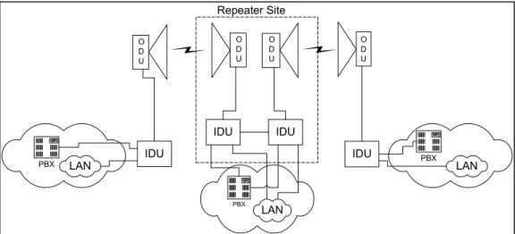
Repeater Site
At certain conditions it may become necessary to install one or more repeater sites. With the existing equipment it is possible to establish the repeater site by installing two complete CFM equipment sets (see Figure 1). This configuration allows the use of functions offered by the Service channel as well as the use of interfaces for data streams to be added or dropped in the both CFM– 34 IDUs at the repeater site.
Figure 1. Typical configuration of the repeater site IDU PBX LAN IDU IDU PBX LAN PBX LAN IDU Repeater Site O D U O D U O D U O D U
Outdoor Unit and Antenna
General
The Outdoor Unit (ODU) and the antenna forms the outdoor part of the CFM site (one side of the hop). The Outdoor Unit is a radio unit which can be either directly connected to the antenna or installed separately using flexible waveguide. The Radio Unit is connected to the IDU using a single 50 Ω coaxial cable, for more detailed information on the IDU–ODU cable please refer to section IDU–ODU Cable, page 1.
Radio Unit
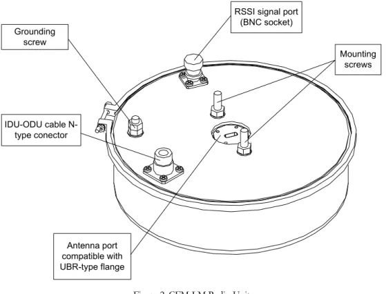
The CFM-LM Radio Unit is implemented as a weatherproof white circular housing weighting 2.5 kg.
There are following external features:
• UBR flange in the centre of the case for connection to the antenna,
• The interface for connection to the IDU (N-type socket),
• The test port for antenna alignment (BNC socket).
Figure 2. CFM-LM Radio Unit
For ODU technical parameters please refer to Chapter Technical Data, page 1.
Relation of RSSI Rx signal level and received power is specified in the configuration guide (see
References)
The ODUs have the following waveguide flanges: CFM-13-LM: UBR 140,
CFM-15-LM: UBR 140, CFM-18-LM: UBR 220, CFM-22-LM: UBR 220.
For information about frequency allocation refer to Chapter Frequency Channel Arrangement, page 1. Grounding screw IDU-ODU cable N-type conector Antenna port compatible with UBR-type flange
RSSI signal port (BNC socket)
Mounting screws
The ODU contains temperature sensor and condensing moisture sensor. These indications are accessible through all available management methods. The temperature sensor indicates the temperature within the ODU, - it is normally about 60°C higher than the outer temperature. As for the triggered moisture sensor, it is most likely that the ODU cover is opened. This is abnormal operational condition and should be averted as soon as possible.
Labelling
Each Outdoor Unit is labelled.
The ODU is uniquely identified by the combination of product number (“P/N”) and serial number.
The label contains five squares (see figures below). One of the first two squares will have a letter L or H (other is blank) which denotes what band side the specific radio operates (Low or High). Either the third square or the fourth square will have letter A or B (the fourth square – letter A or the fifth square – letter B), which denotes the subband. The fifth square is blank.
ODU Functional Design
The radio unit consists of the following components (please refer to Figure 4):
• Cable interface
• IF module
• Receiver & Transmitter units
• Controller module
• Synthesizer module
• Duplexer
Figure 4. The CFM-LM radio unit block diagram
Wav eguide to Ante nna Coax cable to IDU RX RSSI output Ca bl e In terf ace Controller Module Receiver Transmitter Synthesizer Module Intermediate Frequency Module D upl ex er
ODU
Cable Interface
There are two functions accomplished in the cable interface:
• The power supply of the radio unit,
• The provision of signal transportation to the IDU over the coaxial cable.
The supply voltage, which can be in the range from 20 to 60 V with both polarities in relation to the ground, is supplied from the IDU over the cable.
A 350 MHz frequency signal, modulated with the filtered data signal, is received from the IDU. The cable interface contains the FM demodulation unit. The data signal from the output of the FM demodulation unit is forwarded to the modulation input of the voltage-controlled oscillator in the transmitting part of the synthesizer module. Thus the data signal is transported from the IDU to the ODU. The cable can be so long until the maximum attenuation of the signal does not exceed 20 dB. The FM demodulators produce a voltage, which is proportional to the logarithm of the 350 MHz carrier power (cable RSSI). This voltage is supplied to the controller module and is used to check if the allowed length of the coaxial cable is not exceeded.
The transportation of the data signal from the ODU to the IDU is carried out as follows: limited (constant level) 140 MHz intermediate frequency signal is supplied to the coaxial cable through the amplifier and the band-pass filter in the cable interface. This signal is frequency-modulated (the modulation is performed in the transmitter of the opposite station) and the length of the cable has no effect on the transmitted data signal, unless the 20 dB attenuation limit is kept up. Since the filtration and restriction of the intermediate frequency signal is performed in the radio unit, the transportation of the signal to the IDU has no effect on the sensitivity of the receiver.
Additional data signal with a transmission rate of 9 kbps is transmitted over the same coaxial cable from the IDU to the ODU and vice versa. Both signals carry telemetry data between ODU and IDU. This is performed using two carriers with pulse-modulated amplitude. The data from the ODU to the IDU are transmitted on a 6 MHz carrier, but from the IDU to the ODU – on a 4.5 MHz carrier.
Intermediate Frequency Module
The IF module is used for the second conversion and filtering of the signal. The 1542 MHz intermediate frequency signal is passed to the IF block from the first converter in the receiver. Synthesized 1402 MHz oscillator jointly with a mixer transforms the first intermediate frequency into the second intermediate frequency of 140 MHz. The second IF signal is filtered with a surface acoustic waves (SAW) filter, after the filtering the signal arrives to the logarithmic amplifier that has a signal limiter at the output. The logarithmic amplifier has an additional function – an exact measurement of the power of the received signal. The direct voltage on the output of this amplifier is supplied to the controller module and is used for the measurements.
Synthesizer Module
The synthesizer module has two very similar frequency synthesizers. One synthesizer supplies the oscillator signal to the first mixer. The second has a modulation input and it supplies the signal to the transmitter. The synthesizers are based on the voltage-controlled oscillators (VCO). The frequency of VCOs is stabilized and modified, using a phase-locked loop (PLL).
Receiver
The receiver performs amplification of the received signal by means of a low-noise amplifier (LNA), which is a monolithic microwave integrated circuit (MMIC), enclosed in a special package. The signal after that is forwarded to the mirror-channel filter, which is installed with the purpose to reduce the noise factor of the receiver. From the point of view of the input signal, sufficient attenuation of the mirror channel is provided by the duplexer filter.
The amplified signal is passed to the subharmonic mixer, where it is converted to the frequency of 1542 MHz. This mixer is also a monolithic microwave integrated circuit.
Transmitter
In the transmitter, the output frequency of the synthesizer module is doubled and the resulting signal is amplified. Both functions are performed by one monolithic microwave integrated circuit. By switching on and off the supply voltage, it is possible to switch on and off the transmitter. TX block has a waveguide output.
Duplexer
The duplexer is intended for combining the signals from the transmitter and receiver into the single waveguide to the antenna. This device is a narrow-band waveguide filter with one common waveguide output. Tx frequency setting in one station should match Rx frequency at the other station and vice versa.
Controller Module
The controller module is intended to ensure the control and checking of the radio unit and a link with the IDU.
The control functions are intended for:
• Setting of the synthesizer frequencies
• Setting of the output power
• Switching the receiver on and off The checking functions are provided for:
• Measuring the level of the received signal
• Measuring the signal attenuation in the cable
• Checking the synchronism of the synthesizers
• Measuring the temperature of the radio unit
• Checking the humidity in the radio unit
Settings of the frequency and transmitter power are accomplished from the IDU management interface or through the management console. The ODU has its own management controller and the memory for configuration storage. The configuration information is stored in the ODU management controller EPROM. Consequently, in the case of the ODU replacement, the current configuration of link may change therefore the new parameters should be set.
SAF Tehnika is shipping CFM-LM Outdoor Units with the following default settings:
• The transmitter is switched off (TxPower=off);
• The channel is set to one in the middle of the sub-band.
The Tx channel can be adjusted from the IDU or using other available management methods. The arrangement of frequency channels is given in tables in Chapter Frequency Channel Arrangement.
Frequency Channel Arrangement
Table 1. Tx/Rx channel centre frequencies for the CFM-13-LM series Radio operating in 13 GHz band with the channel spacing of 7 MHz; duplex shift is 266 MHz; the plan corresponds to CEPT/ERC recommendation 12-02 E. N LA HA N LB HB 0 12754,5 13020,5 16 12866,5 13132,5 1 12761,5 13027,5 17 12873,5 13139,5 2 12768,5 13034,5 18 12880,5 13146,5 3 12775,5 13041,5 19 12887,5 13153,5 4 12782,5 13048,5 20 12894,5 13160,5 5 12789,5 13055,5 21 12901,5 13167,5 6 12796,5 13062,5 22 12908,5 13174,5 7 12803,5 13069,5 23 12915,5 13181,5 8 12810,5 13076,5 24 12922,5 13188,5 9 12817,5 13083,5 25 12929,5 13195,5 10 12824,5 13090,5 26 12936,5 13202,5 11 12831,5 13097,5 27 12943,5 13209,5 12 12838,5 13104,5 28 12950,5 13216,5 13 12845,5 13111,5 29 12957,5 13223,5 14 12852,5 13118,5 30 12964,5 13230,5 15 12859,5 13125,5 31 12971,5 13237,5
Table 2. Tx/Rx channel centre frequencies for the CFM-13-LM series Radio operating in 13 GHz band with the channel spacing of 14 MHz; duplex shift is 266 MHz; the plan corresponds to CEPT/ERC recommendation 12-02 E. N LA HA N LB HB 0 12758 13024 8 12870 13136 1 12772 13038 9 12884 13150 2 12786 13052 10 12898 13164 3 12800 13066 11 12912 13178 4 12814 13080 12 12926 13192 5 12828 13094 13 12940 13206 6 12842 13108 14 12954 13220 7 12856 13122 15 12968 13234
Table 3. Tx/Rx channel centre frequencies for the CFM-15-LM series Radio operating in 15 GHz band with the channel spacing of 7 MHz; duplex shift is 728 MHz; the plan corresponds to CEPT/ERC recommendation 12-07 E. N L H N L H 0 14504,5 15232,5 8 14560,5 15288,5 1 14511,5 15239,5 9 14567,5 15295,5 2 14518,5 15246,5 10 14574,5 15302,5 3 14525,5 15253,5 11 14581,5 15309,5 4 14532,5 15260,5 12 14588,5 15316,5 5 14539,5 15267,5 13 14595,5 15323,5 6 14546,5 15274,5 14 14602,5 15330,5 7 14553,5 15281,5 15 14609,5 15337,5
Table 4. Tx/Rx channel centre frequencies for the CFM-15-LM series Radio operating in 15 GHz band with the channel spacing of 14 MHz; duplex shift is 728 MHz; the plan corresponds to CEPT/ERC recommendation 12-07 E. N L H 0 14515 15243 1 14529 15257 2 14543 15271 3 14557 15285 4 14571 15299 5 14585 15313 6 14599 15327 7 14613 15341
Table 5. Tx/Rx channel centre frequencies for the CFM-15-LM series Radio operating in 15 GHz band with the channel spacing of 28 MHz; duplex shift is 728 MHz; the plan corresponds to CEPT/ERC recommendation 12-07 E. N L H 0 14515 15243 1 14543 15271 2 14571 15299 3 14599 15327
Table 6. Tx/Rx channel centre frequencies for the CFM-15-LM series Radio operating in 15 GHz band with the channel spacing of 7 MHz; duplex shift is 420 MHz; the plan corresponds to ITU-R recommendation F.636 N LA HA N LA HA N LB HB N LA HA 0 14504,5 14924,5 15 14609,5 15029,5 30 14714,5 15134,5 45 14819,5 15239,5 1 14511,5 14931,5 16 14616,5 15036,5 31 14721,5 15141,5 46 14826,5 15246,5 2 14518,5 14938,5 17 14623,5 15043,5 32 14728,5 15148,5 47 14833,5 15253,5 3 14525,5 14945,5 18 14630,5 15050,5 33 14735,5 15155,5 48 14840,5 15260,5 4 14532,5 14952,5 19 14637,5 15057,5 34 14742,5 15162,5 49 14847,5 15267,5 5 14539,5 14959,5 20 14644,5 15064,5 35 14749,5 15169,5 50 14854,5 15274,5 6 14546,5 14966,5 21 14651,5 15071,5 36 14756,5 15176,5 51 14861,5 15281,5 7 14553,5 14973,5 22 14658,5 15078,5 37 14763,5 15183,5 52 14868,5 15288,5 8 14560,5 14980,5 23 14665,5 15085,5 38 14770,5 15190,5 53 14875,5 15295,5 9 14567,5 14987,5 24 14672,5 15092,5 39 14777,5 15197,5 54 14882,5 15302,5 10 14574,5 14994,5 25 14679,5 15099,5 40 14784,5 15204,5 55 14889,5 15309,5 11 14581,5 15001,5 26 14686,5 15106,5 41 14791,5 15211,5 56 14896,5 15316,5 12 14588,5 15008,5 27 14693,5 15113,5 42 14798,5 15218,5 57 14903,5 15323,5 13 14595,5 15015,5 28 14700,5 15120,5 43 14805,5 15225,5 58 14910,5 15330,5 14 14602,5 15022,5 29 14707,5 15127,5 44 14812,5 15232,5 59 14917,5 15337,5
Table 7. Tx/Rx channel centre frequencies for the CFM-15-LM series Radio operating in 15 GHz band with the channel spacing of 14 MHz; duplex shift is 420 MHz; the plan corresponds to ITU-R recommendation F.636 N LA HA N LB HB 0 14515,0 14935,0 15 14725,0 15145,0 1 14529,0 14949,0 16 14739,0 15159,0 2 14543,0 14963,0 17 14753,0 15173,0 3 14557,0 14977,0 18 14767,0 15187,0 4 14571,0 14991,0 19 14781,0 15201,0 5 14585,0 15005,0 20 14795,0 15215,0 6 14599,0 15019,0 21 14809,0 15229,0 7 14613,0 15033,0 22 14823,0 15243,0 8 14627,0 15047,0 23 14837,0 15257,0 9 14641,0 15061,0 24 14851,0 15271,0 10 14655,0 15075,0 25 14865,0 15285,0 11 14669,0 15089,0 26 14879,0 15299,0 12 14683,0 15103,0 27 14893,0 15313,0 13 14697,0 15117,0 28 14907,0 15327,0 14 14711,0 15131,0 29 14921,0 15341,0
Table 8. Tx/Rx channel centre frequencies for the CFM-15-LM series Radio operating in 15 GHz band with the channel spacing of 28 MHz; duplex shift is 420 MHz; the plan corresponds to ITU-R recommendation F.636 N LA HA N LB HB 0 14515,0 14935,0 8 14739,0 15159,0 1 14543,0 14963,0 9 14767,0 15187,0 2 14571,0 14991,0 10 14795,0 15215,0 3 14599,0 15019,0 11 14823,0 15243,0 4 14627,0 15047,0 12 14851,0 15271,0 5 14655,0 15075,0 13 14879,0 15299,0 6 14683,0 15103,0 14 14907,0 15327,0 7 14711,0 15131,0
Table 9. Tx/Rx channel centre frequencies for the CFM-18-LM series Radio operating in 18 GHz band with the channel spacing of 13.75 MHz; duplex shift is 1010 MHz; the plan corresponds to CEPT/ERC recommendation 12-03 E. N LA HA N LB HB 0 17713,75 18723,75 35 18195,00 19205,00 1 17727,50 18737,50 36 18208,75 19218,75 2 17741,25 18751,25 37 18222,50 19232,50 3 17755,00 18765,00 38 18236,25 19246,25 4 17768,75 18778,75 39 18250,00 19260,00 5 17782,50 18792,50 40 18263,75 19273,75 6 17796,25 18806,25 41 18277,50 19287,50 7 17810,00 18820,00 42 18291,25 19301,25 8 17823,75 18833,75 43 18305,00 19315,00 9 17837,50 18847,50 44 18318,75 19328,75 10 17851,25 18861,25 45 18332,50 19342,50 11 17865,00 18875,00 46 18346,25 19356,25 12 17878,75 18888,75 47 18360,00 19370,00 13 17892,50 18902,50 48 18373,75 19383,75 14 17906,25 18916,25 49 18387,50 19397,50 15 17920,00 18930,00 50 18401,25 19411,25 16 17933,75 18943,75 51 18415,00 19425,00 17 17947,50 18957,50 52 18428,75 19438,75 18 17961,25 18971,25 53 18442,50 19452,50 19 17975,00 18985,00 54 18456,25 19466,25 20 17988,75 18998,75 55 18470,00 19480,00 21 18002,50 19012,50 56 18483,75 19493,75 22 18016,25 19026,25 57 18497,50 19507,50 23 18030,00 19040,00 58 18511,25 19521,25 24 18043,75 19053,75 59 18525,00 19535,00 25 18057,50 19067,50 60 18538,75 19548,75 26 18071,25 19081,25 61 18552,50 19562,50 27 18085,00 19095,00 62 18566,25 19576,25 28 18098,75 19108,75 63 18580,00 19590,00 29 18112,50 19122,50 64 18593,75 19603,75 30 18126,25 19136,25 65 18607,50 19617,50 31 18140,00 19150,00 66 18621,25 19631,25 32 18153,75 19163,75 67 18635,00 19645,00 33 18167,50 19177,50 68 18648,75 19658,75 34 18181,25 19191,25 69 18662,50 19672,50
Table 10. Tx/Rx channel centre frequencies for the CFM-18-LM series Radio operating in 18 GHz band with the channel spacing of 27.5 MHz; duplex shift is 1010 MHz; the plan corresponds to CEPT/ERC recommendation 12-03 E. N LA HA N LB HB 0 17727,5 18737,5 18 18222,5 19232,5 1 17755,0 18765,0 19 18250,0 19260,0 2 17782,5 18792,5 20 18277,5 19287,5 3 17810,0 18820,0 21 18305,0 19315,0 4 17837,5 18847,5 22 18332,5 19342,5 5 17865,0 18875,0 23 18360,0 19370,0 6 17892,5 18902,5 24 18387,5 19397,5 7 17920,0 18930,0 25 18415,0 19425,0 8 17947,5 18957,5 26 18442,5 19452,5 9 17975,0 18985,0 27 18470,0 19480,0 10 18002,5 19012,5 28 18497,5 19507,5 11 18030,0 19040,0 29 18525,0 19535,0 12 18057,5 19067,5 30 18552,5 19562,5 13 18085,0 19095,0 31 18580,0 19590,0 14 18112,5 19122,5 32 18607,5 19617,5 15 18140,0 19150,0 33 18635,0 19645,0
Table 11. Tx/Rx channel centre frequencies for the CFM-22-LM series Radio operating in 23 GHz band with the channel spacing of 7 MHz and duplex shift of 1008 MHz; the plan corresponds to ERC recommendation T/R 13-02 E. N L H N L H 2 22011,5 23019,5 86 22305,5 23313,5 4 22018,5 23026,5 88 22312,5 23320,5 6 22025,5 23033,5 90 22319,5 23327,5 8 22032,5 23040,5 92 22326,5 23334,5 10 22039,5 23047,5 94 22333,5 23341,5 12 22046,5 23054,5 96 22340,5 23348,5 14 22053,5 23061,5 98 22347,5 23355,5 16 22060,5 23068,5 100 22354,5 23362,5 18 22067,5 23075,5 102 22361,5 23369,5 20 22074,5 23082,5 104 22368,5 23376,5 22 22081,5 23089,5 106 22375,5 23383,5 24 22088,5 23096,5 108 22382,5 23390,5 26 22095,5 23103,5 110 22389,5 23397,5 28 22102,5 23110,5 112 22396,5 23404,5 30 22109,5 23117,5 114 22403,5 23411,5 32 22116,5 23124,5 116 22410,5 23418,5 34 22123,5 23131,5 118 22417,5 23425,5 36 22130,5 23138,5 120 22424,5 23432,5 38 22137,5 23145,5 122 22431,5 23439,5 40 22144,5 23152,5 124 22438,5 23446,5 42 22151,5 23159,5 126 22445,5 23453,5 44 22158,5 23166,5 128 22452,5 23460,5 46 22165,5 23173,5 130 22459,5 23467,5 48 22172,5 23180,5 132 22466,5 23474,5 50 22179,5 23187,5 134 22473,5 23481,5 52 22186,5 23194,5 136 22480,5 23488,5 54 22193,5 23201,5 138 22487,5 23495,5 56 22200,5 23208,5 140 22494,5 23502,5 58 22207,5 23215,5 142 22501,5 23509,5 60 22214,5 23222,5 144 22508,5 23516,5 62 22221,5 23229,5 146 22515,5 23523,5 64 22228,5 23236,5 148 22522,5 23530,5 66 22235,5 23243,5 150 22529,5 23537,5 68 22242,5 23250,5 152 22536,5 23544,5 70 22249,5 23257,5 154 22543,5 23551,5 72 22256,5 23264,5 156 22550,5 23558,5 74 22263,5 23271,5 158 22557,5 23565,5 76 22270,5 23278,5 160 22564,5 23572,5 78 22277,5 23285,5 162 22571,5 23579,5 80 22284,5 23292,5 164 22578,5 23586,5 82 22291,5 23299,5 166 22585,5 23593,5 84 22298,5 23306,5
Table 12. Tx/Rx channel centre frequencies for the CFM-22-LM series Radio operating in 23 GHz band with the channel spacing of 14 MHz and duplex shift of 1008 MHz; the plan corresponds to ERC recommendation T/R 13-02 E. N L H N L H 3 22015 23023 87 22309 23317 7 22029 23037 91 22323 23331 11 22043 23051 95 22337 23345 15 22057 23065 99 22351 23359 19 22071 23079 103 22365 23373 23 22085 23093 107 22379 23387 27 22099 23107 111 22393 23401 31 22113 23121 115 22407 23415 35 22127 23135 119 22421 23429 39 22141 23149 123 22435 23443 43 22155 23163 127 22449 23457 47 22169 23177 131 22463 23471 51 22183 23191 135 22477 23485 55 22197 23205 139 22491 23499 59 22211 23219 143 22505 23513 63 22225 23233 147 22519 23527 67 22239 23247 151 22533 23541 71 22253 23261 155 22547 23555 75 22267 23275 159 22561 23569 79 22281 23289 163 22575 23583 83 22295 23303
Table 13. Tx/Rx channel centre frequencies for the CFM-22-LM series Radio operating in 23 GHz band with the channel spacing of 28 MHz and duplex shift of 1008 MHz; the plan corresponds to ERC recommendation T/R 13-02 E. N L H N L H 5 22022 23030 85 22302 23310 13 22050 23058 93 22330 23338 21 22078 23086 101 22358 23366 29 22106 23114 109 22386 23394 37 22134 23142 117 22414 23422 45 22162 23170 125 22442 23450 53 22190 23198 133 22470 23478 61 22218 23226 141 22498 23506 69 22246 23254 149 22526 23534 77 22274 23282 157 22554 23562
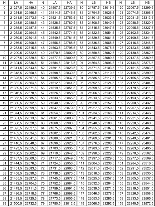
Table 14. Tx/Rx channel centre frequencies for the CFM-22-LM series Radio operating in 23 GHz band with the channel spacing of 7 MHz and duplex shift of 1232 MHz; the plan corresponds to ITU-R Rec. F.637-3. N LA HA N LA HA N LB HB N LB HB 0 21227,5 22459,5 40 21507,5 22739,5 80 21787,5 23019,5 120 22067,5 23299,5 1 21234,5 22466,5 41 21514,5 22746,5 81 21794,5 23026,5 121 22074,5 23306,5 2 21241,5 22473,5 42 21521,5 22753,5 82 21801,5 23033,5 122 22081,5 23313,5 3 21248,5 22480,5 43 21528,5 22760,5 83 21808,5 23040,5 123 22088,5 23320,5 4 21255,5 22487,5 44 21535,5 22767,5 84 21815,5 23047,5 124 22095,5 23327,5 5 21262,5 22494,5 45 21542,5 22774,5 85 21822,5 23054,5 125 22102,5 23334,5 6 21269,5 22501,5 46 21549,5 22781,5 86 21829,5 23061,5 126 22109,5 23341,5 7 21276,5 22508,5 47 21556,5 22788,5 87 21836,5 23068,5 127 22116,5 23348,5 8 21283,5 22515,5 48 21563,5 22795,5 88 21843,5 23075,5 128 22123,5 23355,5 9 21290,5 22522,5 49 21570,5 22802,5 89 21850,5 23082,5 129 22130,5 23362,5 10 21297,5 22529,5 50 21577,5 22809,5 90 21857,5 23089,5 130 22137,5 23369,5 11 21304,5 22536,5 51 21584,5 22816,5 91 21864,5 23096,5 131 22144,5 23376,5 12 21311,5 22543,5 52 21591,5 22823,5 92 21871,5 23103,5 132 22151,5 23383,5 13 21318,5 22550,5 53 21598,5 22830,5 93 21878,5 23110,5 133 22158,5 23390,5 14 21325,5 22557,5 54 21605,5 22837,5 94 21885,5 23117,5 134 22165,5 23397,5 15 21332,5 22564,5 55 21612,5 22844,5 95 21892,5 23124,5 135 22172,5 23404,5 16 21339,5 22571,5 56 21619,5 22851,5 96 21899,5 23131,5 136 22179,5 23411,5 17 21346,5 22578,5 57 21626,5 22858,5 97 21906,5 23138,5 137 22186,5 23418,5 18 21353,5 22585,5 58 21633,5 22865,5 98 21913,5 23145,5 138 22193,5 23425,5 19 21360,5 22592,5 59 21640,5 22872,5 99 21920,5 23152,5 139 22200,5 23432,5 20 21367,5 22599,5 60 21647,5 22879,5 100 21927,5 23159,5 140 22207,5 23439,5 21 21374,5 22606,5 61 21654,5 22886,5 101 21934,5 23166,5 141 22214,5 23446,5 22 21381,5 22613,5 62 21661,5 22893,5 102 21941,5 23173,5 142 22221,5 23453,5 23 21388,5 22620,5 63 21668,5 22900,5 103 21948,5 23180,5 143 22228,5 23460,5 24 21395,5 22627,5 64 21675,5 22907,5 104 21955,5 23187,5 144 22235,5 23467,5 25 21402,5 22634,5 65 21682,5 22914,5 105 21962,5 23194,5 145 22242,5 23474,5 26 21409,5 22641,5 66 21689,5 22921,5 106 21969,5 23201,5 146 22249,5 23481,5 27 21416,5 22648,5 67 21696,5 22928,5 107 21976,5 23208,5 147 22256,5 23488,5 28 21423,5 22655,5 68 21703,5 22935,5 108 21983,5 23215,5 148 22263,5 23495,5 29 21430,5 22662,5 69 21710,5 22942,5 109 21990,5 23222,5 149 22270,5 23502,5 30 21437,5 22669,5 70 21717,5 22949,5 110 21997,5 23229,5 150 22277,5 23509,5 31 21444,5 22676,5 71 21724,5 22956,5 111 22004,5 23236,5 151 22284,5 23516,5 32 21451,5 22683,5 72 21731,5 22963,5 112 22011,5 23243,5 152 22291,5 23523,5 33 21458,5 22690,5 73 21738,5 22970,5 113 22018,5 23250,5 153 22298,5 23530,5 34 21465,5 22697,5 74 21745,5 22977,5 114 22025,5 23257,5 154 22305,5 23537,5 35 21472,5 22704,5 75 21752,5 22984,5 115 22032,5 23264,5 155 22312,5 23544,5 36 21479,5 22711,5 76 21759,5 22991,5 116 22039,5 23271,5 156 22319,5 23551,5 37 21486,5 22718,5 77 21766,5 22998,5 117 22046,5 23278,5 157 22326,5 23558,5 38 21493,5 22725,5 78 21773,5 23005,5 118 22053,5 23285,5 158 22333,5 23565,5 39 21500,5 22732,5 79 21780,5 23012,5 119 22060,5 23292,5 159 22340,5 23572,5
Table 15. Tx/Rx channel centre frequencies for the CFM-22-LM series Radio operating in 23 GHz band with the channel spacing of 14 MHz and duplex shift of 1232 MHz; the plan corresponds to ITU-R Rec. F.637-3. N LA HA N LA HA N LB HB N LB HB 0 21231 22463 20 21511 22743 40 21791 23023 60 22071 23303 1 21245 22477 21 21525 22757 41 21805 23037 61 22085 23317 2 21259 22491 22 21539 22771 42 21819 23051 62 22099 23331 3 21273 22505 23 21553 22785 43 21833 23065 63 22113 23345 4 21287 22519 24 21567 22799 44 21847 23079 64 22127 23359 5 21301 22533 25 21581 22813 45 21861 23093 65 22141 23373 6 21315 22547 26 21595 22827 46 21875 23107 66 22155 23387 7 21329 22561 27 21609 22841 47 21889 23121 67 22169 23401 8 21343 22575 28 21623 22855 48 21903 23135 68 22183 23415 9 21357 22589 29 21637 22869 49 21917 23149 69 22197 23429 10 21371 22603 30 21651 22883 50 21931 23163 70 22211 23443 11 21385 22617 31 21665 22897 51 21945 23177 71 22225 23457 12 21399 22631 32 21679 22911 52 21959 23191 72 22239 23471 13 21413 22645 33 21693 22925 53 21973 23205 73 22253 23485 14 21427 22659 34 21707 22939 54 21987 23219 74 22267 23499 15 21441 22673 35 21721 22953 55 22001 23233 75 22281 23513 16 21455 22687 36 21735 22967 56 22015 23247 76 22295 23527 17 21469 22701 37 21749 22981 57 22029 23261 77 22309 23541 18 21483 22715 38 21763 22995 58 22043 23275 78 22323 23555 19 21497 22729 39 21777 23009 59 22057 23289 79 22337 23569
Table 16. Tx/Rx channel centre frequencies for the CFM-22-LM series Radio operating in 23 GHz band with the channel spacing of 28 MHz and duplex shift of 1232 MHz; the plan corresponds to ITU-R Rec. F.637-3. N LA HA N LB HB 0 21238 22470 20 21798 23030 1 21266 22498 21 21826 23058 2 21294 22526 22 21854 23086 3 21322 22554 23 21882 23114 4 21350 22582 24 21910 23142 5 21378 22610 25 21938 23170 6 21406 22638 26 21966 23198 7 21434 22666 27 21994 23226 8 21462 22694 28 22022 23254 9 21490 22722 29 22050 23282 10 21518 22750 30 22078 23310 11 21546 22778 31 22106 23338 12 21574 22806 32 22134 23366 13 21602 22834 33 22162 23394 14 21630 22862 34 22190 23422 15 21658 22890 35 22218 23450 16 21686 22918 36 22246 23478 17 21714 22946 37 22274 23506 18 21742 22974 38 22302 23534 19 21770 23002 39 22330 23562
Antenna Unit
SAF Tehnika offers the following types of antennas for the CFM site installation according to availability and distance requirements:
• CFM-22ANT 25 cm Lens–Horn antenna (manufactured by SAF Tehnika)
Figure 5. CFM-22ANT 25 cm Lens–Horn antenna
• CLGA6002 60 cm parabolic antenna (manufactured by COMHAT)
• CLGA1202 120 cm parabolic antenna (manufactured by COMHAT)
Figure 6. CLGA61202 120 cm parabolic antenna
Along with parabolic antennas SAF Tehnika offers special adaptation kit for connection of the radio unit to the antenna. For more detailed information on the adaptation kit please refer to paragraph Outdoor Accessories, page 1.
As an alternative to antennas offered by SAF Tehnika, other antennas can be used.
SAF Tehnika offers mounting kits for other antennas, the customer should only specify what type of antenna he has.
As an additional accessory SAF Tehnika offers the universal mounting bracket in order to fit the antenna to tubes with a diameter of 70 – 90 mm. The special adaptation kit may be used to connect the radio unit to other types of antennas.
The azimuth of all types of antennas can be changed through 0 – 3600 and the elevation can be
adjusted by ±150.
For rough and fine antenna alignment adjustments, a multimeter and the cable for digital multimeter are required.
All screws complemented with Lens–Horn antenna for connection and adjustment are in stainless steel and all nuts are in brass (stainless).
Indoor Unit
General
The Indoor Unit (IDU) is the mandatory component of the CFM-LM microwave radio system and it provides:
− Means of interconnecting the Outdoor Unit and the user equipment,
− Local and remote management functionality,
− Supply voltage to the ODU.
The following CFM-LM Indoor units are available:
• CFM-8-REB • CFM-34-REBM • CFM-8-MUX • CFM-16-MUX • CFM-8-4E1 • CFM-16-8E1 • CFM-34-16E1
The IDU is intended for installation in weather protected equipment shelters or inside buildings. Each of the IDU terminals is implemented as 19” rack mountable aluminium 1U high unit. The depth of the unit is 230 mm without front panel handles (270 mm with handles).
All traffic interfaces are located on the front of the IDU.
The CFM series LM IDUs provide the following management ports:
− RS232 serial management port, DB9 connector is located at the rear panel of the IDU,
− 10Base–T Ethernet management port, RJ–45 socket is located at the rear side of the IDU panel,
− Alarm port (optional), e.i., alarm relay outputs for power supply failure, Synch Lost alarm, Radio alarm, and transmitter PLL failure, as well as four additional inputs for user equipment.
A maximum of 350 mm deep rack is required for the IDU to be mounted, from mounting points of front panel including space behind the unit for cables to RF, Grounding point, Ethernet and Serial management interfaces.
Some space is required in front of the IDU for traffic interface cables, - as a minimum 5 cm from the front panel are needed for Ethernet patch-cable and E1 interface cable.
As a minimum of 10 cm to 12 cm of supplementary space is required (mainly depending on the RF cable type) behind the IDU for management interface cables and RF cable. :
CFM-8-REB IDU
The Remote Ethernet Bridge IDU is fixed configuration Ethernet bridge, provides full radio capacity of 8 Mbps to 10Base–T UTP Ethernet interface on the LAN side.
CFM-8-REB S L R A CLEAR ENTER -48V+
WTX WRXLINK LTX LRX COL ERR R LAN
Figure 7. The CFM-8-REB IDU front panel
Figure 8. The rear panel of the CFM-8-REB IDU
5 cm Ethernet, E1 4 cm 23 cm (9.10 ") (3.15 ") (1.57 ") (16.93 ") 42.6 cm (19.29 ") 48.6 cm 12 cm (4.72 ")
CFM-34-REBM IDU
The Modular Fast Ethernet bridge IDU has the modular configuration and provides 100Base-Tx UTP LAN interface plus two interface slots that can be equipped with two interface modules (V.35, E1 or 10Base-T Ethernet) providing additional traffic interfaces with a maximum capacity of 2 Mbps each.
Figure 9. The CFM-34-REBM IDU front panel
CFM-8-MUX and CFM-16-MUX IDU
The CFM-8-MUX and the CFM-16-MUX Indoor Units are modular and can be equipped with 4 interface modules (V.35, E1 or 10Base-T Ethernet) providing maximum WAN data rate of 8 Mbps (CFM-8-MUX) or 16 Mbps (CFM-16-MUX). - 48V + CFM-8-MUX SL RA CLEAR ENTER OUT E1 IN TX AIS LB RX C D S R V.35 REB TX RX TX RX LAN WAN
Figure 10. The CFM-8-MUX IDU front panel
CFM E1 Indoor Units
All CFM series E1 IDUs are fixed configuration multiplexers providing multiplexing of E1 channels into a single 34 Mbps stream.
The CFM-8-4E1 IDU provide 4 E1 channel ports on BNC and RJ-45 connectors. The CFM-16-8E1 IDU provide 8 E1 channel ports on SMB or RJ-45 connectors. The CFM-34-16E1 IDU provide 4 E1 channel ports on RJ-45 connectors.
CFM-16-8E1 S L R A CLEAR ENTER -48V+ 1 2 3 4 5 6 7 8
Figure 11. CFM-16-8E1 IDU front panel
LAN 100M CLEAR ENTER SL RA CFM-8-REBM Slot 3 Slot 4
IDU Functional Design
The CFM IDUs consist of the following functional blocks (see Figure 12 and Figure 13):
• Cable interface
• Base-band modem
• Power supply unit
• Management controller
• Multiplexer (MUX) board (refers to the multiplexer, E1 and modular Fast Ethernet bridge IDUs only);
• Ethernet Interface board (refers to the CFM-8-REB only)
• Traffic interfaces
Figure 12. The CFM series E1 IDU block diagram
Figure 13. The CFM-8-REB IDU block diagram
Cable Interface Management Controller Base-band Modem Power Supply Unit MUX C oax c ab le to OD U
IDU
Ethernet RS232 LCD E 1 Int er fa ce E1 I nte rf ace . . . . (4 … 16) x E1 Interfaces . . . . Alarm Port Cable Interface Management Controller Base-band Modem Power Supply Unit Ethernet Interface Board Co ax c a ble to ODUIDU
Ethernet RS232 LCDCable Interface
The cable interface provides the power supply voltages for all blocks and the ODU. Since the DC-DC of the power supply is isolated, the supply voltages of the device may be positive or negative in respect to the ground.
Like the ODU, the extra telemetry data flow is transmitted using the method of the pulse-amplitude modulation.
The received 140 MHz signal (from ODU) is demodulated in the frequency demodulator, from which the signal is fed to the MUX module.
From the MUX module the four level data signal is passed to the 350 MHz voltage controlled generator. The carrier-modified signal is passed through the buffer amplifier and the band pass filter to the cable, which is connected to the ODU.
Base-band Modem
Base-band modem performs coding, decoding and scrambling of the four level data signal.
Management Controller
The management controller provides the control of and checking of the IDU and ODU, as well as the management and monitoring functionality. Management controller contains TCP/IP stack and acts as an IP packet router for management traffic. There is Web page, SNMP agent and Telnet client/servers implemented providing comprehensive management functionality and allows to integrate the CFM equipment in any telecommunications network easily.
Multiplexer (MUX)
The multiplexer module performs multiplexing and demultiplexing of the WAN data channel into interface traffic channels and 16 kbps telemetry channel.
Traffic Interfaces
The traffic interface provide physical interface between user equipment and the multiplexer. For modular IDUs (MUX and REBM type IDUs) special traffic interface modules are available:
− the E1 interface module: single E1 port module which terminates G.703 2 Mbps channel;
the E1 interface module provides two types of traffic port connectors: 120 Ω balanced interface on RJ-45 type connector and 75 Ω unbalanced interface on BNC type connectors (a pair of coaxial cables with the BNC type connectors are required);
− the V.35 interface module is provided with M.34 standard connector. The V.35 module
terminates 2, 4, 6 or 8 Mbps from multiplexer and provides user configurable data rates of 64 kbps, 128 kbps, 256 kbps, 512 kbps, 1024 kbps, 2048 kbps, 4 Mbps, 6 Mbps or 8 Mbps to single V.35 interface;
− the Remote Ethernet Bridge module (REB module). The REB module terminates 2 Mbps,
4 Mbps, 6 Mbps or 8 Mbps from multiplexer and provides single 10 Mbps 10Base-T Ethernet port on the LAN side. The REB interface module contains a complete filtering Ethernet bridge.
Ethernet Interface Board
The Ethernet interface board has a built in two-port packet switching engine. One of the ports is 10 Mbps on 10BaseT Ethernet interface (implemented as RJ-45 type connector). The other port is synchronous serial interface that is terminated in the baseband modem, hence the full capacity is terminated in the Ethernet interface board from the Radio Unit.
Update of Management Controller Software
The update of management controller software can be accomplished in two ways:
• Replacing the onboard Flash EPROM, or
• Upgrading Flash EPROM via RS232 serial port.
Upgrades to management software for management controller board are available as uploadable files from SAF Tehnika, sales partners or Web site.
Upload functionality is provided through management controller software monitor and is available via RS-232 serial port.
Upload could be performed from PC/Laptop connected to serial port of IDU from any PC terminal program with text file loading functionality.
The instructions on performing the software upload are provided with the upgrade files. There is a special management software upgrade guide available from SAF Tehnika, see References.
Cables
In order to install the CFM site, the following types of cables are needed:
• IDU–ODU cable;
• Cable to digital multimeter for antenna alignment during the installation;
• Interface cables (E1, Ethernet, V.35);
• Power cable to the IDU.
In case of necessity, SAF Tehnika can offer the aforementioned types of cables.
IDU–ODU Cable
IDU–ODU cable is a 50 Ω coaxial cable intended to interconnect the Indoor Unit with the Outdoor Unit. Any type of 50 Ω cable of good quality can be used, the cable should be equipped with N–type male connectors on each end. There are two N–type male connectors included in each radio unit delivery that fit RG–213 cables or other cables with a surface diameter of 10 mm. As the attenuation of the cable is essential particularly at 350 MHz frequency, its usage is restricted, - the attenuation of the signal should not exceed 20 dB at 350 MHz. Commonly employing RG– 213 type coaxial cable, its length may reach 100 m, LMR–400 type cable may usually reach up to 300 m in length.
Cable for Antenna Alignment
SAF Tehnika as an extra accessory offers the cable intended to connect the digital multimeter to the ODU in order to adjust the optimal antenna alignment.
This type of cable has the BNC type connector on the one end and a pair of cleats on the other end (see Figure 14). BNC connector should be connected to the BNC socket located on the front of the ODU and cleats should be attached to the multimeter.
Traffic Interface Cables
The following types of traffic interface cables could be used with CFM-LM IDU traffic interfaces:
• Cat3 unshielded twisted pair (UTP) or better for 10Base-T Ethernet; Cat5 UTP or better for 100Base-Tx Ethernet connection;
• Cat3 UTP or better for the E1 balanced interfaces;
• Any 75 Ω coaxial cable with BNC connectors for the E1 unbalanced traffic port.
For cable connector pinouts please refer to the CFM product configuration guides, see References for more information.
Management Interface Cables
• Standard Ethernet patch cables should be used with management Ethernet port of the IDU;
• Any “straight through” or modem serial cable could be used with RS-232 management port of the IDU.
Power Cable
Due to low power consumption of the CFM terminals, there are no special requirements for the cable used to connect the IDU to the DC power source. Any 2 wire power cable of good quality which fits well in SAF Tehnika’s supplied 2 pole “screw on” power connector could be used. The power connector is of 2 pole D-sub type.
Management System
General, Main Goals
The Management System offered by the CFM-LM microwave radio system provides feature rich functionality enabling easy integration of equipment into the modern telecommunication networks as well as ways to control and maintain the equipment within the network.
It conforms and is designed according to general principles of the digital network management. The CFM equipment provides both local and remote management tools.
Each CFM LM Indoor Unit houses intelligent management controller providing several services:
• TCP/IP stack
• RIP II routing
• SNMP server
• Web server
• Telnet client and server
• Command Line Interpreter
TCP/IP packets are used as a main transport mechanism for the management information, each management controller acts as a TCP/IP router for management information, this way enabling a creation of routed TCP/IP network from the CFM and other equipment.
All CFM-LM product family Indoor Units comprise several physical management interfaces:
• LCD display and keypad
• Ethernet port
• RS232 serial port
• “Over the air” Service Channel multiplexed into data stream to and from radio for far side terminal access. This feature is not available for the CFM-8-REB IDU only.
Several management methods are supported for easy and convenient managing of the equipment:
• Local management using LCD display and keypad;
• Local management using ASCII terminal attached to RS-232 management port of the IDU;
• Remote management using terminal connected through analog line and modem to the RS-232 serial management port of the IDU;
• Local or remote management over Ethernet management port of the IDU. Consequently, the equipment can be managed:
- using LCD display and keypad,
- using Command Line Interface on Terminal and/or Telnet session (via RS232 and Ethernet console ports respectively),
- using IDU Web page.
Current implementation of SNMP service is intended for data acquisition (collecting statistics) and management of the alarms.
SAF Tehnika provides private MIB and supports MIB-II RFC1213 standard MIB, this way enabling easy integration of the CFM equipment into any SNMP managed network (under any standards based SNMP management application or MIB browser), for example, HP Open View. The CFM-LM offered management platform does not highlight special PC requirements. The customer should choose the appropriate software depending on the management method(s) he prefers. The following software categories could be used:
• Terminals (e.g., Hyper Terminal);
• Telnet browsers or SNMP management applications (e.g., HP Open View);
• Web browsers (MS Internet Explorer, Netscape Navigator or other).
Physical and Logical Management Interfaces
LCD Keypad Ethernet RS-232 Serial Port MUX IF ODU MM Controller Workstation Physical management interfaces
Software components in management controller board
Radio terminal (ODU + IDU) hardware components accessible from
management system
MM
C
ontroller Boar
d
UDP TCP SNMP HTTP Telnet C omm an d Lin e I nterp reter E n gi ne Management system users IP / I CMP IF Traf fic In terf ac e(s) or Ethernet boardManagement Features
RS-232 Serial Port
RS-232 serial management port of the IDU provides Terminal management via connected PC or other terminal device or modem. The terminal connected to the serial management port provides the same management functionality as Telnet console (refer to paragraph Telnet/ASCII Console Command Interface).
In order to interconnect the IDU and the Management Terminal directly through serial ports, a
straight through modem cable is needed. The serial port of the Management Terminal should be configured as 19200 8-1-N, no data flow control.
Modem PC/Terminal Modem IDU PC/Terminal IDU RS-232 RS-232
If using modems, the management terminal is connected with the IDU remotely through a telephone line. In this case the modem, which is connected with the IDU should be set to auto answer mode.
Ethernet port
Ethernet port of the CFM-LM IDU is intended as main source of management connectivity and will provide the broadest range of management functionality:
• Web management via integrated Web server in the management software;
• SNMP management via integrated SNMP agent;
• Telnet server and CLI interface; Ethernet interface could be used to connect IDU:
− To PC/Laptop to manage IDU,
− To LAN to constantly monitor IDU,
− To router or any other TCP/IP packet network termination unit to have IDU as part of network for management information.
Telnet/ASCII Console Command Interface
Telnet/Command Line Interface functionality and command system are described in the CFM-LM Indoor Unit Configuration Guides, please refer to References, page 1.
Web Interface
The implementation of Web interface for the CFM-LM IDU provides configuration and monitoring capabilities similar to ones available using on LCD/Keypad and front panel LEDs. Currently the Web interface functionality is available through the Ethernet management port and/or service channel only.
Figure 15. Web management interface: the CFM-16-8E1 IDU channels configuration window Web interface is accessible by any standards based Web browser.
SNMP Interface
SNMP management functionality is available from any SNMP browser, by means of compiling SAF MIB to browser’s MIB base.
SAF MIB is available from:
• SAF Tehnika Web site, www.saftehnika.com
• From SAF Tehnika tech support, email: [email protected]
• Contacting SAF Tehnika or distributors.
***** SNMP QUERY STARTED *****
sysDescr.0 (octets) SAF SNMP and WWW management
sysObjectID.0 (oid) saf
sysUpTime.0 (timeticks) 0 days 00h:33m:34s.90th (201490)
productDescr.0 (octets) SAF CFM-34-REBM
description.0 (octets) SAF 23GHz microwave radio
radioAlarm.0 (int32) on(1)
signalAlarm.0 (int32) none(0)
v_01.0 (octets) Tx=23362.5MHz v_02.0 (octets) Rx=22354.5MHz v_03.0 (octets) TxPower=+20dBm v_05.0 (octets) RxLev=-109dBm v_06.0 (octets) Cable=- 26dB v_07.0 (octets) TxOut=Ok v_08.0 (octets) TxPLL=Ok v_09.0 (octets) RxPLL=Ok v_10.0 (octets) t= 23C v_11.0 (octets) Humidity=Low v_12.0 (octets) Restart= 4 v_13.0 (octets) IDU t= 27C
v_14.0 (octets) RF Cable - OFF
***** SNMP QUERY FINISHED *****
Sample of SNMP query of the CFM LM IDU
Alarm Port
The alarm port is an optional feature. The alarm port comprises:
− The set of outputs of relay switches for the CFM site supervision, the outputs are:
• Power Alarm, - warns about any problems with DC power supply of the CFM site;
• Synch Lost (SL) alarm, - this alarm triggers if multiplexer frame synchronization is lost;
• Radio Alarm (RA), - warns about the problem with ODU and/or IDU-ODU cable and/or received signal level is too low;
• TxPLL Alarm, - Tx Phase-locked Loop failure;
− The set of user inputs, these inputs are used to connect an external device that requires to be supervised.
The alarm port inputs and outputs can be supervised via SNMP manager and/or Web console. The alarm port has a DB25 type connector and is located on the rear panel of the IDU.
For more detailed information about alarm port, please refer to the Configuration Guide, the available configuration guides for the CFM equipment are listed in Chapter References.
Loop Tests
Loop tests (loopbacks) are to be used for installation, fault tracing, performance or connectivity measurements and other.
Loopback tests are accessible using local and remote management methods (except for the Web terminal).
The following loopbacks are available:
• Baseband loopback
• Interface loopbacks
• RF (Radio) loopback (see notes below)
The RF and Base-band loopbacks can be set on a fixed time interval only.
Baseband loopback
Baseband loopback: The modulated signal on the baseband modem output is immediately looped back to the receiving device. There are two baseband loop tests available:
• Analog: The analog loopback is not dual;
• Digital: The digital loopback is dual. Both Baseband loops can not be set simultaneously.
Radio loopback
RF loopback: the signal is transmitted (through the radio) and immediately received (with the same frequency) and looped back to the receiving device. This is the special operation mode, where the Rx frequency during the loopback test time is set equal to the Tx frequency. The RF loopback is not dual.
Interface loopbacks
The interface loop is set in the traffic interface module, - for MUX and REBM IDUs in the E1 and V.35 interfaces, for E1 IDUs – in the E1 transceiver chip.
The interface loopbacks are available for V.35 and E1 interfaces only, the loop test can not be set in the Ethernet interface.
Figure 16. The interface loopbacks for the CFM-16-8E1 and the CFM-34-16E1 IDUs CPU E1 G.703 HDB3 OUT IN Mul tiplexer Remote loop Local loop Analog Interface I C2 bus
Figure 17. The E1 interface module digital loopback (for the modular IDUs equipped with the E1 interface module); the analog and remote interface loopbacks are similar to those for the CFM-16-8E1 and CFM-34-16E1 IDUs
CPU OUT IN I C2 Remote loop Local loop V.35 Interface RxD DSR RxC SCTE TxD DTR RTS bus Multiplexer
Figure 18. The V.35 interface module loopback (for the modular IDUs equipped with the E1 interface module) Analog Interface Analog Interface Analog Interface
Local digital loopback
Analog loopback
Remote digital loopback
E1 G.703 E1 G.703 E1 G.703
Accessories
Outdoor Accessories
SAF Tehnika offers the following outdoor accessories:
• Adaptation kit using CFM-LM radio with COMHAT antennas (CLGA6002, CLGA1202) or all other antennas not offered by SAF Tehnika;
• Support bracket for alignment unit for 25 cm Lens–Horn antenna alignment;
• ODU mounting bracket to enable separate mounting of the CFM-LM ODU (see Figure 22).
Adaptation Kit
In order to install other antennas that are not offered by SAF Tehnika (please discuss this issue with your sales representative or with SAF Tehnika), special adaptation kit for connection of the radio unit to the antenna is offered.
The kit includes:
• ODU mounting bracket (see Figure 19.)
• Flexible waveguide
• Mounting screws and seal (O ring)
Figure 19. Radio and antenna installation using the adaptation kit
The waveguide has different flanges on the both ends, - flat flange and flange with the groove. The
Support Bracket for Alignment Unit
Alignment unit support kit is intended as the support for 25 cm Lens-Horn antenna Alignment Unit. The Support Bracket is fitted under the antenna Alignment Unit allowing to adjust azimuth by 360° (see Figure 20 and Figure 21).
Figure 20. Support bracket for Alignment
ODU Mounting Bracket
The ODU Mounting Bracket is used to install the radio unit separately from the antenna (see Figure 22).
Figure 22. The separate installation of radio and antenna using the ODU mounting bracket
The ODU mounting bracket is assembled from Alignment Unit and L-shaped bracket. The Alignment Unit is fitted to the tube, the L-shaped bracket is screwed to the ODU and then the ODU can be screwed to the Alignment Unit. The L-shaped bracket allows the ODU to be easily mounted for both horizontal and vertical polarizations.
For separate installation the flexible waveguide necessary to interconnect the ODU with the antenna is not included in the mounting kit.
Installation Tools
There are no special tools required for installation operations hence SAF Tehnika does not supply anything intended for it, however typically the installation process requires common tools listed below:
• The ODU installation requires 10 mm nut wrench;
• The SAF CFM-22ANT 25 cm Lens-Horn antenna installation requires 8 and 10 mm nut wrenches;
• CLGA6002 and CLGA1202 antenna installation requires 10, 12, 17 mm nut wrenches;
• The adaptation kit installation requires 8 mm nut wrench and 3 mm PHILLIPS screwdriver for fitting the flexible waveguide;
• The mounting of the support bracket requires 8 mm nut wrench;
Earthing Accessories
SAF Tehnika does not supply any extra special earthing accessories due to the large variety of earthing circuits one could find at the installation sites.
!
Since the IDU case is not grounded through the power connector, it is the mandatory requirement to ground the IDU using grounding screw located on the back panel of the IDU.Please note that proper grounding of all the components is essential to achieve reliable operation and lightning protection. It is important to earth both the ODU and the IDU using the same earthing circuit.
It is recommended to earth the radio cable in its lower part and for longer cable every 50 meters. Both IDU and ODU units have a reasonable lightning and overvoltage protection built in. However it is essential to fit the lightning rod on the mast head, the equipment should be fitted on the mast so that it is located in the space contained by the 45 deg. cone, formed from the top of the lightning rod to the ground. It is unacceptable to fit the antenna on the very top of the mast.
Performance and Availability Calculations
The special software (MS Excel workbook) is available through SAF Tehnika representatives or from SAF Tehnika directly to aid in the network planning considerations; it allows the user to determine the major parameters of Tx/Rx equipment according to the required availability, performance, and distance and path data.
Balancing Unit
The Balancing Unit (BU) is a passive device intended to get over from one physical interface to other, - between RJ-45 and BNC interfaces; it can be used along with the E1 IDUs with one type of traffic interface (for example, CFM-8-4E1 IDU), e.g. RJ-45 or BNC (but not both).
The BU changes up to 16 E1 traffic ports from RJ-45 (symmetrical) electrical interface to BNC (asymmetrical) and vice versa, - converts the impedance from 75 Ω to 120 Ω and vice versa. The ports are independent.
The BU is 2U high rack mountable unit (depth: 0.34 m, weight: 0.83 kg).
CFM-BU16 IN OUT 16 15 14 13 12 11 10 9 8 7 6 5 4 3 2 1
Technical Data
General Parameters
Frequency subbands and
duplex shift Refer to Chapter ODU Characteristics, page 1
Traffic interface/Bit-rate The CFM-LM Radio supported WAN speeds: 34 Mbps, 16 Mbps, 8 Mbps;
IDU model Bit-rate Traffic interface
CFM-8-4E1 4x2 Mbps G.703 E1 (RJ-45 and BNC connectors)
CFM-16-8E1 8x2 Mbps G.703 E1 (RJ-45 or SMB connectors)
CFM-34-16E1 16x2 Mbps G.703 E1 (RJ-45 connectors) CFM-34-REBM 34 Mbps 10/100Base-Tx + 2x(E1 or
10Base-T or V.35)
CFM-8-MUX 8 Mbps 3x(E1 or 10Base-T or V.35) CFM-16-MUX 16 Mbps 3x(E1 or 10Base-T or V.35) CFM-8-REB 8 Mbps 10Base-T UTP
Channel spacing (carrier
spacing) Radio data rate 34 Mbps → 28 MHz (27.50 for CFM-18-LM ODU) Radio data rate 16 Mbps → 14 MHz (13.75 for CFM-18-LM ODU) Radio data rate 8 Mbps → 7 MHz
Modulation 4 FSK
Transmitter power Refer to Chapter ODU Characteristics, page 1 Tx power attenuation 0 … 20 dB
Frequency stability +/- 10 PPM Max. input power at
antenna port +15 dBm
Receiver thresholds at antenna port (guaranteed) Bit-rate: 8 Mbps BER 10-6 BER 10-3 CFM-13-LM ODU -81 dBm -84 dBm CFM-15-LM ODU -81 dBm -84 dBm CFM-22-LM ODU -80.5 dBm -84 dBm Bit-rate: 16 Mbps BER 10-6 BER 10-3 CFM-13-LM ODU -78 dBm -81 dBm CFM-15-LM ODU -78 dBm -81 dBm CFM-18-LM ODU -77 dBm -80 dBm CFM-22-LM ODU -78.5 dBm -82 dBm Bit-rate: 34 Mbps BER 10-6 BER 10-3 CFM-15-LM ODU -75 dBm -78 dBm CFM-18-LM ODU -74 dBm -77 dBm CFM-22-LM ODU -75.5 dBm -79 dBm Background BER (ETS
EN 300 198 method) <10
-11
Waveguide flange CFM-22-LM: UBR 220 CFM-15-LM: UBR 140 CFM-13-LM: UBR 140 Cable (IDU - ODU):
single coaxial Up to 100 m of RG-213 or similar, w/ N-type connectors Ambient Temperature ODU: -33 oC to +55 oC
IDU: -5 oC to +40 oC
Power supply 20 … 60 VDC, 24 W (IDU+ODU) Mechanical data See Chapter Mechanical Data
Antenna Model: CFM-22ANT (manufactured by SAF) Type: Lens-Horn 34 dBi,
Mechanical data: 250 mm in diameter, 4.0 kg incl. alignment unit. Note: any other suitable antenna can be used.
Mechanical Data
Antenna
Antenna Weight [kg] Diameter [cm] CFM-22ANT 25 cm Lens-Horn (SAF) 4 25
CLGA6002 60 cm (COMHAT) 4.1 60
CLGA1202 120 cm (COMHAT) 25 120
Figure 24. Dimensions of the SAF 25 cm Lens-Horn antenna
250 305
37
IDU mechanical parameters
IDU model Dimensions HxWxD [mm] Weight [kg]
CFM-8-4E1 44x482x284 2.0 CFM-16-8E1 44x482x284 1.9 CFM-34-16E1 44x482x284 1.8 CFM-34-REBM 44x482x284 2.1 CFM-8-MUX 44x482x284 1.7 CFM-16-MUX 44x482x284 1.8 CFM-8-REB 44x482x284 1.7
Figure 25. Dimensions of the IDU 482
284