https://doi.org/10.3390/fib8100064
Damping properties of flax/carbon hybrid
epoxy/fibre-reinforced composites for
automotive semi-structural applications.
FAIRLIE, G. and NJUGUNA, J.
2020
This document was downloaded from
https://openair.rgu.ac.uk
© 2020 by the authors. Licensee MDPI, Basel, Switzerland.Fibers2020, 8, 64; doi:10.3390/fib8100064 www.mdpi.com/journal/fibers
Article
Damping Properties of Flax/Carbon Hybrid
Epoxy/Fibre-Reinforced Composites for Automotive
Semi-Structural Applications
George Fairlie and James Njuguna*
Centre of Advanced Engineering Materials, School of Engineering, Robert Gordon University, Sir Ian Wood Building, Garthdee Road, Aberdeen AB10 7GJ, UK; 1301289@rgu.ac.uk
* Correspondence: j.njuguna@rgu.ac.uk; Tel.: +44-(0)-1224262304
Received: 28 June 2020; Accepted: 28 September 2020; Published: 8 October 2020
Abstract: The ever-increasing demand for environmentally friendly biocomposites for use in various engineering applications requires a strong understanding of these materials properties, especially in automotive applications. This study focused on investigating how the stacking sequence and fibre orientation impacts the damping properties of hybrid flax/carbon fibre-reinforced composites. Different hybrid carbon fibre/flax fibre-fibre-reinforced composites using epoxy resin as the matrix were manufactured using vacuum-assisted resin infusion moulding technique. Each composite material was then tested for tensile properties using a universal testing machine, and the damping experiment was conducted using an impulse hammer and a Laser Doppler Vibrometer. The tensile study found out that adding a flax layer to the external layers of carbon fibre laminate reduced Young’s modulus by 28% for one layer and 45% for two layers. It was noted that when the fibre orientation of the internal layer of [C/F2/C]s was replaced with two ±45° layers, this had a very little effect on Young’s modulus but reduced the ultimate tensile strength by 61%. This experimental study also showed that the most important layer when it comes to damping properties is the external layers. By adding an external flax layer into an epoxy/carbon fibre-reinforced composite considerably enhanced its damping ratio by 53.6% and by adding two layers increased it by 94%. The results indicated a high potential for the automotive semi-structural applications to improve damping properties of the vehicle.
Keywords: flax fibre; carbon fibre; epoxy; biocomposites; hybrid composites; epoxy/fibre-reinforced composites; tensile properties; damping properties; automotive materials
1. Introduction
The need for faster and more lightweight materials is constantly growing, and due to technological advances in recent years, there are more lightweighting options today. As vehicles become lighter, the noise, vibration and environmental harshness have become a measure of design excellence and vehicles performance, a fact well reflected in vehicle sales. A rational approach to reducing the engine noise and vibrations is to improve the damping properties of the materials used to produce the various auto parts. Further, the vulnerability of modern electronic on-board equipment to, for instance, pyroshock and the vibration is due to their increasingly small size. As the components become smaller, their resonant frequencies become larger, and thus, they are more susceptible to failure from the operational vehicle induced by vehicular inherent vibrations, shock and impact conditions. Examples of common failures are the loosing of solder balls, leading to short circuits, cracking and breaking of crystal and ceramic elements, switch and relay chatter and
is to use hybrid fibre-reinforced composites.
It is widely known that the carbon fibre-reinforced composites utilise carbon fibres that are created when certain materials, such as polyacrylonitrile (PAN), mesophase pitch and cellulose fibres, are carbonised through oxidation and thermal pyrolysis at high temperature. The strength and elasticity of these fibres can also be enhanced considerably by further processing of graphitising or stretching the length of the fibres [1,2]. Although carbon fibre has high tensile strength, it is often renowned for having a very low damping co-efficient [3–5]. Natural fibres, on the other hand, are known to have a much lower tensile strength than carbon fibre [6–8] but have much higher damping properties [5,9]. This fact leads on to the idea of hybridisation, where natural flax fibres can be combined with carbon fibres to produce novel hybrid composites [10]. In particular, the natural fibres such as flax, present some key advantages over man-made fibres, including reduced occupational health issues in manufacturing, lower costs, potential lower environmental impact, and relatively good specific mechanical properties [11–13].
In brief, the technical flax fibre is the best fibre of the flax plant (Linum ustatissium), which usually
has a height of 80 cm and a width of between 1 and 2 mm. The flax fibres usually come in groups of 10 – 20 fibres (fibre bundles), which are held together by the pectic substances of the middle lamella [14]. These flax fibres consist of several cell wall layers, which contain cellulose molecule chains. The cellulose microfibers and their arrangement give the fibres their mechanical stiffness and strength [15]. The high strengths of flax fibres are due to processing that avoids the internal or surface flaws, which normally weaken the glass. Although flax has a smaller tensile strength than glass fibres, flax fibres have potentially better environment credentials [16]. Flax has a higher fibre content, which causes less pollution in the synthetic polymer matrix, and is a significantly lighter, which may reduce the amount of driving fuel required for transporting the fibres and its applied components [17,18]. The environmental benefits of flax fibres over glass fibres make flax fibres a more suitable reinforcement for composite materials in given applications.
The flax fibre has been used as reinforcement for carbon fibre, mainly due to its high damping properties. The stacking sequence of hybrid carbon/flax laminates in the literature shows the advantages of damping properties. For instance, it is reported that the damping coefficient of composites reinforced with flax fibres is considerably higher than composites reinforced with carbon fibre alone [4,7,19–21]. It has also been noted that adding two flax layers outside a carbon laminate enhances considerably its damping by 15–30%, and where the external layers are carbon, the damping coefficient is lower [21]. Flynn et al. [7] also suggested that for further research, it would be interesting to perform an equivalent analysis incorporating a surface treatment to enhance the bonding between matrix and fibre, which would increase the energy dissipation from a debonding event. Common treatments include mercerization, silane treatment, coatings and impregnation with a dilute epoxy [22], and Zhu et al. [17] discussed the treatment methods in detail. In addition, the dynamic properties of flax fibre-reinforced composites can be up to two times higher than that of the equivalent glass fibre-reinforced composites [23]. Elsewhere, two similar studies investigating hybridised flax/carbon composites reported that the damping capacity of flax was four times more than carbon fibre-reinforced composites [7,21].
The flax fibre-reinforced composites have high potential in automotive applications and have been explored for whole vehicle body development [24,25]. Akampumuza et al. [26] discussed using natural fibre-reinforced polymers in the automotive industry. Natural fibre-reinforced composite materials have been widely used in the sports industry where lightweight, as well as vibrational damping features, is extremely important. Vanwallaghem [27] investigated using flax fibres as reinforcement for racing bicycle frames. Natural fibres have also been used in tennis rackets, where the stiffness of carbon fibre is combined with the high damping capacity of flax fibre-reinforced composites [28]. The addition of 15 vol.% flax fibre provides a 22% increase in the damping capacity of the tennis racket, which helps reduce vibration and hence significant reduction of the risk of muscular injury.
Further, while the fibre orientation and stacking sequence have been investigated independently in different works in the literature, it is of technological benefit to conducting a study that incorporates both of these parameters and evaluates coupling performance of the flax/carbon fibres hybrid composites. The aim of this study, therefore, was to investigate how stacking sequence and fibre orientation impacts on the damping properties of hybrid epoxy/flax fibre/carbon fibre-reinforced composites suitable for producing semi-structural energy components or could be used in the automotive industry. This study investigated lightweight materials with lower cost and improved sustainability by using natural flax fibres and epoxy resins, alongside carbon fibre to produce novel hybrid composites.
2. Materials and Manufacturing
2.1. Materials
The polymer matrix that was used was l2 infusion epoxy resin, and its ATSM fast epoxy hardener was acquired from Easy Composites Ltd (Stoke-on-Trent, UK) and used at the ratio of 100:30, respectively. Different stacking sequences of 2/2 Biotex flax fibre twill and 2/2 carbon fibre twill were also acquired from Easy Composites Ltd. (Stoke-on-Trent, UK). The pre-cured fibre textiles were dried for 24 h at 105 °C to remove any excess water and to facilitate the resin to flow through the fibres before manufacturing, as also reported elsewhere in the literature [4].
2.2. Composite Manufacture
Hybrid flax/carbon fibre composites were manufactured using a vacuum-assisted resin infusion moulding method (VARIM) process. This method involves laying up the desired stacking sequence onto a sheet and then perfectly sealing the mould inside a vacuum bag, which is then put under full vacuum, and resin is pulled through the bag infusing through the fibres. The constant negative pressure applied by the vacuum bag helps consolidate the layers and significantly reduces the voids caused by off-gassing that occurs as the matrix progresses through its chemical curing stages. In a typical process, different layups containing either 2/2 Biotex flax fibre twill and carbon fibre 2/2 twill were cut to required sizes for the various stacking sequences of the composite layups, as shown in Table 1, with some layup combination similar to Berthelot et al. [9] for the correlation purpose.
Table 1. Different lay-ups of hybrid flax/carbon fibre composites.
Laminates Stacking Sequence C: Carbon Fibre F: Flax Ply Number Ratio (Carbon/Flax ) Weight Fraction (%) Carbon/Flax/Ep oxy Flax Fibre Content (%) Thickness (mm) [C/F2/ ± ] s C F F ± ± F F C (4/4) 30/30/40 30 2.65 [C/F2/C]s C F F C C F F C (4/4) 30/30/40 30 3.30 [F2/C2]s F F C C C C F F (4/4) 30/30/40 30 2.80 [F/C3]s F C C C C C C F (6/2) 45/15/40 15 2.26 Carbon C C C C C C C C (8/0) 60/0/40 0 1.80 Flax F F F F F F F F (0/8) 0/60/40 60 3.55
The layups were then placed onto an aluminium sheet after applying a chemical release agent to the sheet. A peel ply sheet was then placed on top of the mould to help with the bag removal process. An infusion mesh and spiral and resin connectors were placed on top of the peel ply to help disperse the resin evenly throughout all the layers. Vacuum bagging tape was then added to surround the mould, and a vacuum bag carefully placed on to the mould. Pleats were next added at various positions around the mould to allow for extra bagging and then followed with resin vacuum infusion, as shown in Figure 1.
Figure 1. The setup just prior to resin infusion (left), an example of fully infused laminate (centre), and machined and labelled samples (right).
This layup was then left in a vacuum for 24 h to cure and followed vacuum bag and infusion mesh peel-off when ready. In the follow-up, the laminates were left exposed to the atmosphere to finish venting off the styrene gas produced from curing the resin. Each laminate was left for a week to cure in the atmosphere. All six composites were manufactured and then cut into testing specimens using a diamond cutter to the required tensile and damping test specimen sizes. Each laminate was cut into five tensile test specimens (250 mm × 25 mm) and five damping test specimens (230 mm × 25 mm) with respective thicknesses shown in Table 1. All specimens were tabbed with aluminium tabs of size 25 mm × 50 mm, as recommended in the test standard. Each specimen had two aluminium tabs bonded to each end of the specimen using scotch weld adhesive. The adhesive was applied evenly across the tab using a glue gun and mixer. The tabbed specimens were left for one week to cure in room temperature conditions.
2.3. Mechanical Testing
Quasi-static tensile tests were carried out on each tensile specimen using an Instron 3382 (see Figure 2) in accordance with ASTM D3039 [29] using specimens of size 250 mm × 25 mm with thicknesses ranging from 1.8 mm to 3.35 mm. The equipment had 100 kN load cell and installed with
the Bluehill software to record the applied load (F) and the extension of the specimen (∆L). Each
specimen was loaded into the Instron universal testing machine at a cross-head speed of 2 mm/min. The gauge length of each specimen was set at 150 mm, and the load-extension curves were recorded. The strain data was determined from the cross-head displacement, and therefore the response could simply be stated as stiffness as the machine compliance had not been de-convoluted. Each laminate test set was repeated 5 times to increase the reliability of the results and the average data was considered to identify the tensile properties of each material. This data recorded was used to plot stress vs strain curves. The ultimate tensile strength (UTS) was calculated using the stress equation with the maximum load applied in each case. The Young’s modulus and UTS were then calculated for each test, and an average was taken of the five tests. The damage caused by the tensile tests was inspected visually and by use of optical microscopy. All specimens were characterised in accordance with the failure modes guidance in the ASTM D3039 [29] before and after testing.
The damping experiment was conducted in accordance with ASTM E756 [30] using an impulse hammer and a Laser Doppler Vibrometer. Each specimen (230 mm × 25 mm and respective thickness, as shown in Table 1) was clamped to the table using a G-clamp whilst having two steel blocks to support the specimen, as shown on Figure 2. This effectively made the specimen into a cantilever beam; the specimen was free to vibrate naturally at one end and locked completely at the other. The experimental setup for laser vibrometer measurements is shown on Figure 2 to measure the displacement of the specimen against the time domain.
Figure 2. The test set up for tensile samples mounted on the Instron 3382 (left) and the cantilever beam set up for damping experiments (right).
The typical experiment involved focusing the Laser Doppler Vibrometer such that its laser was focused directly onto the measuring point of the specimen that had a reflective tape placement to assist with the laser focusing. The laser vibrometer was then connected to a laptop, which ran the software Vibsoft 4.7 for measurements analysis using a frequency of 48 kHz as this was the maximum sampling frequency possible. Once the laser was brought into focus, the software was turned on, and the specimen was tapped with an impact hammer at the impact point, as shown in Figure 2. The Vibsoft 4.7 software generated a displacement-time graph for each test. This graph showed how the specimen reacted to the impact of the impulse hammer and was then analysed to calculate the damping ratio of each laminate. In the time domain, a relationship existed between two successive peaks from this plot, as shown in Equation 1.
ln = 2 ξ
1 − ξ (1)
where is the peak of the amplitude of mode n (1,2.3…), and is the peak of the amplitude of
number n + 1. After re-arranging Equation 1, one can calculate the damping ratio of a specimen as
ξ = ⎷ ⃓ ⃓ ⃓ ⃓ ⃓ ⃓ ⃓ ⃓ ⃓ 4 + (2)
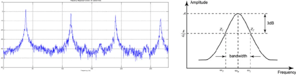
The energy dissipated by the layers was analysed further using a Matlab code to capture the frequency response function (FRF) of the vibration measurements. A typical FRF for the flax and
Figure 3. Typical frequency response functions of composite (left) and the half-power bandwidth method for loss factor calculations (right) proposed by Gelfuso et al. [31].
Each peak in the FRF represented a frequency in which the system vibrated excessively. This function could be used to calculate Young’s modulus, loss factor and damping ratio at the different resonant frequencies of each specimen. The loss factor was firstly calculated using the half-power bandwidth, as described in ASTM E756. Using the response curve of each specimen, the resonant frequency was measured, and then the frequencies above and below (by a value of 3 dB) were measured, as shown in Figure 3 [31–33].
The modal loss factor (η) could then be calculated as the ratio of the half-power bandwidth to
the resonant frequency, η = . The loss factor was calculated for all specimens for the first
resonant frequency, and the similar pattern emerged as the damping ratio. The loss factor was then
calculated for the 2nd, 3rd and 4th resonant frequencies for each laminate and plotted.
The half-power bandwidth method was also used to calculate the damping ratio of each
specimen. The damping ratio was calculated as ξ = , as stated by Vanwallegham (2010). The
resonant frequencies were then used to calculate Young’s modulus using Equation 3.
=12 (3)
where and are the length (m) and density (kg⁄m3) of the composite beam, respectively. is the
resonance frequency (Hz) for mode (1,2, 3,…), is the composite beam thickness (m) in the
vibration mode, is the co-efficient for mode n, and is Young’s modulus (GPa).
3. Results and Discussions
3.1. Tensile Properties
The tensile results in Table 2 show that the carbon fibre laminate has the highest Young’s modulus of 25.353 GPa and the highest tensile strength of 503.27 MPa as expected [5,7]. There is no plastic region seen on the stress vs strain graph for any specimen, which shows that all manufactured composites are brittle. The laminate composed of flax fibres alone has Young’s modulus of 5.549 GPa and tensile strength of 101.66 MPa, matching similar studies by Nassiopoulos and Njuguna [34]. When an external flax layer is added to the composite, this decreases Young’s modulus considerably by 28.1%, and then two layers reduce it by 45%. This large decrease is because the external flax layer fails first as the flax has the lowest Young’s modulus, shortly followed by the carbon fibre layers.
Table 2. Tensile test results on Young’s modulus vs flax fibre content and the damping ratios calculated from frequency and time domain.
Specimen Average Young’s Modulus (GPa), Standard Deviation (%) Ultimate Tensile Strength (MPa), Standard Deviation (%) Damping Ratio from Bandwidth Method (%), Standard Deviation (%) Damping Ratio from Time Domain (%), Standard Deviation (%) [C/F2/ ± ]s 11.833 (9.06) 173.75 (5.80) 1.0544 (27.81) 0.2359 (12.18) [C/F2/C]s 11.735 (7.82) 224.40 (13.33) 1.1087 (25.89) 0.2460 (18.36) [F2/C2]s 13.946 (2.51) 297.41 (4.94) 1.6709 (28.57) 0.3939 (10.06) [F/C3]s 18.234 (3.75) 358.04 (3.58) 0.9779 (28.61) 0.3140 (8.33) Carbon Fibre 25.353 (12.91) 503.27 (10.37) 0.8703 (26.49) 0.203 (42.34) Flax 5.549 (3.82) 101.66 (1.61) 1.9180 (31.57) 0.5565 (5.66)
Another observation is the fact that although [F2/C2]s has the same flax fibre content as [C/F2/C]s,
it records an increased Young’s modulus and UTS of 18.83% and 32.54%. This may be due to the fact
that the [F2/C2]s laminate has four carbon fibre layers stacked on top of one another in the centre of
the laminate. This is due to the fibres aligning together and effectively becoming one strong carbon fibre layer as opposed to two small layers, which fail under a lower load. This shows that the closer the carbon layers are together, the stronger the composite becomes. It could also be seen that as the flax fibre content increases, a decrease in Young’s modulus and tensile strength is recorded, as shown in Figure 4, a pattern common in the literature [7,9,35]. It is also interesting to note that when
comparing the [C/F2/C±45]s and [C/F2/C]s laminates, they both have a very similar Young’s modulus
property that is within 1% of each other, although [C/F2/C]s has a much higher tensile strength, as
demonstrated in Figure 4.
.
Figure 4. The Young’s modulus (a) and the ultimate tensile strength (b) for investigated composite materials.
The [C/F2/C]s laminate withstands a 61% higher loading than the [C/F2/C± ]s laminate (Figure
5). This is expected as more fibres are aligned in their strongest position as opposed to the tensile force and thus withstand a greater loading condition. A decrease in the strength of a composite may also be due to poor fibre matrix bonding that can lead to non-uniform stress transfer, excessive movement of the fibres within the matrix, which can all lead to premature failure of the composites [36]. Besides, Zhang et al. [36] investigated the influence of hybrid ratio and stacking sequence on the unidirectional glass and flax fibre-reinforced hybrid composites and found an improved fracture toughness and interlaminar shear strength than the glass fibre-reinforced composites. This improved performance in the present study is associated with excellent hybrid performance and hybrid interface.
Figure 5. The comparison of stress-strain relationship for [C/F2/C]s laminate against [C/F2/C± ]s
laminate.
3.2. Damage Characterisation
The flax and carbon fibre samples consistently break perpendicular to the tensile load applied on the beam, indicating distributed loading for every layer of the laminate, leading to simultaneously shared tensile load. A few fibres are observed under microscopy to be pulled out of the matrix, most likely the first fibre to fail. During the tensile testing, external fibres in hybrid composites rupture first (snapped), followed by the entire specimen failure. It appears that once the external fibres begin to fail, this then leads to stress concentrations in that part of the specimen. This weakens the specimen, and rupture occurs within a few seconds after the first fibre’s audible snap. This occurs more frequently when the external layers are flax and, in some cases, the external layers begin to
delaminate just prior to rupture, as, for example, shown in the [F/C3]s sample in Figure 6. In the case
of the [F/C3]s sample, the outer layers clearly rupture first and begin to delaminate from the internal
layers since the external layer has a lower tensile strength than the internal layer, causing it to fail at a lower load and delaminate from the internal layers. It could also be seen that the rupture of this specimen is angular, which suggests that the outer edge of the specimen fails first. This specimen is characterised to have an edge delamination/angled/bottom (DAB) failure mode, according to ASTM D3039 [29]. Table 3 shows the failure modes of all specimens. It is interesting to note that near the fracture of the specimen, the surroundings fibres begin to change colour due to the heightened stress around that area. This is also seen in specimens A and B, as seen in Figure 5.
Table 3. Tensile test failure analysis of the composite specimens.
Specimen Test Number Mode of Failure *
[C/F2/C± ] s A LAB B LAT C AAT D LIT E LIT [C/F2/C]s A LMV B LMV C LMV D LGM E LGM [F2/C2]s A LAT B LMV C LAB D DMV E DAT [F/C3]s A AAT B AAB C AAT D AAT E DAB Carbon Fibre A LAT B LAT C LAT D LAT E LMV Flax A LAT B LIB C LIT D LIB
*R epresent failure mode as follows First Character codes: Angled (A), Edge delamination (D), Grip/tab (G), Lateral (L), Multi-mode (M); Second Character Codes: Inside grip/tab (I), At grip/tab (A), Gage (G), Multiple areas (M) and Various (V); Third Character codes: Bottom (B), Top (T), Left (L), Middle (M) and Various (V).
The internal carbon fibre layers are observed to be more prominent than the external flax layers. This is because the internal carbon fibre layers are able to withstand a higher load and will take a higher force before a fracture occurs, as noted earlier on. Manufacturing defects, such as an unequal spread of the epoxy resin or air getting inside the vacuum during or after infusion, are detrimental
to mechanical properties. The [F2/C2]s specimens consistently break at multiple locations on an equal
distribution of fibres and epoxy in the composites (Figure 6). The external flax layers are pulled away from the internal layer as it begins to fracture, whereas the internal carbon fibre layers remain intact. On viewing the specimen from the side, the external layers begin to delaminate from the internal layers (Figure 6).
Figure 6. Optical images of the damaged features for various composites studied. [F/C3]s showing
edge delamination and stress concentrations at failure points (a,b), as well as some signs of voids and fibres pull out (c); fracture in [C/F2/C±45]s samples (d,e), flax fibres extrusion in (f,g) and [C/F2/C]s
laminate (h) fracture and delamination.
For the flax laminate, the breaking occurs perpendicular to the tensile load applied on the beam, indicating the failure of simultaneous layers in the respective laminate under the same load condition.
[C/F2/C±45]s laminate shows that three out of the five specimens break unevenly through the layers of
the specimen. This may be caused by the internal ±45° layers failing first as they are not aligned in
a way to oppose the tensile force. This leads the surrounding layers to expand, causing one side to
fail early. The [C/F2/C]s laminate shows good load distribution between the fibre and matrix spread
of the whole specimen. It is noted that carbon fibres are prominent to flax ones in that the flax layers fail before the carbon fibres at a lower load, causing the composite to fail at a lower load than carbon fibre only composite (Figure 6). It can also be seen that the fracture is not linear across the whole specimen. This may have been caused by the internal flax layers failing in steps due to disruption nearer the outer layers of the specimen associated with the hybrid composite configuration.
3.3. Damping Properties
The damping testing results can be seen in Table 2 and in Figure 7 and clearly demonstrate that a relationship exists between the fibre content and damping ratio, whereby the damping ratio increases with the flax fibre content in the composites. It can also be seen that by adding one flax layer to the outside of a carbon fibre laminate, the damping ratio increases by 54.6% and two flax layers increase by 93.9%. This is mainly because the external layers dissipate the energy most, and therefore, where the external layers are flax, the composite exhibits damping properties similar to flax laminates, as also noted by Assarar et al. [21] and Li et al. [37]. However, Flynn et al. [7] found out that where the external layers were carbon fibre, this led to lower damping properties, so these laminates were not deemed necessary for this study. The effects of varying fibre orientation in our study were also
investigated by manufacturing a [C/F2/C]s laminate and a [C/F2/C±45]s laminate.
When comparing the effects of fibre orientation between [C/F2/C]s and [C/F2/C±45]s, there is a
very slight decrease in the damping ratio when the two ±45° layers are introduced. This is most
likely due to the fact that the [C/F2/C]s laminate has fibres alignment that is perpendicular to the mode
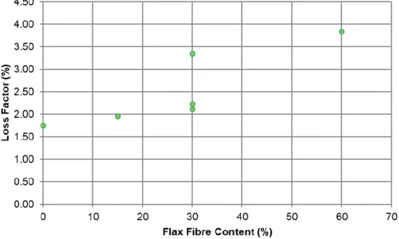
of vibration. This composite is able to absorb more energy from the vibration and thus has a higher damping ratio. This shows that the orientation of internal fibres in a laminate has much less effect on the damping properties than the external layer and provides an area for further research to explore the impact of the layer onto the properties. It can also be seen that the more the composite contains the flax fibre’s volume ratio, the higher loss factor is recorded, as displayed in Figure 8, using the average values of the loss factor for each sample. In addition, we have found out that an introduction
of the ±45° layers cause a 5.15% decrease in the loss factor, perhaps due to similar reasons as the
damping ratio discussed earlier on.
Figure 8. Loss factor versus flax fibre content for the composite specimens studied.
The loss factor decreases with the increase in the frequency, as shown in Figure 9. The flax laminate has the highest loss factor at the lowest frequency and has the lowest loss factor at its highest frequency. The lower the loss factor, it tends to have less effect from the increasing frequency. The damping ratio is then calculated using the first resonant frequency for all specimens, as presented in Table 2. In Figure 10, the results show a very similar pattern to the results achieved from the time domain; however, all values are higher by a factor of at least three. This was also found by Vanwallaghem [27], where values achieved by the bandwidth method were found to be ten times larger than the time-domain method. This can be attributed to the fact that an increase in the flax content causes an increase in the damping ratio (Figure 10) whilst also comparing with damping ratio achieved in the time domain.
These results agree with Assarar et al. [21], who noted that adding two flax layers outside a carbon laminate considerably enhanced its damping by 15–30%. Furthermore, these results align with those on glass fibre-reinforced composites in the literature. For instance, Prabhakaran et al. [38] also noted that the flax-reinforced composites had a 51% higher vibration damping than the glass fibre-reinforced composites. Follow up studies by Saidane et al. [39] on the stacking sequence of hybridized flax-glass fibre-reinforced composites reported that Young’s modulus and tensile strength of flax fibres were significantly increased by the addition of glass fibres. In addition, other similar studies on the effect of varying fibre orientation on carbon and glass fibres have also reported that the damping is at its maximum at a 60° fibre orientation [9,40,41]. When designing a composite material for a specific task, an engineer must first look at the requirements. For example, a material must be able to withstand a very high load and may also be subject to reciprocating motion, meaning that it must have high damping properties and high tensile strength. This type of material may not exist naturally; however, by combining materials like carbon fibre (high tensile strength and low damping properties) and natural flax fibre (high damping properties and low tensile strength), the desired material may be created, which exhibits properties of both materials.
Figure 10. Damping ratio vs flax fibre content using frequency domain and time domain.
One major advantage of using flax as reinforcement in hybrid epoxy-flax/carbon fibre-reinforced composites is its extremely high damping properties, as shown in this work. The damping results show an opposite relationship where an increase in the flax fibre content causes an increase in the damping ratio of the laminates. It is also shown that adding an external flax layer considerably enhances its damping ratio by 53.6% and by adding two layers increases it by 93.9%. This shows that the most important layer when it comes to damping properties is the external layers. This is effective where most of the energy is dissipated, so external layers, which are flax, lead to similar properties as flax materials. It is also observed that varying the fibre orientation of the internal layers has a very little effect on the damping ratio of the laminate. The damage caused by the tensile tests is then analysed for all ruptured specimens and shows that the delamination occurs between the flax and carbon fibre layers just prior to breaking point. It is also observed that the flax fibres begin to change colour around the area of breaking due to the heightened stress caused by the tensile load at this stage.
This study analysed the effects of varying stacking sequence and fibre orientation on hybrid carbon fibre/flax biocomposites. Various hybrid laminates were manufactured and then tested for tensile and damping properties, in accordance with ASTM D3039 and ASTM E756, respectively. The tensile study found out that adding a flax layer to the external layers of carbon fibre laminate reduced Young’s modulus by 28.1% for one layer and 45% for two layers. This was attributed to the flax fibres failing first, which then, in turn, caused the carbon fibres to fail at a reduced load shortly afterwards.
It was also found out that when the fibre orientation of the internal layer of [C/F2/C]s wasreplaced
with the two ±45° layers, this had a very little effect on Young’s modulus but reduced the UTS by
61%. This was due to the fact that in the [C/F2/C]s laminate, there were more fibres aligned so that
they opposed the tensile load in their strongest position. A relationship was observed when the flax fibre content of the laminate was increased, resulting in a decrease in Young’s modulus and the UTS. The Young’s modulus of each laminate was noted to decrease with the increasing frequency. The decrease appeared to be constant with all specimens, which showed that the changing frequency had the same effect, no matter what the stacking sequence of the laminate was. This could be attributed to the fact that as each specimen vibrates more excessively, the specimen will tend to break under a lower load due to the heightened stress. The study results showed that one major advantage of using flax as reinforcement in hybrid epoxy-flax/carbon fibre-reinforced composites is its extremely high damping properties up to 53.6%, and by adding two layers to the composite, it increased the damping ratio by 93.9%. It is shown that the most important layers when it comes to damping properties are the external layers.
Author Contributions: Conceptualization, J.N.; methodology, G.F. and J.N.; software, G.F. and J.N.; validation, G.F. and J.N.; formal analysis, G.F. and J.N.; investigation, G.F. and J.N.; resources, J.N.; data curation, G.F. and J.N.; writing—original draft preparation, G.F. and J.N.; writing—review and editing, G.F. and J.N.; visualization, G.F. and J.N.; supervision, J.N.; project administration, J.N.; funding acquisition, J.N. All authors have read and agreed to the published version of the manuscript.
Funding: This research received no external funding.
Acknowledgments: The authors would like to acknowledge the technical support of Mr Allan McPhersons & Mr David Smith in the samples’ preparations and mechanical testing.
Conflicts of Interest: The authors declare no conflict of interest.
References
1. Masuelli, M.A. Introduction of fibre-reinforced polymers- polymers and composites: Concepts, properties and processes. In Fiber Reinforced Polymers-The TechnologyApplied for Concrete Repair; IntechOpen: London, UK, 2013.
2. Njuguna, J. Lightweight Composite Structures in Transport: Design, Manufacturing, Analysis and Performance; Elsevier Woodhead Publishing: Amsterdam, The Netherlands, 2016.
3. Rueppel, M.; Rion, J.; Dransfeld, C.; Fischer, C.; Masania, K. Damping of carbon fibre and flax fibre angle-ply composite laminates. Compos. Sci. Technol. 2017, 146, 1–9.
4. Le Guen, M.J.; Newman, R.H.; Fernyhough, A.; Emms, G.W.; Staiger, M.P. The damping- modulus relationship in flax/carbon fibre hybrid composites. Compos. B2016, 89, 27–33.
5. Vanwalleghem, J.; de Baere, I.; Huysman, S.; Lapeire, L.; Verbeken, K.; Nila, A., Vanlanduit, S.; Loccufier, M.; van Paepegem, W. Effective use of transient vibration damping results for non-destructive
measurements of fibre-matrix adhesion of fibre-reinforced flax and carbon composites. Polym. Test. 2016, 55, 269–277.
6. Dhakal, H.; Zhang, Z.; Guthrie, R.; MacMullen, J.; Bennett, N. Development of flax/carbon fibre hybrid composites for enhanced properties. Carbohydr. Polym.2013, 96, 1–8.
7. Flynn, J.; Amiri, A.; Ulven, C. Hybridized carbon and flax fiber composites for tailored performance. Mater. Des.2016, 102, 21–29.
8. Bos, H.; van Den Oever, M.J.; Peters, O. Tensile and compressive properties of flax fibres for natural fibre reinforced composites. J. Mater. Sci. 2002, 37, 1683–1692.
9. Berthelot, J.; Sefrani, Y. Damping analysis of unidirectional glass and Kevlar fibre composites. Compos. Sci. Technol.2004, 64, 1261–1278.
10. Mahmoudi, S.; Kervoelen, A.; Robin, G.; Duigou, L.; Daya, E.; Cadou, J. Experimental and numerical investigation of the damping of flax/epoxy composite plates. Compos. Struct.2019, 208, 426–433.
11. Cheour, K.; Assarar, M.; Scida, D.; Ayad, R.; Gong, X. Effect of stacking sequences on the mechanical and damping properties of flax glass fiber hybrid. J. Renew. Mater. 2019, 7, 877–889.
12. Cheung, H.; Ho, M.; Lau, K.; Cardona, F.; Hui, D. Natural fibre-reinforced composites for bioengineering and environmental engineering applications. Compos. B2009, 40, 655–663.
13. Nabi Saheb, D.; Jog, J.P. Natural fiber polymer composites: A review. Adv. Polym. Technol.1999, 18, 351–363. 14. Faruk, O.; Sain, M. Biofiber Reinforcements in Composite Materials; Elsevier: Amsterdam, The Netherlands, 2014. 15. Charlet, K.; Jernot, J.; Eve, S.; Gomina, M.; Bréard, J. Multi-scale morphological characterisation of flax:
From the stem to the fibrils. Carbohydr. Polym.2010, 82, 54–61.
16. Le Duigou, A.; Davies, P.; Baley, C. Environmental impact analysis of the production of flax fibres to be used as composite material reinforcement. J. Biobased Mater. Bioenergy2011, 5, 153–165.
17. Zhu, J.; Zhu, H.; Njuguna, J.; Abhyankar, H. Recent development of flax fibres and their reinforced composites based on different polymeric matrices. Materials2013, 6, 5171–5198.
18. Kalia, S.; Dufresne, A.; Cherian, B.M.; Kaith, B.S.; Avérous, L.; Njuguna, J.; Nassiopoulos, E. Cellulose-Based Bio- and Nanocomposites: A Review. Int. J. Polym. Sci. 2011, 2011, 207–231.
19. Ameur, B.M.; El Mahi, A.; Rebiere, J.; Abdennadher, M.; Haddar, M. Damping analysis of unidirectional carbon/flax fiber hybrid composites. Int. J. Appl. Mech.2018, 10, 1850050.
20. Assarar, M.; Zouari, W.; Ayad, R.; Kebir, H.; Berthelot, J. Improving the damping properties of carbon fibre reinforced composites by interleaving flax and viscoelastic layers. Compos. B.2018, 152, 248–255. 21. Assarar, M.; Zouari, W.; Sabhi, H.; Ayad, R.; Berthelot, J. Evaluation of the damping of hybrid carbon-flax
reinforced composites. Compos. Struct.2015, 132, 148–154.
22. Van de Weyenberg, I.; Ivens, J.; de Coster, A.; Kino, B.; Baetens, E.; Verpoest, I. Influence of processing and chemical treatment of flax fibres on their composites. Compos. Sci. Technol.2003, 63, 1241–1246. 23. El-Hafidi, A.; Gning, P.; Piezel, B.; Belaïd, M.; Fontaine, S. Determination of dynamic properties of flax
fibres reinforced laminate using vibration measurements. Polym. Test.2017, 57, 219–225.
24. Avril, C.; Bailly, P.A.; Njuguna, J.; Nassiopoulos, E.; Larminat, D.A. Development of flax-reinforced bio-composites for high-load bearing automotive parts. In Proceedings of the European Conference on Composite Materials (ECCM), Venice, Italy, 24–28 June 2012.
25. Fan, J.; Nassiopoulos, E.; Brighton, J.; de Larminat, A.; Njuguna, J. New structural biocomposites for car applications. In Proceedings of the Anonymous Society of Plastics Engineers—EUROTEC 2011
Conference, Barcelona, Spain, 14–15 November 2011.
26. Akampumuza, O.; Wambua, P.M.; Ahmed, A.; Li, W.; Qin, X.H. Review of the applications of biocomposites in the automotive industry. Polym. Compos.2017, 38, 2553–2569.
27. Vanwalleghem, J. Study of the Damping and Vibration Behaviour of Flax-Carbon Composite Bicycle Racing Frames. Master’s Thesis, Ghent University, May, 2010.
28. La Raquette de Tennis en Composite de lin—Le lin ct Nature. Available online: https://www.lelin-cotenature.fr/FR/Une-raquette-de-tennis-legere-et-confortable-46.html (accessed on 4 April 2020). 29. ASTM International. Standard Test Method for Tensile Properties of Polymer Matrix Composite Materials;
ASTM D3039; ASTM International: West Conshohocken, PA, USA, 2008.
30. ASTM International. Standard Test Method for Measuring Vibration-Damping Properties of Materials; ASTM E756; ASTM International: West Conshohocken, PA, USA, 2010.
31. Gelfuso, M.V.; Thomazini, D.; de Souza, J.C.; Lima, J.; de Juliano, J. Vibrational analysis of coconut fiber-PP composites. Mater. Res.2014, 17, 367–372.
32. Banerjee, J.R.; Njuguna, J.; Morishima, R.; Perera, M.; Cheung, C. Free Vibration analysis of a three-layered sandwich beam using theory and experiment. In Proceedings of the 47th
AIAA/ASME/ASCE/AHS/ASC Structures, Structural Dynamics, and Materials Conference, Newport, Rhode Island, USA, 1–4 May 2006.
33. Banerjee, J.R.; Cheung, C.W.; Morishima, R.; Perera, M.; Njuguna, J. Free vibration of a three-layered sandwich beam using the dynamic stiffness method and experiment. Int. J. Solids Struct. 2007, 44, 7543–7563.
34. Nassiopoulos, E.; Njuguna, J. Thermo-mechanical performance of poly (lactic acid)/flax fibre-reinforced biocomposites. Mater. Des.2015, 66, 473–485.
carbon fiber dispersion on the low-velocity impact performance of woven flax-carbon hybrid composites. J. Compos. Mater.2019, 53, 1717–1734.
36. Zhang, Y.; Li, Y.; Ma, H.; Yu, T. Tensile and interfacial properties of unidirectional flax/glass fiber reinforced hybrid composites. Compos. Sci. Technol.2013, 88, 172–177.
37. Li, Y.; Cai, S.; Huang, X. Multi-scaled enhancement of damping property for carbon fiber reinforced composites. Compos. Sci. Technol.2017, 143, 89–97.
38. Prabhakaran, S.; Krishnaraj, V.; Zitoune, R. Sound and vibration damping properties of flax fiber reinforced composites. Procedia Eng. 2014, 97, 573–581.
39. Saidane, E.H.; Scida, D.; Assarar, M.; Sabhi, H.; Ayad, R. Hybridisation effect on diffusion kinetic and tensile mechanical behaviour of epoxy based flax glass composites. Compos. A2016, 87, 153–160. 40. Hadi, A.; Ashton, J. Measurement and theoretical modelling of the damping properties of a
uni-directional glass/epoxy composite. Compos. Struct.1996, 34, 381–385.
41. Njuguna, J.; Su, H.; Cheung, C.W.; Banerjee, J.R. The influence of ply orientation on the free vibration of composite beams. In Proceedings of the UNSW 2002 Conference, Sydney, Australia, 21–25 July 2002; pp. 307–314.
© 2020 by the authors. Licensee MDPI, Basel, Switzerland. This article is an open access article distributed under the terms and conditions of the Creative Commons Attribution (CC BY) license (http://creativecommons.org/licenses/by/4.0/).


![Figure 5. The comparison of stress-strain relationship for [C/F2/C] s laminate against [C/F2/C ± ] s laminate](https://thumb-us.123doks.com/thumbv2/123dok_us/843107.2607223/9.892.166.738.111.461/figure-comparison-stress-strain-relationship-c-laminate-laminate.webp)

![Figure 6. Optical images of the damaged features for various composites studied. [F/C3] s showing edge delamination and stress concentrations at failure points (a,b), as well as some signs of voids and fibres pull out (c); fracture in [C/F2/C ±45](https://thumb-us.123doks.com/thumbv2/123dok_us/843107.2607223/11.892.123.772.425.817/figure-optical-damaged-features-composites-delamination-concentrations-fracture.webp)