Vanguard Managed Solutions
Vanguard Applications Ware
SNA Feature Protocols
Notice
©2003 Vanguard Managed Solutions, LLC 575 West Street
Mansfield, Massachusetts 02048 (508) 261-4000
All rights reserved Printed in U.S.A.
Restricted Rights Notification for U.S. Government Users
The software (including firmware) addressed in this manual is provided to the U.S.
Government under agreement which grants the government the minimum Òrestricted rightsÓ in the software, as defined in the Federal Acquisition Regulation (FAR) or the Defense Federal Acquisition Regulation Supplement (DFARS), whichever is applicable. If the software is procured for use by the Department of Defense, the following legend applies:
Restricted Rights Legend
Use, duplication, or disclosure by the Government is subject to restrictions as set forth in
subparagraph (c)(1)(ii) of the
Rights in Technical Data and Computer Software clause at DFARS 252.227-7013.
If the software is procured for use by any U.S. Government entity other than the Department of Defense, the following notice applies:
Notice
Notwithstanding any other lease or license agreement that may pertain to, or accompany the delivery of, this computer software, the rights of the Government regarding its use, reproduction, and disclosure are as set forth in FAR 52.227-19(C).
Notice (continued)
Proprietary Material
Information and software in this document are proprietary to Vanguard Managed Solutions, LLC (or its suppliers) and without the express prior permission of an officer, may not be copied, reproduced, disclosed to others, published, or used, in whole or in part, for any purpose other than that for which it is being made available. Use of software described in this document is subject to the terms and conditions of the Software License Agreement.
This document is for information purposes only and is subject to change without notice.
To comment on this manual, please send e-mail to [email protected] Part No. T0101-07, Rev H
Publication Code DS
First Printing November 1998
Contents
Chapter 1. Introduction
Other Information ... 1-4 Hardware and Software Requirements ... 1-5 Technical Overview ... 1-6 Theory of Operation ... 1-10 SNA Overview ... 1-10 How the AS/400 5494 Communications Server Feature Works ... 1-13
Chapter 2. Configuration
Configuration Planning and Network Topologies ... 2-2 Configuration Examples ... 2-4 Configuration Example #1 ... 2-5 Configuration Example #2 ... 2-8 Configuration Example #3 ... 2-11 Configuring the AS/400 Host System ... 2-14 AS/400 Host System Configuration Requirements ... 2-15 AS/400 Configuration Status Display ... 2-32 Configuring the Vanguard Node ... 2-34 Configuring the LAN Control Menu ... 2-35 Configuring the APPN Table ... 2-36 Configuring the Node Record ... 2-37 Configuring Port Records ... 2-39 Configuring Station Records ... 2-48 Configuring 5394 Controllers ... 2-56
Chapter 3. Statistics and Troubleshooting
Statistics/status Screens for the AS/400 5494 Communications Server Feature 3-2 Troubleshooting and Diagnostics ... 3-6 Viewing Traces ... 3-7
Chapter 1
Introduction
Overview
Introduction This manual describes the AS/400 5494 Communications Server feature as
implemented for Vanguard products. This feature works with the OS/400 operating system, which is used primarily on AS/400 systems, and may also be found on System/36, System/38, and other systems.
About This Guide The primary purpose of this document is to provide the information you need to configure the AS/400 5494 Communications Server feature for your network. Because networks are unique to each location, the information in this guide is generalized. You should study carefully the Configuration Application examples in Chapter 2, which present a variety of network architectures.
References in this guide to specific IBM equipment also includes compatible equipment from other vendors, unless otherwise specified. You should also remember that references to the AS/400 are also applicable to other systems using the OS/400 operating system.
Before You Begin You should have a basic understanding of the OS/400 system and IBM or compatible remote controllers (particularly the 5394- and 5494-type controllers). You need to know how to configure the OS/400 using definition statements. You also need to know how to configure 5394-type controllers and their attached devices, such as displays and printers.
The AS/400 5494 Communications Server feature
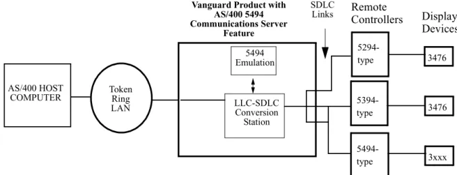
The AS/400 5494 Communications Server feature makes a Vanguard function as a 5494 LAN communications server for OS/400 host systems with attached 5394-type (including 5394-, 5294- and compatible-type) remote controllers.
Figure 1-1 is a diagram illustrating how this feature would be used in a network. Vanguard products with this feature emulate 5494-type communication between an AS/400 Host system and the remote controller (using the “Emulation” module). This feature lets you connect 5394-type controller devices to host AS/400 computers using a LAN connection (Token Ring or Ethernet), rather than an SDLC link. You can mix 5494- and 5394-type controllers on the same LAN interface with the host
Figure 1-1. The AS/400 5494 Communications Server Feature
Note
You may require additional memory in Vanguard products, serial communications interfaces, LAN and WAN interfaces, or special cables for this feature.
IBM-Compatible Equipment
This feature operates with IBM-compatible equipment; IBM model numbers have been used to identify particular types or models of equipment. Not all manufacturers’ units have been tested for interoperability. If you experience problems in interfacing non-IBM equipment, refer to your documentation or discuss the issue with your supplier.
Related Vanguard Documentation
Refer to these related Vanguard documents for additional information: • Vanguard Configuration Basics Manual (Part No. T0113) • Vanguard Basic Protocols Manual (Part No. T0106) • Vanguard SNA Feature Protocols Manual (Part No. T0101)
• Vanguard Applications Ware Alarms and Reports Guide (Part No. T0005) • Vanguide Documents on the Vanguard CD-ROM
AS/400 HOST
COMPUTER Token Ring LAN
Vanguard Product with AS/400 5494 Communications Server Feature LLC-SDLC Conversion Station 3476 5394-type 5494 Emulation SDLC Links 3476 5294-type 3xxx 5494-type Display Devices Remote Controllers
Related Vendor Documentation
The documents listed below provide additional information about the SNA Architecture, the AS/400 Host system, and remote controller units.
IBM
• APPN Architecture and Product Implementations Tutorial
(Part No. GG24-3669-00)
• 5494 Remote Control Unit Functions Reference (Part No. SC30-3533-04)
• The X.25 Interface for Attaching SNA Nodes to Packet Switched Data Networks General Information Manual
• AS/400 Communication Definitions Examples (Part No. GG24-3449-00)
Perle
• Perle 394 Hardware Setup Guide (Part No. 95-1032-01) • Perle 394 IOPV-8-E Twinax Controller Card User’s Guide
(Part No. 95-1053C0)
Internet/Web Addresses
The following Internet/Web (WWW) addresses have relevant information:
• Vanguard Managed Solutions
http://www.vanguardms.com
• I BM
AS/400 information:
http://as400bks.rochester.IBM.com/bookmgr/v4r2frm.htm To reach AS/400 manuals:
- Select category Bookshelves for V4R2. - Select 5 Host Communications.
- Select Communications Configuration SC41-5401. APPN Implementation Workshop:
http://www.networking.ibm.com/app/aiwhome.htm
• Perle
Other Information
Software Licensingfor this Feature
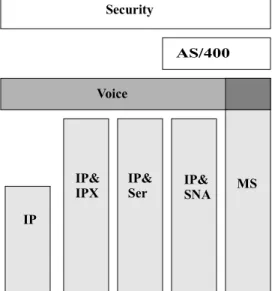
This feature is licensed as an optional part of the Vanguard Applications Ware. This feature license is shown as the AS/400 block in Figure 1-2. You also need one of the base Vanguard Applications Ware licenses. The IP&SNA (Internet Protocol and SNA Features) license or the MS (Multi-Service) license can be used as the
necessary base license with the AS/400 license. The AS/400 5494 Communications Server feature can also be used on Vanguard products that have Voice and Security features. However, the Voice and Security features do not provide the necessary base license.
Figure 1-2. AS/400 5494 Communications Server Feature License with Base Feature Combinations
Trademarks The following are trademarks or registered trademarks of their respective companies or organizations:
• Vanguard and Vanguide are trademarks or registered trademarks of Vanguard Managed Solutions, LLC.
• IBM is the trademark or registered trademark of the International Business Machines Corporation.
• Perle is the trademark or registered trademark of Perle Corporation.
Alarms and Reports
Refer to the Vanguard Applications Ware Alarms and Reports Manual
(Part Number T0005) for details on alarms and reports generated by this feature.
Voice Security AS/400 MS IP& IP& IP& IP
Hardware and Software Requirements
Hardware and Software Requirements
OS/400 OperatingSystem and AS/400 Host Computer
This feature works with the OS/400 operating system, version V3R2 or later. The OS/400 runs on the IBM AS/400 (or compatible) Host computer system. Other computer systems (such as System/36 and System/38) may operate under OS/400, and can be configured to support this feature.
This feature is not used with IBM and IBM-compatible main-frame (such as the 30x0) host computer systems.
Maximum number of Controllers Supported with this feature
The recommended maximum number of remote controllers (5494-type, 5394-type, and 5294-type) are as follows:
• Vanguard 6560 (with 16 MB of memory) = 40 controllers • Vanguard 6520 (with 8 MB of memory) = 10 controllers
• Vanguard 6400 Series (with 16 MB of memory) = 15 controllers
These recommended maximum controller numbers assume a maximum of four displays and printers per controller. Fewer controllers are supported if more than four display or printer units are attached to the controllers.
Note
You may have to add additional memory to your Vanguard products to support your intended network architecture and size.
Controllers and Attached Devices Supported
This feature works with controllers made by different manufacturers. These controllers and their associated display units and printers include:
• IBM 5394 Cluster Controller
Display: 5291, 3476, 3180. Printer: 4224 • IBM 5294 Cluster Controller
Display: 5291, 3476, 3180 • Perle 593 Cluster Controller
Technical Overview
Technical Overview
Introduction This section contains a brief technical overview of the AS/400 5494
Communications Server feature. You should remember that this feature makes non-5494-type controllers appear to be 5494-type controllers to the OS/400 system through emulation.
Major Features The AS/400 549 Communications Server feature has these primary characteristics:
Characteristic Description or Benefit
Eliminates native AS/400 Host system connection restrictions for 5294- and 5394-type controllers to a LAN.
The AS/400 treats the 5494 emulation by the Vanguard as a 5494-type connection, and allows non-5494-type controllers to be attached to the AS/400 through a LAN connection (Token Ring or Ethernet).
Supports both 5394-type and 5294-type controllers.
The AS/400 5494 Communications Server feature works with 5394- and 5294-type controllers that use a 5250-type of data stream. Replaces multiple point-to-point SDLC
or X.25 connections with a single LAN connection.
The AS/400 5494 Communications Server feature allows you to change your network design from point-to-point links to a single LAN connection between the AS/400 and the Vanguard. Emulates LU6.2 connectivity for
5394-type devices attached to the AS/400.
The AS/400 can use LU6.2 connectivity to communicate with 5394-type
controllers. The native LU4/7 packets from 5394-type controllers are encapsulated inside LU6.2 packets for upstream communication. In the downstream direction, the LU6.2 packets are stripped off, leaving LU4/7 packets for the
5394-type controller. Operates with existing Vanguard
Applications Ware that performs the LLC-SDLC conversion.
This feature is integrated into existing Vanguard Applications Ware so you can take advantage of the LLC-SDLC conversion choices, including HPAD/ TPAD and TPAD/LLC-SDLC. Supports WAN networks (X.25 or
Frame Relay).
The AS/400 5494 Communications Server can be used in multiple Vanguard products to create large-scale WAN networks using X.25 or Frame Relay.
Technical Overview
Eliminates Standard OS/400 Network
Limitations
The OS/400 operating system is used on the AS/400, and requires that the controller type and model be identified in the OS/400. The OS/400 does not accept certain network configurations, such as LAN connections for 5294- and 5394-type controllers. The OS/400 only allows non-5494-type controllers to be attached through SDLC (or X.25) connections. If the remote control unit and model and type is not compatible with a LAN connection in its native mode, the OS/400 terminates the configuration effort. For example, certain equipment, such as the
5394-type controller, support SDLC connections, but cannot be appended to a Token Ring LAN resource on the AS/400.
With the AS/400 5494 Communications Server feature, you can a Token Ring or Ethernet LAN into your network.
Supports Multiple Controller Types
This feature works with 5294- and 5394-type controllers (5250-type data stream). You can have a mix of 5294-type, 5394-type, and 5494-type controllers in the same network, with all controllers appearing to be 5494-type units to the AS/400.
SDLC Conversion The AS/400 5494 Communications Server feature supports conversion of the SDLC protocol typically used by 5294-type and 5394-type controllers to communicate with the AS/400, into QLLC (using the LLC-SDLC conversion in Vanguard Applications Ware). This QLLC can be routed through a Token Ring or Ethernet LAN connection to the AS/400. LAN connections typically offer higher speeds and greater
throughput as compared to SDLC-type connections.
LU6.2/PU2.1 Connectivity
This feature emulates the LU6.2/PU2.1 connectivity used between the AS/400 and 5494-type controllers. The Vanguard software encapsulates LU4/LU7 data packets from the PU Type 2 controllers inside LU6.2 packets for the AS/400, and can separate out the LU4/LU7 data packets from LU6.2 packets for the downstream PU Type 2 controllers.
Integrated into Existing SNA Features
The AS/400 5494 Communications Server operates with the other Vanguard SNA features, including SDLC-to-LLC conversion, HPAD-TPAD functionality, and QLLC conversion. You need to have the necessary IP/SNA or Multi-Service licenses to utilize these existing features.
X.25 or Frame Relay WAN Support
The AS/400 5494 Communications Server feature can be used with Vanguard X.25 or Frame Relay WAN features to create large-scale networks. You can configure one central Vanguard unit to perform the 5494-conversion, and at the same time function as an X.25 node or as a Frame Relay Interface (FRI).
Technical Overview
Other Vanguard SNA Features Supported
This table highlights other Vanguard features which can be used in with the AS/400 5494 Communications Server.
Feature Description Benefits
Access support for PU Type 2 and Type 2.1
Compatibility with existing SNA PU (Physical Unit) types. In a PU Type 2.1 environment, peer-to-peer nodes can communicate transparently across a Frame Relay SVC or across X.25.
• Full device support • Support of hierarchical
and peer-to-peer SNA networks.
Local Polling
(also called Spoofing)
Local polling means that polls from a host resource site receive a local response on one side of a call. Polls at the remote site of the call are generated in the end user device, and are automatically answered. This is supported in a serial environment (SDLC spoofing) and in an SNA LAN environment (LLC2 Local Termination).
• Bandwidth requirements are reduced.
• Faster access to host resources.
SDLC-to-LLC Conversion: LAN (Token Ring and Ethernet)
Full conversion options are available for: • SDLC-to-LLC
• LLC-to-SDLC
A variety of media at central site and remote site locations are supported including STP, UTP, coax, and fiber. • Flexibility • Reduced costs • Ease of operations SDLC-to-LLC2 Conversion: RFC1490
RFC1490 is a standard that defines transporting multiple protocols, including LLC, over Frame Relay.
• Interoperability with other RFC1490-compliant vendors.
• Standard interface method.
• Consolidation of PUs over single DLCI/PVC for reduced bandwidth requirements. Data Connection/
Protection (DCP)
This feature is compatible with the Data Connection/ Protection feature.
Data connection maintains a virtual connection if the link fails. When the primary line drops, the internal SVC call is maintained while the connection is re-routed across a dial backup network. When the connection is reestablished, data traffic is resumed. Data protection maintains data integrity across the network using OSI transport layer 4 interfacing.
Note
You can apply Data/Connection Protection to any combination of SDLC or LLC2 circuits.
• Session protection • No loss of user data • Data integrity
Traffic Prioritization Four levels of network traffic priorization are available: Expedite, High, Medium, and Low.
• Critical application support
Technical Overview
Dual Token Ring Two Token Ring cards are used to increase LLC2/ SDLC conversion capacity.
• Offers backup capability • Flexible network
management. SNA Dial on Demand PU and LU sessions are maintained between data
transmissions; the network is used only when data is ready to send.
• Significant reduction in network costs
Theory of Operation
Theory of Operation
Introduction The theory of operation presented below provides a basic description of how this feature has been implemented in Vanguard products. Reference is made to SNA terms as necessary.
SNA Overview
What Is SNA? SNA (Systems Network Architecture) is an IBM-defined data communications architecture that is widely used in small-, medium-, and large-scale networks. SNA specifies how hardware and software entities are connected to each other, and how they communicate with each other. SNA supports both hierarchical (top-to-bottom) and peer-to-peer network topologies.
SNA contains seven different layers that specify the formats and protocols used for communication. These layers range from the highest application layer to the lowest physical layer:
• Transaction Services (applications such as data base access and document interchange)
• Presentation Services (network resource management, session presentation and application management)
• Data Flow Control (data flow synchronization and exchange) • Transmission Control (data exchange pacing and encryption tasks)
• Path Control (data routing between source and destination and network data traffic control)
• Data Link Control (data transmission between adjacent nodes, using Channel Connect, SDLC, or Token Ring protocols).
• Physical Control (physical and electrical connections between adjacent nodes).
SNA has evolved into an Advanced Peer-to-Peer Networking (APPN) design, where multiple APPN nodes with attached peripheral nodes can interact with each other.
SNA Terminology The key SNA terms are: • End User
• Logical Unit (LU) • Physical Unit (PU)
• System Services Control Point (SSCP) • Network Addressable Unit
• Session
• SNA Data Formats
Theory of Operation
End User End Users typically interact with the SNA architecture through I/O devices such as printers and display stations. End users generally work with applications and application data, and are the final source and destination of such data. The AS/400 5494 Communications Server feature allows the AS/400 to communicate with end users who are connected to 5294- and 5394-type controller units.
Logical Unit (LU) SNA defines a set of LU (logical unit) types, ranging from 1 through 7. Each LU type has certain characteristics and features, which are associated with the SNA stack. The common LU types are:
• LU4 = Printer • LU7 = Display
• LU6.2 = LU-to-LU communication
LUs are “ports” through which end-users communicate with each other and the host computer. They are defined as network addressable software units. Data packet structures are associated with the LU types, which support the SNA communications protocols. The LU6.2 type supports the most advanced communications interface between two network nodes.
The AS/400 can only handle LU7 and LU4 communications for 5394-type
controllers, but uses LU6.2 data packets with the 5494-type controllers. The AS/400 5494 Communications Server feature encapsulates the LU4 and LU7 packets inside LU6.2 packets, which can then be transferred through Token Ring, Ethernet, or Frame Relay (RFC1490) networks to the AS/400.
Physical Unit (PU) SNA defines a set of PU (physical unit) types, which characterize attributes and network functionality of devices. PUs in the SNA world are defined as the software controlling the physical devices. PUs have the following features:
• Are network-addressable nodes • Control the physical interface
• Support and control the Link Level Protocols (such as SDLC or LLC2) • Provide network access for end users.
The primary PU types are: • Host node (PU Type 5)
• Communications Controller node or Front End Processor (FEP) node (PU Type 4)
• Cluster Controller node (PU Type 2)
Theory of Operation
System Service Control Point (SSCP)
The SSCP is the central control point within an SNA network, which manages and allocates the various network resources. The SSCP “domain” defines all the components (network addressable units) controlled by that SSCP. Each host system has one or more SSCPs, each of which has its own domain.
LSCP (Local Service Control Points) control the resources within the local node only, and may be within the domain of an SSCP.
Network
Addressable Unit (NAU)
Network Addressable Units are entities which are recognized and controlled by the network. These include:
• Logical Units (LUs) • Physical Units (PUs)
• System Services Control Points (SSCPs)
Each NAU has a unique address, and are the source or destination of data through the Path Control Network (defined as the bottom three of the seven SNA levels). The Path Control Network includes the DLC and the physical layer.
Session A session is the logical connection between two NAUs, which uses specified SNA protocols and allocates the resources required. These resources include the network paths, buffers, and protocols required for the session. Common session types are LU-to-LU, SSCP-to-PU, and SSCP-to-LU.
SNA Data Formats SNA has a number of different data formats which are used by the NAUs, Path Control layer, and Data Link Control layer to exchange information. These data formats consist of one or more headers, with accompanying messages. Each layer sets bits in specific headers.
The LU4/7 and LU6.2 data formats are seen by the AS/400 as different data formats, and handled differently. With the AS/400 5494 Communications Server feature, the Vanguard emulates the LU6.2 format for data packets from non-5494 controllers in the upstream direction, and separates the LU4/7 format packets from the LU6.2 packets in the downstream direction. This emulation process is discussed in more detail in the next section.
Theory of Operation
How the AS/400 5494 Communications Server Feature Works
Data Formats in theVanguard
The previous section ended with a brief description of how the AS/400 5494 Communications Server feature emulated the different LU data packets between the AS/400 and attached non-5494-type controllers. Now, let’s look a little closer at the data formats within the Vanguard with the communication server feature.
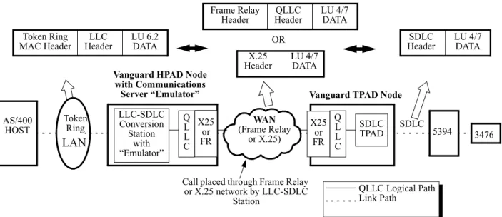
Figure 1-1 shows a simplified network and the changes in the data format as the packets pass through the network. The network consists of these elements:
• AS/400 Host computer • Token Ring LAN
• Vanguard node containing the AS/400 5494 Communications Server feature (“Emulator” in the LLC-SDLC Conversion Station box) which functions as an HPAD node
• Frame Relay WAN
• Remote Vanguard node which functions as a TPAD node • 5394-type Controller, with attached 3476 Display
The different data formats generated by the network components (LAN, WAN, and SDLC stages) are shown by hollow arrows.
Figure 1-3. Data format changes through Vanguard nodes in the
AS/400 HOST
Token Ring
LAN
Vanguard HPAD Node with Communications Server “Emulator” LLC-SDLC Conversion Station with “Emulator” WAN (Frame Relay or X.25) 5394 3476
Call placed through Frame Relay or X.25 network by LLC-SDLC Station SDLC TPAD Token Ring MAC Header LLC Header LU 6.2 DATA Q L L C Q L L C QLLC Logical Path Link Path
Vanguard TPAD Node
SDLC Header LU 4/7 DATA SDLC X25 or FR X25 or FR X.25 Header LU 4/7 DATA Frame Relay Header QLLC Header LU 4/7 DATA OR
Theory of Operation
When the AS/400 5494 Communications Server feature is installed in a Vanguard node (shown as “Emulator” in the figure), the LLC-SDLC Conversion Station can be configured to support the SDLC-to-LLC conversion for downstream SDLC 5394-type controllers. A key element in this SDLC-to-LCC conversion is the change in data format of the data frames.
As shown in Figure 1-3, this LLC-SDLC Conversion Station establishes a call to a downstream SDLC TPAD to which the 5394-type controller is attached. The Vanguard converts the PU Type 2 and LU4/LU7 commands and data frames received from the 5394-type controller into LU6.2 packets, and then sends these packets via LLC2 to the AS/400. In the downstream direction, LU6.2 frames from the AS/400 are converted by the Vanguard to LU4/LU7 frames before being sent to the 5394-type controller.
SNA Node Functionality
The AS/400 5494 Communications Server feature incorporates elements of the SNA node functionality into Vanguard products. SNA nodes have evolved to allow peer-to-peer networking and support PU2.1/LU6.2 functions. However, Vanguard nodes that have this Communications Server feature does not have the full set of SNA node features. What is provided is limited LU6.2/PU2.1 functionality to support non-5494-type controllers through non-5494-type emulation.
When performing conversion from SDLC to LLC for a 5394-type controller, the LLC-SDLC Conversion Station appears to the AS/400 as a 5494-type Low Entry Networking node. The LLC-SDLC Conversion Station has a configurable Local Control Point Name. During LLC2 (Logical Link Control Type 2) Link Activation, the LLC-SDLC Conversion Station and the AS/400 go through an Exchange Identifier (XID) negotiation. In this negotiation, parameters like Local Control Point and ID Number/ID Block are passed in the XID Format 3 exchanges.
AS/400-to-Controller Session Start-Up Sequence
Figure 1-4 shows an example of the startup sequence of a typical LLC-SDLC Conversion Station for a “5494” Link Station Type. “5494” is used for both 5494-type controllers and 5494-emulated controllers (via the AS/400 5494 Communications Server feature). This start-up sequence establishes a session between the AS/400 and the controller through the Vanguard nodes.
Note
This example shows the call placed downstream from the Vanguard connected to the AS/400. The call could have been configured to come from the Vanguard connected to the controller. In that case, the sequence would be different. Once the XID negotiation succeeds and LLC2 Link Activation is successfully established, the LLC-SDLC Conversion Station establishes the call to the SDLC TPAD port of the remote Vanguard unit. If the remote call is successfully
established, then the LLC-SDLC Conversion Station BINDs an LU6.2 session with the AS/400. This is referred to as the Controller Conversation.
The TPAD starts sending NULL XIDs as soon as it is booted up. At some point, it receives the QLLC NULL XID from the LLC-SDLC Conversion Station. The AS/400 and LLC-SDLC Conversion Station BIND multiple LU6.2 sessions with each other. They use these sessions to ALLOCATE conversations. Within these conversations, the AS/400 and LLC-SDLC Station encapsulate the LU4/7 data using General Data Stream (GDS) headers (hex D822 and hex D824).
Theory of Operation
At this time, the LLC-SDLC Conversion Station sends QLLC XID polls through the Frame Relay (or X.25) network to the remote Vanguard TPAD node. Meanwhile, the SDLC TPAD is polling with XIDs to the 5394. The 5394 replies to the XID poll with a Format 1 XID. The Vanguard TPAD node sends the Format 1 XID back through the WAN network to the LLC-SDLC Conversion Station in the other Vanguard.
LLC2 Link Activation
Remote Call Established
BIND LU6.2 Session for Controller ALLOCATE LU6.2 conversation for Controller NULL XID QLLC NULL XID XID Format 1 QLLC XID Format 1 QLLC Set Mode SNRM UA QLLC UA
LU6.2 signal indicating Ready to Receive
Controller conversation Data
Bind LU6.2 Session for
RR RR RR Remote Display XID Format 1 XID Format 1 NULL XID NULL XID AS/400 HOST Token Ring LAN
Vanguard HPAD Node with Communications Server “Emulator” LLC-SDLC Conversion Station with “Emulator” WAN (Frame Relay or X.25) 5394 3476
Call placed through Frame Relay or X.25 network by LLC-SDLC Station SDLC TPAD Q L L C Q L L C
Remote Vanguard TPAD Node
SDLC X25 or FR X25 or FR
Theory of Operation
When the LLC-SDLC Station receives this Format 1 XID, it responds with a QLLC Set Mode to the remote Vanguard. Upon receiving this QLLC Set Mode, the remote Vanguard sends an SDLC SNRM (Set Normal Response Mode) to the 5394
controller. The UA reply from the controller passes through both Vanguard units to the AS/400 as a LU6.2 Ready to Receive message. After the AS/400 and LLC-SDLC Conversion Station finish sending Controller Conversation data, the AS/400 BINDs a LU6.2 session for the controller display, then allocates the Display Conversation.
The AS/400 then sends to the LLC-SDLC Conversion Station the LU7 ACTLU and BIND encapsulated in the LU6.2 frames (via the GDS hex D824). Subsequent encapsulated LU6.2 frames with Display Conversation data are exchanged between the AS/400 and the LLC-SDLC Conversion Station. The session continues until the call is ended or the connection severed.
Chapter 2
Configuration
Introduction This Chapter describes configuration procedures for the AS/400 5494 Communications Server feature.
Suggested
Pre-Configuration Procedures
The following recommendations are designed to make the configuration process as simple and easy as possible:
• Plan your installation out on paper before you start. Study the network topology examples and the configuration applications for examples of how to design and configure your network.
• You should have the type and model numbers for all pieces of equipment in the network, as well as the names and unit numbers you will be using. • Keep accurate records of all installation and configuration information. It is
recommended that you print out a copy of the Vanguard configuration tables and also that you make a backup copy of the CMEM files. Store this
information in a safe location.
Summary of Configuration Procedures
You will have to configure the Vanguard product containing the AS/400 5494 Communication Server feature. This configuration process requires that you set the parameters in the Vanguard Applications Ware to match your actual network configuration.
In addition, you will have to configure the other major elements in your network for this feature. These elements are:
• AS/400 Host system
• Other Vanguard products in the network (such as remote TPAD nodes) • RWS controllers
• Attached devices such as display terminals and printers.
You may also have to configure auxiliary equipment such as modems, and routers. Configuration information for other Vanguard product applications is contained in the documents listed in the first section of this manual.
Configuration Planning and Network Topologies
Configuration Planning and Network Topologies
Introduction This section contains information which you may find helpful in planning configuration process. You may want to re-design your network as part of the configuration process. For example you may convert from SDLC connections to a Token Ring LAN connection for Remote Work Station (RWS) controllers. RWS controllers include the IBM5394, the IBM 5294, and compatible units such as the Perle 394.
The examples presented in this section are generalized; you may have to modify them for your particular network requirements.
Network
Topologies and Designs
The AS/400 5494 Communications Server feature can be used in a variety of network topologies. These networks can range from a single Vanguard product containing the feature for a few RWS controllers, to large-scale networks with multiple Vanguards organized into two levels (with one level containing the feature). Some network designs include:
• A Vanguard node (with this feature) connected to the AS/400 via a Token Ring LAN, and linked to remote Vanguard nodes (without this feature). • A Vanguard node (with this feature) connected to the AS/400 via an Ethernet
LAN, and linked to remote Vanguard nodes (without this feature).
• Remote Vanguard nodes (with this feature) connected to the AS/400 through Frame Relay (RFC1490), in a point-to-point network topology.
Note
The number of controllers and devices supported in the network depends upon the controller type and connection method. For example, the maximum number of devices supported by Vanguard Managed Solutions per RWS controller is 16. Each SDLC station requires a separate Vanguard connection, which must also be configured in the AS/400.
Single Vanguard Node with Feature
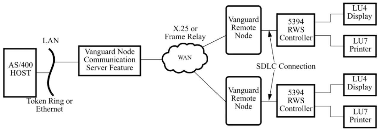
For networks with a limited number of RWS controllers, the conversion process can be done in one Vanguard product equipped with the AS/400 5494 Communications Server feature. Typically, this Vanguard product will be located close to the AS/400 host system.
The standard Vanguard SNA Applications Ware handles the interfaces between the remote controllers and the remote Vanguard nodes, using SDLC. The remote Vanguard nodes are linked to the Vanguard node (which contains the feature), via X.25 or Frame Relay. This Vanguard node is then connected to the AS/400 through a LAN connection (Ethernet or Token Ring). Figure 2-1 illustrates this network design.
Configuration Planning and Network Topologies
Figure 2-1. Single Vanguard Node with AS/400 5494 Communication Server Feature
Multiple Vanguard Nodes with Feature
For larger networks, the topology design can have multiple remote Vanguard nodes (with the feature), each of which handles a number of IBM or IBM-compatible Remote Work Station (RWS) controllers. These multiple Vanguards can be configured for Frame Relay connections to the AS/400. You can design a network with two stages of Vanguard products, to use Frame Relay (RFC1490) or X.25 WAN networks.
Note
For complex network designs, it is recommended that you consult with
Customer Service prior to implementation. Certain network designs may require additional bridging or conversion requirements beyond the scope of this manual.
Other Network Architectures
Other network architectures can be implemented using the Vanguard node with this feature, and other equipment. For example, you can connect multiple Vanguard conversion nodes to the AS/400 using Frame Relay (RFC1490). This design will require Frame Relay equipment for the AS/400. Another network design may utilize multiple LAN connections for both remote and local Vanguard stations.
AS/400 HOST LAN Token Ring or Ethernet LU4 Display LU7 Printer 5394 RWS Controller SDLC Connection Vanguard Remote Node WAN X.25 or Frame Relay Vanguard Node Communication Server Feature LU4 Display LU7 Printer 5394 RWS Controller Vanguard Remote Node
Configuration Examples
Configuration Examples
Introduction This section contains examples of configurations, with the accompanying
configuration parameters that you will have to set or modify. In some instances, there will be no change to the parameters from a standard Vanguard configuration.
Configuration Examples
The three configuration examples show simple diagrams of possible network applications for the AS/400 5494 Communications Server feature. The configurations shown are for:
• AS/400 Host system
• Vanguard node (with the AS/400 5494 Communications Server feature) • Vanguard nodes without the feature
• RWS Controllers and attached devices
Each example is designed to show different configuration factors and combinations. The Token Ring LAN, Ethernet LAN, and Frame Relay line definitions between the AS/400 and the Vanguard product (with the AS/400 5494 Communications Server feature) are presented as separate examples.
Configuration Examples
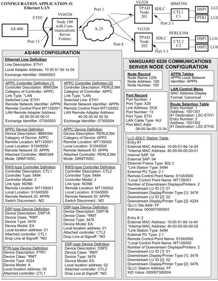
Configuration Example #1
Introduction The first configuration example shows the AS/400 5494 Communications Server feature utilized in an Ethernet LAN configuration. Figure 2-2 and Figure 2-3 show the network diagram and the key configuration parameters.
Note
Figure 2-2 and Figure 2-3 should be read together. The parameters are shown below the figure, going from the AS/400 on the left side to the controllers and devices on the right side.
Description The Communications Server feature is installed in a Vanguard 6520 node, designated as Node 100. The Vanguard product is attached to the AS/400 Host system through an Ethernet LAN in the upstream direction, and to other Vanguard products
downstream through X.25 connections.
The downstream Vanguards (Node 201 and Node 202) are linked via SDLC to controllers C1/CTL1 and C2/CTL2, which in turn have attached devices.
Note
The Host AS/400 Network Attribute Definition contains the required Host Control Point Name. This name is necessary for Vanguard configuration. The AS/400 System Administrator can supply this information.
Configuration Examples
Figure 2-2. Ethernet LAN Example (Page 1) APPC Controller Definition [1]
Controller Description: IBM5394 Category of Controller: APPC Link Type: *LAN
Switched Line: ETH1
Remote Network Identifier: APPN Remote Control Point MT13S001 LAN Remote Adapter Address:
40 00 00 00 00 01 Exchange Identifier: 07300003 APPC Device Definition Device Description: IBM5394 Category of Device: APPC Remote Location: MT13S001 Local Location: S10A5500 Remote Network ID: APPN Attached Controller: IBM5394 Mode: QRMTWSC
APPC Device Definition Device Description: PERLE394 Category of Device: APPC Remote Location: MT13S002 Local Location: S10A5500 Remote Network ID: APPN Attached Controller: PERLE394 Mode: QRMTWSC
APPC Controller Definition [2] Controller Description: PERLE394 Category of Controller: APPC Link Type: *LAN
Switched Line: ETH1
Remote Network Identifier: APPN Remote Control Point MT13S002 LAN Remote Adapter Address:
40 00 00 00 00 02 Exchange Identifier: 07300004
RWS-type Controller Definition Controller Description: CTL1 Controller Type: 5494 Controller Model: 2 Link type: NONE
Remote Location: MT13S001 Local Location: S10A5500 Remote Network ID: APPN Switch Disconnect.: NO
RWS-type Controller Definition Controller Description: CTL2 Controller Type: 5494 Controller Model: 2 Link type: NONE
Remote Location: MT13S002 Local Location: S10A5500 Remote Network ID: APPN Switch Disconnect.: NO DSP-type Device Definition
Device Description: DSP1A Device Class: *RMT Device Type: 3476 Device Model: EA Local location address: 01 Attached controller: CTL1 Drop Line at Signoff: *NO
DSP-type Device Definition Device Description: DSP1B Device Class: *RMT Device Type: 3476 Device Model: EA Local location address: 01 Attached controller: CTL2 Drop Line at Signoff: *NO
PTR-type Device Definition Device Description: PTR1 Device Class: *RMT Device Type: 4224 Device Model: A
Local location address: 02 Attached controller: CTL1 IBM5394 SDLC Port 2-1 Port 13 Port 1 TPAD Node 201 Node 100 with Com-munications Server Feature CONFIGURATION APPLICATION #1 Ethernet LAN X.25 VG6520 PERLE394 SDLC Port 3-1 TPAD Node 202 DSP1 DSP2 Port 8 VG320 VG320 AS/400 CONFIGURATION LLC-SDLC Station Table Entry #1
External MAC Address: 10-00-51-9d-1e-04 *Internal MAC Address: 40-00-00-00-00-01 Internal SAP: 04
External SAP: 04
Ethernet Frame Type: 802.3 *Link Station Type: 5494 External PU Type: 2.1
Remote Control Point Name: S10A5500 *Local Control Point Name: MT13S001 Number of Downstream Displays/Printers: 2 Downstream LU ID [1]: 01
Downstream Display/Printer Type [1]: 3476 Downstream LU ID [2]: 02
Downstream Display/Printer Type [2]: 4224 QLLC Sta.Addr: FF
XidValue: 000007300003 Entry #: 2
External MAC Address: 10:00-51-9d-1e-04 *Internal MAC Address: 40-00-00-00-00-02 *Link Station Type: 5494
External PU Type: 2.1
Remote Control Point Name: S10A5500 *Local Control Point Name: MT13S002 Number of Downstream Displays/Printers: 2 Downstream LU ID [1]: 01
Downstream Display/Printer Type [1]: 3476 Downstream LU ID [2]: 02
Downstream Display/Printer Type [2]: 3476 QLLC Station Address: FF
XID Value: 000007300004
VANGUARD 6520 COMMUNICATIONS SERVER NODE CONFIGURATION
Node Record
Node Name: LEN Node Address: 100 Node Number: 100
Port Record
Port Number: 1 Port Type: X25 Link Address: DCE Port Number: 13 Port Type: ETH LAN Cable Type: AUI Port MAC Addr:
08-00-3e-00-12-34
LAN Control Menu
MAC Address Display Format: Canonical
APPN Tables
APPN Local Network Identifier: APPN
Ethernet Line Definition
Line Description: ETH1
Local Adapter Address: 10 00 51 9d 1e 04 Exchange Identifier: 05600003
Route Selection Table
Entry Number: 1 Address: 1001301 #1 Destination: LSC-ETH1 Entry Number: 2 Address: 1001302 #1 Destination: LSC-ETH2 DSP1 PTR1 CTL1 C1 CTL2 C2 LU01 LU02 LU01 LU02 ETH1 AS 400
DSP-type Device Definition Device Description: DSP2 Device Class: *RMT Device Type: 3476 Device Model: EA Local location address: 02 Attached controller: CTL2 Drop Line at Signoff: *NO
Configuration Examples
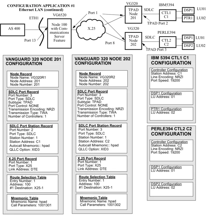
Figure 2-3. Ethernet LAN Example (Page 2)
VANGUARD 320 NODE 201 CONFIGURATION
CONFIGURATION APPLICATION #1 Ethernet LAN (continued)
Node Record Node Name: VG320R2 Node Address: 202 Node Number: 202 VANGUARD 320 NODE 202 CONFIGURATION
SDLC Port Station Record
Port Number: 3 Port Type: SDLC Station Number: 1 Station Address: C2 Autocall Mnemonic:: hpad QLLC Option: XID3
IBM5394 SDLC
Port 13
Port 1 TPADNode 201 Node 100 with Com-munications Server Feature X.25 VG6520 PERLE394 SDLC TPAD Node 202 DSP1 DSP2 Port 8 VG320 VG320 DSP1 PTR1 CTL1 C1 CTL2 C2 LU01 LU02 LU01 LU02 ETH1 AS 400 TPAD Port 3 TPAD Port 2 Node Record Node Name: VG320R1 Node Address: 201 Node Number: 201 SDLC Port Record Port Number: 3 Port Type: SDLC Subtype: TPAD Port Control: NONE
Transmission Encoding: NRZI Transmission Type: TWA Number of Controllers: 1
SDLC Port Station Record
Port Number: 2 Port Type: SDLC Station Number: 1 Station Address: C1 Autocall Mnemonic:: hpad QLLC Option: XID3
X.25 Port Record
Port Number: 1 Port Type: X25 Link Address: DTE
Route Selection Table
Entry Number: 1 Address: 100 #1 Destination: X25-1
Mnemonic Table
Mnemonic Name: hpad Call Parameters: 1001301
SDLC Port Record
Port Number: 3 Port Type: SDLC Subtype: TPAD Port Control: NONE
Transmission Encoding: NRZI Transmission Type: TWA Number of Controllers: 1
X.25 Port Record
Port Number: 1 Port Type: X25 Link Address: DTE
Route Selection Table
Entry Number: 1 Address: 100 #1 Destination: X25-1
Mnemonic Table
Mnemonic Name: hpad Call Parameters: 1001302 IBM 5394 CTL1 C1 CONFIGURATION PERLE394 CTL2 C2 CONFIGURATION Controller Configuration Station Address: C1 Line Encoding: NRZI Port Speed: 19200 DSP1 Configuration LU Address: 01 PTR1 Configuration LU Address: 02 Controller Configuration Station Address: C2 Line Encoding: NRZI Port Speed: 19200
DSP1 Configuration LU Address: 01
DSP2 Configuration LU Address: 02
Configuration Examples
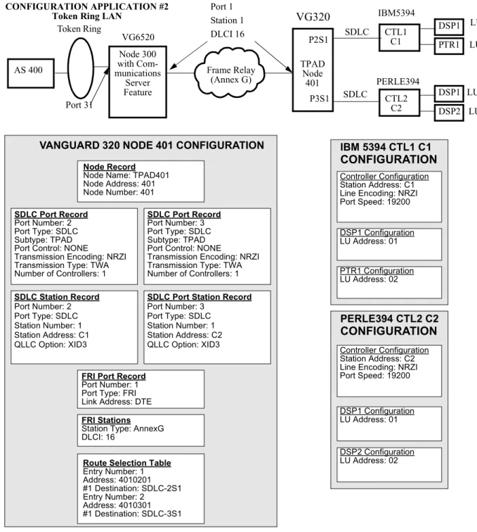
Configuration Example #2
Introduction The second configuration example shows the AS/400 5494 Communications Server feature utilized in a Token Ring LAN configuration. Figure 2-4 and Figure 2-5 show the network diagram and the key configuration parameters.
Note
Figure 2-4 and Figure 2-5 should be read together. The parameters are shown below the figure, going from the AS/400 on the left side to the controllers and devices on the right side.
Description This example shows the AS/400 5494 Communications Server software installed in a Vanguard 6520 Node, designated as Node 300. The Vanguard product is attached to the AS/400 Host system through a Token Ring LAN in the upstream direction, and to a Vanguard product downstream through Frame Relay (Annex G) connections. The downstream Vanguard (Node 401) is linked via SDLC to the controllers (CTL1 and CTL2), which in turn have attached devices (for CTL1 these devices are DSP1 and PTR1, and for CTL2 the attached devices are DSP1, DSP2, and DSP3).
You should notice that the Token Ring LAN requires a different AS/400
configuration, as well a different configuration for the Vanguard product with the Communications Server feature, compared to the first configuration application example. In addition, the Frame Relay WAN requires that both Vanguard nodes (Node 300 and Node 401) be configured with Frame Relay ports and stations. You should also notice that the three display devices attached to CTL 2 will each require a definition in the AS/400 configuration.
Configuration Examples
VANGUARD 6520 COMMUNICATIONS SERVER NODE CONFIGURATION
Token Ring Line Definition
Line Description: TRLINE1
Local Adapter Address: 10 00 51 9d 1e 04 Exchange Identifier: 05600003
APPC Controller Definition [1] Controller Description: IBM5394 Category of Controller: APPC Link Type: *LAN
Switched Line: TRLINE1 Remote Network ID: APPN Remote Control Point MT31S001 LAN Remote Adapter Address:
40 00 00 00 00 01 Exchange Identifier: 07300007
APPC Device Definition Device Description: IBM5394 Category of Device: APPC Remote Location: MT31S001 Local Location: S10A5500 Remote Network ID: APPN Attached Controller: IBM5394 Mode: QRMTWSC
APPC Device Definition Device Description: PERLE394 Category of Device: APPC Remote Location: MT31S002 Local Location: S10A5500 Remote Network ID: APPN Attached Controller: PERLE394 Mode: QRMTWSC
APPC Controller Definition [2] Controller Description: PERLE394 Category of Controller: APPC Link Type: *LAN
Switched Line: TRLINE1 Remote Network ID: APPN Remote Control Point MT31S002 LAN Remote Adapter Address:
40 00 00 00 00 02 Exchange Identifier: 07300009
RWS-type Controller Definition Controller Description: CTL1 Controller Type: 5494 Controller Model: 2 Link type: NONE
Remote Location: MT31S001 Local Location: S10A5500 Remote Network ID: APPN Switch Disconnect.: NO
RWS-type Controller Definition Controller Description: CTL2 Controller Type: 5494 Controller Model: 2 Link type: NONE
Remote Location: MT31S002 Local Location: S10A5500 Remote Network ID: APPN Switch Disconnect.: NO
DSP-type Device Definition Device Description: DSP1A Device Class: *RMT Device Type: 3476 Device Model: EA Local location address: 01 Attached controller: CTL1 Drop line at signoff: *NO
DSP-type Device Definition Device Description: DSP1B Device Class: *RMT Device Type: 3476 Device Model: EA Local location address: 01 Attached controller: CTL2 Drop line at signoff: *NO
PTR-type Device Definition Device Description: PTR1
DSP-type Device Definition Device Description: DSP2 Device Class: *RMT. . . .
Node Record
Node Name: Node300 Node Address: 300 Node Number: 300 Port Record Port Number: 1 Port Type: FR Port Number: 31 Port Type: TR Port MAC Addr:
10:00:7C:00:12:34
LAN Control Menu
MAC Address Display For-mat: Non-Canonical
APPN Tables
APPN Local Network Identifier: APPN
Route Selection Table
Entry Number: 1 Address: 401*
#1 Destination: FRI-1S1
FRI Stations
Port Number: 1 Station: 1 DLCI: 16
LLC-SDLC Station Table Entry #1
External MAC Address: 10:00:51:9d:1e:04 *Internal MAC Address: 40:00:00:00:00:01 *Link Station Type: 5494
External PU Type: 2.1
Remote Control Point Name: S10A5500 *Local Control Point Name: MT31S001 Number of Downstream Displays/Printers: 2 Downstream LU ID [1]: 01
Downstream Display/Printer Type [1]: 3476 Downstream LU ID [2]: 02
Downstream Display/Printer Type [2]: 4224 QLLC Sta.Addr: FF
XidValue: 000007300007 Autocall Mnemonic: 4010201 Entry #: 2
External MAC Address: 10:00:51:9d:1e:04 *Internal MAC Address: 40:00:00:00:00:02 *Link Station Type: 5494
External PU Type: 2.1
Remote Control Point Name: S10A5500 *Local Control Point Name: MT31S002
Mnemonic Table Entry Number: 1 Mnemonic Name: 4010201 Call Parameters: 4010201 Entry Number: 2 Mnemonic Name: 4010301 Call Parameters: 4010301 Token Ring CONFIGURATION APPLICATION #2
Token Ring LAN IBM5394
SDLC Port 31 FRI Port 1 Station 1 DLCI=16 Frame Relay (Annex G) VG6520 PERLE394 SDLC DSP1 DSP2 DSP1 PTR1 CTL1 C1 CTL2 C2 LU01 LU02 LU01 LU02 AS 400 TPADNode 401 P2S1 P3S1 Node 300 with Com-munications Server Feature
AS/400 CONFIGURATION
VG320Configuration Examples
Figure 2-5. Token Ring LAN Example (Page 2)
VANGUARD 320 NODE 401 CONFIGURATION IBM 5394 CTL1 C1
CONFIGURATION
PERLE394 CTL2 C2
CONFIGURATION
Token Ring
CONFIGURATION APPLICATION #2
Token Ring LAN IBM5394
SDLC Port 31 Frame Relay (Annex G) VG6520 PERLE394 SDLC DSP1 DSP2 DSP1 PTR1 CTL1 C1 CTL2 C2 LU01 LU02 LU01 LU02 AS 400 TPADNode 401 P2S1 P3S1 SDLC Station Record Port Number: 2 Port Type: SDLC Station Number: 1 Station Address: C1 QLLC Option: XID3
FRI Port Record
Port Number: 1 Port Type: FRI Link Address: DTE
SDLC Port Record
Port Number: 2 Port Type: SDLC Subtype: TPAD Port Control: NONE
Transmission Encoding: NRZI Transmission Type: TWA Number of Controllers: 1
Node Record
Node Name: TPAD401 Node Address: 401 Node Number: 401 SDLC Port Record Port Number: 3 Port Type: SDLC Subtype: TPAD Port Control: NONE
Transmission Encoding: NRZI Transmission Type: TWA Number of Controllers: 1
SDLC Port Station Record
Port Number: 3 Port Type: SDLC Station Number: 1 Station Address: C2 QLLC Option: XID3
Route Selection Table
Entry Number: 1 Address: 4010201 #1 Destination: SDLC-2S1 Entry Number: 2 Address: 4010301 #1 Destination: SDLC-3S1 FRI Stations
Station Type: AnnexG DLCI: 16
Controller Configuration Station Address: C1 Line Encoding: NRZI Port Speed: 19200 DSP1 Configuration LU Address: 01 PTR1 Configuration LU Address: 02 Controller Configuration Station Address: C2 Line Encoding: NRZI Port Speed: 19200 DSP1 Configuration LU Address: 01 DSP2 Configuration LU Address: 02 Node 300 with Com-munications Server Feature Port 1 Station 1 DLCI 16 VG320
Configuration Examples
Configuration Example #3
Introduction The third configuration example shows the AS/400 5494 Communications Server feature utilized in a Frame Relay configuration. Figure 2-6 and Figure 2-7 show the network diagram and the key configuration parameters.
Note
Figure 2-6 and Figure 2-7 should be read together. The parameters are shown below the figure, going from the AS/400 on the left side to the controllers and devices on the right side.
Description This example shows the AS/400 5494 Communications Server software installed in a Vanguard 6520 Node, designated as Node 900. The Vanguard product is attached to the AS/400 Host system through a RFC1490 Frame Relay WAN in the upstream direction, and to the controllers (C1/CTL1 and C2/CTL2) in the downstream direction. The Frame Relay WAN requires that the Vanguard node be configured with Frame Relay ports and stations.
The controllers have multiple attached devices: for CTL1, these devices are DSP1 and PTR1; and for CTL2, the attached devices are DSP1, DSP2, and DSP3. Each controller and its attached devices must be defined in the AS/400.
The AS/400 5494 Communications Server Feature in this example allows the connection of remote controllers to the AS/400 through a Frame Relay network, rather than direct lines or modem connections.
Configuration Examples
Figure 2-6. Frame Relay Example (Page 1) CONFIGURATION
APPLICATION #3 RFC1490 Frame Relay
VANGUARD 6520 COMMUNICATIONS SERVER NODE CONFIGURATION
Node Record
Node Name: Node900 Node Address: 900 Node Number: 900
Port Record
Port Number: 1 Port Type: FRI
APPN Tables
APPN Local Network Identifier: APPN
Route Selection Table
Entry Number: 1 Address: 9000101 #1 Destination: LSC-FR1 Entry Number: 2 Address: 9000102 #1 Destination: LSC-FR2 FRI Station Port Number: 1 Station: 1 DLCI: 16 Mnemonic Table Entry Number: 1 Mnemonic Name: hpad1 Call Parameters: 9000101 Entry Number: 2
Mnemonic Name: hpad2 Call Parameters: 9000102
SDLC Port Station Record
Port Number: 2 Port Type: SDLC Station Number: 1 Station Address: C1 Autocall Mnemonic: hpad1 QLLC Option: XID3 Port Number: 3 Port Type: SDLC Station Number: 1 Autocall Mnemonic: hpad QLLC Option: XID3
SDLC Port Record
Port Number: 2 Port Type: SDLC Subtype: TPAD Port Control: NONE
Transmission Encoding: NRZI Transmission Type: TWA Number of Controllers: 1 Port Number: 3 Port Type: SDLC Subtype: TPAD Port Control: NONE
Transmission Encoding: NRZI Transmission Type: TWA Number of Controllers: 1 Communication Server Node Settings Continued On Next Page IBM5394 SDLC CTL1 C1 FRI Port 1 Station 1 Node 900 Frame Relay RFC1490 VG6520 PERLE394 CTL2 C2 DSP1 DSP2 S10A5500 P3S1 P2S1 DSP3 SDLC AS/400 DLCI = 16 DSP1 PTR1 LU01 LU02 LU01 LU02 LU03
Frame Relay Line Definition
Line Description: FRLINE Attached NWI: FRNWI DLC Identifier: 16
Exchange Identifier: 056A5500
APPC Controller Definition [1]
Controller Description: IBM5394 Category of Controller: APPC Link Type: *FR
Remote Network ID: APPN Remote Control Point MT31S001 Switched Disconnect: *NO Exchange Identifier: 07300007
APPC Device Definition
Device Description: IBM5394 Category of Device: APPC Remote Location: MT31S001 Local Location: S10A5500 Remote Network ID: APPN Attached Controller: IBM5394 Mode: QRMTWSC
APPC Device Definition
Device Description: PERLE394 Category of Device: APPC Remote Location: MT31S002 Local Location: S10A5500 Remote Network ID: APPN Attached Controller: PERLE394 Mode: QRMTWSC
APPC Controller Definition [2]
Controller Description: PERLE394 Category of Controller: APPC Link Type: *FR
Remote Network ID: APPN Remote Control Point MT31S002 Switched Disconnect: *NO Exchange Identifier: 07300009
RWS-type Controller Definition
Controller Description: C1 Controller Type: 5494 Controller Model: 2 Link type: NONE
Remote Location: MT31S001 Switch Disconnect.: NO
RWS-type Controller Definition
Controller Description: C2 Controller Type: 5494 Controller Model: 2 Link type: NONE
Remote Location: MT31S002 Switch Disconnect.: NO
DSP-type Device Definition
Device Description: DSP1A Device Class: *RMT Device Type: 3476 Device Model: EA Local location address: 01 Attached controller: C1 Drop line at signoff: *NO
DSP-type Device Definition
Device Description: DSP1B Device Class: *RMT Device Type: 3476 Device Model: EA Local location address: 01 Attached controller: C2 Drop line at signoff: *NO
DSP-type Device Definition
Device Description: DSP2 Device Class: *RMT . . . .
DSP-type Device Definition
Device Description: DSP3 Device Class: *RMT Device Type: 3476 Device Model: EA Local location address: 03 Drop line at signoff: *NO Attached controller: C2
PTR-type Device Definition
Device Description: PTR1 Device Class: *RMT Device Type: 4224 Device Model: A
Local location address: 02 Attached controller: C1 Drop line at signoff: *NO
Configuration Examples
LLC-SDLC Station Table
Entry #2
*Frame Relay Port Number: 1 *Frame Relay Station Number: 1 1490 Encapsulation: LLC Internal SAP: 04 External SAP: 04 *Link Station Type: 5494 External PU Type: 2.1 Initiate TEST Frame: ON
Remote Control Point Name: S10A5500 *Local Control Point Name: MF00S002 Number of Downstream Displays/Printers: 3 Downstream LU ID [1]: 01
Downstream Display/Printer Type [1]: 3476 Downstream LU ID [2]: 02
Downstream Display/Printer Type [2]: 3476 Downstream LU ID [3]: 03
Downstream Display/Printer Type [3]: 3476 LLC Profile Name: DEFAULT
QLLC Station Address: 02 QLLC Options: NONE XID Value: 000007300009 IBM5394 SDLC CTL1 C1 FRI Port 1 Station 1 Node 900 Frame Relay RFC1490 VG6520 PERLE394 CTL2 C2 DSP1 DSP2 S10A5500 P3S1 P2S1 DSP3 SDLC AS/400 CONFIGURATION APPLICATION #3 RFC1490 Frame Relay (continued) DLCI = 16 DSP1 PTR1 LU01 LU02 LU01 LU02 LU03
VANGUARD 6520 COMMUNICATIONS SERVER NODE CONFIGURATION (continued)
LLC-SDLC Station Table
Entry #1
*Frame Relay Port Number: 1 *Frame Relay Station Number: 1 1490 Encapsulation: LLC Internal SAP: 04 External SAP: 04 *Link Station Type: 5494 External PU Type: 2.1 Initiate TEST Frame: ON
Remote Control Point Name: S10A5500 *Local Control Point Name: MF00S001 Number of Downstream Displays/Printers: 2 Downstream LU ID [1]: 01
Downstream Display/Printer Type [1]: 3476 Downstream LU ID [2]: 02
Downstream Display/Printer Type [2]: 4224 LLC Profile Name: DEFAULT
QLLC Station Address: 01 QLLC Options: NONE XID Value: 000007300007 IBM 5394 CTL1 C1 CONFIGURATION Controller Configuration Station Address: C1 Line Encoding: NRZI Port Speed: 19200 DSP1 Configuration LU Address: 01 PERLE394 CTL2 C2 CONFIGURATION Controller Configuration Station Address: C2 Line Encoding: NRZI Port Speed: 19200 DSP1 Configuration LU Address: 01 DSP3 Configuration LU Address: 03 DSP2 Configuration LU Address: 02
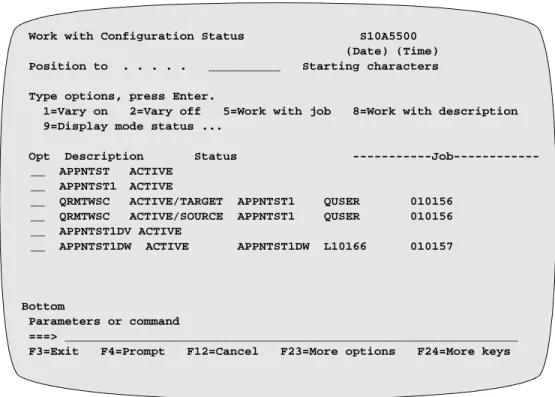
Configuring the AS/400 Host System
Configuring the AS/400 Host System
Introduction This section contains configuration information for the AS/400 and describes the configuration status display.
Configuring the AS/400 Host System
AS/400 Host System Configuration Requirements
GeneralConfiguration Requirements
The AS/400 Host system must be configured correctly to support this feature in the Vanguard. You must set the AS/400 definition fields to match or complement the other network configuration parameters. The key elements in the AS/400 which must be matched are:
• Line Definition − one per LAN and/or Frame Relay connection • APPC Controller Definition − one per downstream controller • APPC Device Definition − one per downstream controller
• Mode Definition − QRMTWSC is supplied by IBM. It is specified in the APPC Device Definition
• RWS (Remote Work Station Controller) Definition − one per attached downstream controller (workstation)
• Display Device Definition − one per attached display device • Printer Device Definition − one per attached printer device
Refer to your Host system and controller documentation for specific system information.
Note
The configuration values you use in the Host system must match your network logical and physical configuration. In particular, description names and identifiers must be identical.
Accessing AS/400 Definition Menus
You can access the AS/400 definition menus and screens through two different methods:
• Command Line Interface (using the specific menu or screen name) • Menu selections
Command Line Interface
The AS/400 allows you to enter commands and access screens through the command line interface. Refer to your AS/400 documentation for details of how this interface operates, and for command definitions and examples.
AS/400 Main Menu
The AS/400 Host System definition (configuration) menus and screens can be accessed through the AS/400 Main menu. The Communications option has sub-menus for the key definitions you will need to access.
AS/400 Line Definition Options
The AS/400 Line Definition menu defines the parameters for the interface lines from the Host system to the controllers. There are three types of line definitions which can
Configuring the AS/400 Host System
AS/400 Token Ring LAN Line Definition
The key AS/400 Token Ring LAN Line Definition parameters you will need to configure for the Vanguard Communications Server feature are listed here. You must provide the remaining definition parameters as necessary to configure the AS/400. These other parameters should use the default or standard setting for your
equipment.
The key parameters for the AS/400 Communications Server feature are: • Line description
• Line speed
• Maximum frame size • Local adapter address • Exchange identifier • Autocreate controller
AS/400 Token Ring LAN Definition Key Parameters
These key parameters you will have to set or check for the AS/400 5494 Communication Server feature are described here.
Line Description
Range: [Name]
Suggested Values:
Use a name to identify the Token Ring LAN that is attached to the Vanguard.
Example: TRLINE
Description: Identifies the name applied to the LAN connection to the Vanguard (and the attached controllers).
This is the type of line used by the AS/400 to connect with the network to reach the attached controllers.
Line speed
Range: 4M, 16M
Suggested Value:
4M or 16M
Matches the Ring Speed parameter for the Vanguard Token Ring Port.
Description: Defines the nominal Token Ring LAN data rate. The Vanguard Communications Server feature will only support a line speed of 4 or 16 Mbps.
Configuring the AS/400 Host System
Maximum frame size
Range: N/A
Suggested Value:
1500 (recommended)
Description: Defines the packet size used to transfer data through the network. If you select a smaller frame size, the throughput of the network will decrease. Larger frame sizes may not be processed properly through the Vanguard.
Local adapter address
Range: Valid six hex-byte MAC address Suggested
Value:
Set the External MAC Address parameter in the Vanguard LLC-SDLC Station Table to match the AS/400 local adapter address.
Description: Shows the MAC address for the AS/400 local adapter connecting to the Token Ring LAN.
Exchange identifier
Range: Valid XID Format 3 identifier Suggested
Value:
Use the XID that uniquely identifies the AS/400.
Description: Shows the AS/400 XID 3 value exchanged with the Vanguard during the initial start-up sequence.
Autocreate controller
Range: *YES, *NO
Suggested Value:
*NO
AS/400 Match Value:
RWS Controller Definition parameter for Autocreate device is set to *NO.
Configuring the AS/400 Host System
AS/400 Ethernet LAN Line Definition
The key AS/400 Ethernet LAN Line Definition parameters you will need to
configure for the Vanguard Communications Server feature are listed here. You must also configure the remaining AS/400 line definition parameters as required.These other parameters should use the default or standard setting for your equipment. The key parameters you will have to set or check for the AS/400 5494
Communications Server feature are described in the following tables:
Line Description
Range: [Name]
Suggested Value:
Use a name to identify the LAN that attaches to the Vanguard. Example: ETHLINE
Description: Identifies the name for the line that the Vanguard uses to attach to the Ethernet LAN.
Local adapter address
Range: Valid six hex-byte MAC address Suggested
Value:
Set the External MAC Address parameter in the Vanguard LLC-SDLC Station Table to match the AS/400 local adapter address.
Description: Shows the MAC address for the AS/400 local adapter connecting to the Ethernet LAN.
Exchange identifier
Range: Valid XID Format 3 identifier. Suggested
Value:
Use the XID that uniquely identifies the AS/400.
Description: Identifies the AS/400 XID 3 value exchanged with the Vanguard during the initial start-up sequence.
Link speed
Range: 10M, 100M
Suggested Value:
10M
This matches the parameter in the Vanguard Ethernet Port Record. Description: Defines the Ethernet LAN speed. 10M is the standard Ethernet
Configuring the AS/400 Host System
AS/400 Frame Relay (RFC1490) Line Definition Parameters
The key AS/400 RFC1490 Frame Relay Line Definition parameters you will need to configure for the Vanguard Communications Server feature are listed below. You must also configure the remaining AS/400 line definition parameters as required. The key parameters you will have to set or check for the AS/400 5494
Communications Server feature are described in the following tables:
Line Description
Range: [Name]
Suggested Value:
Use a name to identify the Frame Relay line that attaches to the Vanguard.
Example: FRLINE
Description: Identifies the line used by the Vanguard to attach to the AS/400 via Frame Relay.
Attached nonswitched NWI
Range: [Name]
Suggested Value:
Select a name for the nonswitched network interface. Example: FRNWI
Description: Identifies the NWI (Non-switched Network Interface) to which this line is attached.
DLC identifier
Range: Valid DLCI identifier. Suggested
Value:
Set the DLC identifier (“DLCI”) to match the DLCI identifier in the Vanguard FRI Station DLCI parameter, or to match the DLCI provided by the Frame Relay network provider.
Description: Establishes connections through the Frame Relay network.
Maximum frame size
Range: N/A
Configuring the AS/400 Host System
AS/400 APPC Controller Definition and Parameters
The AS/400 APPC (Advanced Peer-to-Peer Communication) Controller Definition has attached remote controller information. The key parameters you will need to configure for the Vanguard Communications Server feature are listed in the following tables. You must also provide remaining definition parameters to configure the AS/400.
The key parameters you will have to set or check for the AS/400 5494 Communication feature are described here.
Exchange identifier
Range: Valid XID Format 3 identifier Vanguard
Match Value:
Use the XID that uniquely identifies the AS/400.
Description: Identifies the AS/400 XID 3 value exchanged with the Vanguard during the initial start-up sequence.
Controller description
Range: [Name]
Suggested Value:
Use a name to identify the Vanguard and LLC-SDLC station to attach to this controller.
Description: Identifies the attached controller.
Category of controller
Range: *APPC
Suggested Value:
*APPC.
Description: Defines the controller as an APPC (Advanced Peer-to-Peer Communication) device.
Maximum frame size
Range: 265 to 16393, 265, 265, 512 . . . Suggested
Value:
16393
Description: Shows the maximum frame size allowed by the AS/400 in the network.