A High-Level Virtual Platform for Early MPSoC
Software Development
Jianjiang Ceng, Weihua Sheng, Jeronimo Castrillon, Anastasia Stulova,
Rainer Leupers, Gerd Ascheid and Heinrich Meyr
Institute for Integrated Signal Processing Systems RWTH Aachen University, Germany
{ceng, sheng, castrill, stulova, leupers}@iss.rwth-aachen.de
ABSTRACT
Multiprocessor System-on-Chips (MPSoCs) are nowadays widely used, but the problem of their software development persists to be one of the biggest challenges for develop-ers. Virtual Platforms (VPs) are introduced to the industry, which allow MPSoC software development without a hard-ware prototype. Nevertheless, for developers in early design stage where no VP is available, the software programming support is not satisfactory.
This paper introduces a High-level Virtual Platform (HVP) which aims at early MPSoC software development. The framework provides a set of tools for abstract MPSoC simu-lation and the corresponding application programming sup-port in order to enable the development of reusable C code at a high level. The case study performed on several MP-SoCs shows that the code developed on the HVP can be easily reused on different target platforms. Moreover, the high simulation speed achieved by the HVP also improves the design efficiency of software developers.
Categories and Subject Descriptors
I.6.5 [Simulation and Modeling]:Model Development - Modeling Methodologies
General Terms
Design
Keywords
Embedded, MPSoC, Software, Parallel Programming, Simulation, Virtual Platform, System Level Design
1.
INTRODUCTION
Multiprocessor System-on-Chips (MPSoCs) are nowadays used in a wide variety of products ranging from automo-biles to personal entertainment appliances due to their good
Permission to make digital or hard copies of all or part of this work for personal or classroom use is granted without fee provided that copies are not made or distributed for profit or commercial advantage and that copies bear this notice and the full citation on the first page. To copy otherwise, to republish, to post on servers or to redistribute to lists, requires prior specific permission and/or a fee.
CODES+ISSS’09,October 11–16, 2009, Grenoble, France. Copyright 2009 ACM 978-1-60558-628-1/09/10 ...$10.00.
balance between performance and energy efficiency. Nev-ertheless, although MPSoCs have been adopted as the de facto standard architecture for years, the problem of their software development still stubbornly persists to be one of the biggest challenges for developers [18].
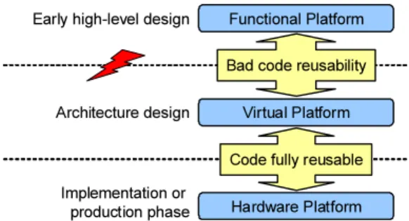
In the past few years, Virtual Platforms (VPs) have been introduced by companies like Virtio [26] to enable software development before a hardware prototype is available. To-gether with high-level functional platforms and real hard-ware platforms, today, developers can use three kinds of platforms to do software development. Nonetheless, the choice of which platform to use mostly depends on the de-sign stage the developer is in. Figure 1 gives an overview of them.
Functional Platform
Virtual Platform
Hardware Platform Early high-level design
Architecture design
Implementation or production phase
Code fully reusable Bad code reusability
Figure 1: MPSoC Development Platforms
Hardware platformsare the most traditional platforms for software development. However, their development is typically very time consuming. Normally, software develop-ers are able to get access to them only in the implementation or the production phase, which could be too late for starting software development.
Virtual platformsemploy instruction-set simulators and provide software developers a binary compatible environ-ment in which executable files for the target platform can be executed without modification. They are much easier to be built than hardware prototypes; hence they are more and more used today in order to let developers start software development early. Nevertheless, since their development requires the concrete specification of the target platform, which could be available only in the late architecture design phase, it is not possible for programmers to use them in early design stage.
Functional platformsdo high-level simulation without much architecture information. They are often used by
de-velopers in early design stage, when architecture details are not fully determined. Applications are typically executed natively in a workstation, whose environment is largely dif-ferent from a target MPSoC platform. Therefore, applica-tions which are developed at high-level, can hardly be di-rectly reused on target platforms. To close this gap, code synthesis tools are proposed, which are supposed to gener-ate target source code from high-level models automatically. However, in the embedded domain, the acceptance of such approach is until today not very high; most developers still use theold C language for programming [8].
Besides, the software stack of an MPSoC platform has several layers, which typically includes application, middle-ware and OS, as depicted in figure 2. The development of applications in the highest layer could heavily depend on the target specific low-level softwares which need to be first developed by firmware developers. As a result, it is difficult for application programmers to start writing target software right from the beginning of the project and keep the code reusable.
Application Middleware
Operating System E.g. Linux
E.g. TCP/IP Protocol Stack E.g. Web Browser
Figure 2: Typical MPSoC Software Stack
In this paper, we propose a High-level Virtual Platform (HVP) which aims at supporting MPSoC software devel-opment in early design stage when both VP and hardware prototype are not at hand. Developers are provided with:
• A generic high-level MPSoC simulator which does func-tional simulation and abstracts away the hardware de-tails and the OS of the target platform;
• A software toolchain for application programming and the corresponding code generation; and
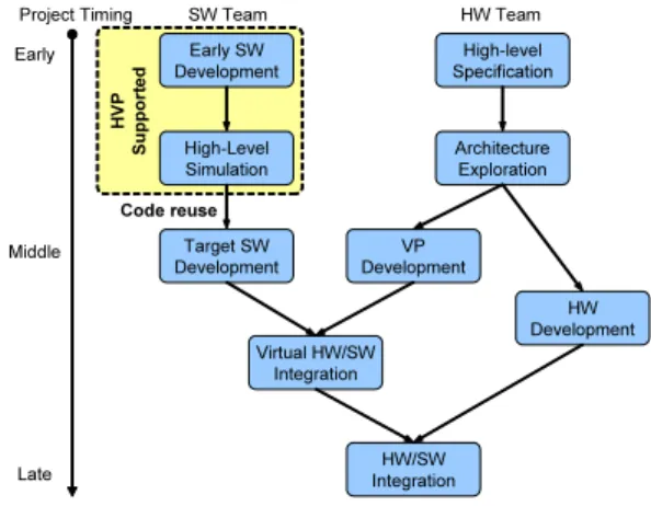
• The possibility of using instruction-set simulators with functional simulation together and testing the code in a target environment before a complete VP is available. Figure 3 illustrates the HW/SW co-development flow which involves the HVP. The contribution of the HVP is in the early stage; it allows the software team to start the devel-opment from the very beginning of the project without the need of a VP or a HW prototype. Parallel applications can be modeled in the HVP at the abstraction level of Com-municating Processes [5], which is architecture independent and reusable. The case study performed on several MPSoC platforms shows that the code developed on the HVP can be easily reused on different targets. In addition to that, the design efficiency is also improved by the high simulation speed achieved by the HVP.
The rest of this paper is organized as following: section 2 first discusses some works which are related to the HVP. An overview on the framework is then given in section 3. The HVP simulator, which is the simulation backbone, is intro-duced in section 4. After that, the issue of how to develop applications on top of the HVP is discussed with details in section 5. Section 6 shows the efficiency of the proposed approach through a case study performed on several MP-SoC platforms. Finally, we conclude the paper and give an outlook on the future work in section 7.
HVP Supported Early SW Development High-Level Simulation Target SW Development High-level Specification Architecture Exploration VP Development HW Development Virtual HW/SW Integration HW/SW Integration Code reuse SW Team HW Team Project Timing Early Middle Late
Figure 3: HVP Supported Design Flow
2.
RELATED WORK
In the past few years, System Level Design (SLD) has been introduced to handle the HW/SW design complexity of MP-SoCs. High-level simulation is often the first step in a SLD flow. For this purpose, different languages are used to model the application behavior. [11], [4] and [1] use SystemC to drive the design. Simulink and UML are also used for high-level modeling, e.g. in [22] and [2]. Some use C/C++, but the application must be modeled with specific APIs as Kahn Process Networks (KPNs) like in [25], [24] and [15]. The idea behind these high-level models is mainly software syn-thesis. Instead of using them directly in the target MPSoC, synthesis tools are typically provided to generate target C code from them. However, even with highly automated tool-chains, embedded programmers are still reluctant to adopt them because of different reasons, no new language or high-level programming model has been widely adopted in this area so far. For embedded software development, C is still the first choice today, which is the programming language supported by the HVP.
Abstract RTOS modeling works are also related to the HVP. In [17], a simulation framework is introduced, which uses an abstract RTOS model for task scheduling. How-ever, since behavior is not included in its application model, the framework is more suitable for the overall system design than the software development. Other frameworks model RTOS together with software behavior by using SystemC ([10], [12] and [23]) or SpecC ([7] and [10]) as their mod-eling language. Such approaches normally require the user to explicitly insert timing annotations into the source code, which reduces the code reusability. Works have been done in [13] and [19] to automate the annotation process. Their focuses are on the performance estimation; and hence the support for software development is limited. [6] and [9] use native execution to simulate both OS and user application. Since the software must be written based on the simulated OS, the solutions are not generic and difficult to be used for other platforms.
In [14], a work is introduced, which combines ISS and ab-stract RTOS model together. Unlike the HVP, which allows ISS and native simulation at the same time, the approach is for target software only and does not support native execu-tion.
in three aspects:
1. The HVP focuses solely on supporting software devel-opment at high-level. The programmer can write ap-plications directly in C and execute them in the HVP. 2. The HVP does not impose the use of any special pro-gramming model such as KPN. The programmer has the complete control on how the application shall be implemented.
3. The HVP itself does not contain any target specific component and is completely platform independent. The developed C code can be easily reused on different platforms.
3.
FRAMEWORK OVERVIEW
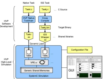
In early design stage, it is typical that a lot of details of the target platform are not determined. For example, the choice of processing elements could be unknown, because the system architect must first explore the design space; and the decision of low-level software usage, like the choice of OS, communication API etc., could be still in the hands of the firmware developer. In order to support application de-velopment in such a situation, the HVP provides a generic abstract MPSoC simulator so that applications can be simu-lated without much knowledge about the hardware and the software architecture of the target platform. An overview of the complete framework is given in figure 4. The structure of the HVP simulator is shown in the lower half of the figure.
SystemC Simulation Generic Shared Memories
Configuration File GUI Taski Taski .so Taskj VPE-m … … … Dynamic Load Shared libraries Taski.c HVP Native Toolchain Taskj.c ISS Wrapper .so Cross Compile Taskj.bin … C Source Target Binary HVP Software Development HVP High-Level Simulation
Native Task ISS Task
Figure 4: HVP Overview
As can be seen from the figure, the HVP simulator is built on top of SystemC [20]. In order to make the simulator generic, details of the target platform are abstracted away through the use of an abstract processor model called Vir-tual Processing Element (VPE) and the abstract OS model which is built into it. The communication between VPEs is realized through the generic shared memories which can be controlled and accessed in applications by using the HVP programming API. The applications provided by the user are completely decoupled from the simulator. They are com-piled into shared libraries and loaded dynamically before the simulation starts.
The configuration of the abstract MPSoC like the number of VPEs to be instantiated, the VPE parameters and the application-to-VPE mapping can be given in two ways, ei-ther through the HVP GUI manually or by loading an XML format configuration file. To setup an abstract MPSoC plat-form using the GUI, only mouse-clicks and drag-and-drop operations are required, which can be achieved within min-utes. During the simulation, settings like task mapping or VPE clock frequency, can be modified dynamically so that different application scenarios can be easily explored with-out restarting the simulation from the beginning. To use the simulator, a programmer is not required to have deep MP-SoC hardware knowledge or do any SystemC coding; there-fore he can focus on the application itself which software developers are more familiar with.
As mentioned earlier, applications are decoupled from the simulator. Here, the meaning of the decoupling is twofold. First, the applications are compiled into shared libraries which are physically independent. Second, each application is written as a standalone program in C, which has its own main function and does not interfere with the one of the Sys-temC kernel in the simulator. Due to this decoupling, the HVP is able to flexibly simulate the application behavior in two possible ways, namely native execution or instruction set simulation.
The upper half of figure 4 shows the development flows of both approaches. The former approach is supported through the use of an HVP specific software toolchain. The software is executed natively, and therefore the approach is fast, com-pletely processor independent and can be used at the very beginning of the MPSoC design. The later requires that the choice of processing element (PE) is known and an instruc-tion set simulator (ISS) must be available. This could be possible in a later design stage or the PE is reused from an earlier generation of platform or provided by a 3rd party IP vendor. From the HVP’s perspective, no restriction is imposed on how the software behavior should be simulated; and the developer can freely choose the approach which is more appropriate depending on his situation. Mixing the use of both is also allowed, which could be used when part of the platform is determined or developed.
In summary, the whole HVP framework is mainly com-posed of two parts:
• A generic abstract MPSoC simulatorwhich al-lows the programmer to easily create high-level models for MPSoCs and do functional simulation.
• A set of software toolswhich provide the program-mer with the possibility of simulating the application flexibly in different manners and keeping the source code reusable for both the functional platform and the target MPSoC.
In the following sections, the above mentioned parts as well as their usage will be discussed in detail.
4.
HVP SIMULATOR
The HVP simulator provides application developers a high-level abstraction of the underlying MPSoC platform. From a high-level perspective, an MPSoC can be seen as a set of processing elements, interconnections and peripherals. In the HVP simulator, the processing elements are abstracted
by using VPEs instead, the interconnections used for inter-processor communication are modeled using generic shared memories, and a virtual peripheral is provided for convenient output of graphical and text information.
The parallel operation of the components is simulated in the SystemC environment. The implementation of the HVP simulator is in line with the loosely-timed coding style and the temporal decoupling technique which are suggested by the TLM 2.0 standard for software application development [21]. Details of the major components of the HVP simulator will be elaborated in the rest of this section.
4.1
Virtual Processing Element
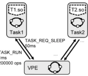
In the HVP simulator, a VPE is a high-level abstraction of a processing element and the operating system running on it. It is responsible for the control of the execution of the software tasks mapped to it. This includes the decisions of: which task should be executed (i.e. scheduling), how long the selected task should run (i.e. time slicing), and how many operations the task should perform in the given time slot (i.e. execution speed). Conversely, tasks can also request the VPE for OS services like sleep microseconds etc. The interaction between a VPE and tasks can be roughly illustrated as in figure 5, where the VPE sends out an event
TASK_RUNto let Task1execute 200,000 operations for 1ms,
and the task requests to sleep for 50ms during its execution.
VPE Task1 T1.so Task1 T1.so Task2 T2.so Task2 T2.so TASK_RUN 1ms 200000 ops TASK_REQ_SLEEP 50ms … …
Figure 5: VPE-Task Interaction Example
Technically, tasks and VPEs are implemented as SystemC modules. Their interaction is realized by the events which are communicated through the TLM channels between them. The following paragraphs will introduce the semantics of the VPE model and the task model.
4.1.1
VPE Model
A VPE can be described here as an event-driven finite state automaton which is a 7-tupleV = (S, s0, U, O, I, ω, ν)
with:
• S ={RESET, RU N, SW IT CH, IDLE}is the set of
explicit states;
• s0=RESET is the initial state of the VPE;
• U is the set of internal variables which represent the implicit states likeT IM E SLICE LEN GT H, etc; • O is the set of output events for task control, e.g.
T ASK RU N;
• I is the set of input events which could be sent by tasks, e.g. T ASK REQ SLEEP;
• ω:S×I→Ois the set of output functions in which functionalities like scheduling are implemented; and
• ν:S×I→S is the set of next-state functions, which manage the OS state.
From a user’s perspective, a VPE simply appears as a pa-rameterized abstract processor. The settings which can be configured by the user are mainly clock frequency, sched-uler and task mapping. Presently, three scheduling algo-rithms are implemented in the VPE, which are round-robin, earliest deadline first and priority based scheduling. These parameters can be adjusted both before and during the sim-ulation. This allows the programmer to change the platform and check the application behavior in different scenario con-veniently. Besides, the event history can be saved by the simulator in form of Value Change Dump (VCD) files, which can be used to check the VPE activity after the simulation for debugging purposes.
4.1.2
Task Model
A task in the HVP simulator can be seen as an event-driven nondeterministic finite state automaton, which is a 6-tupleT = (S, s0, I, O, ω, ν) consisting of:
• S ={READY, RU N, SU SP EN D}is the set of task
states;
• s0=READY is the initial state;
• I is the input events, e.g. T ASK RU N, which are sent by the VPE;
• Ois the output events, e.g. T ASK REQ SLEEP; • ω:S×I →P(O) is the output functions, theP(O)
here denotes the power set ofO; and
• ν:S×I→P(S) is the next-state functions, theP(S) here denotes the power set ofS.
It can be seen from the above definition that the task model is nondeterministic in that, the next-state function can return a set of possible states. In reality, this corre-sponds to the case that the status of a task can be changed fromRU N to eitherREADY orSU SP EN D. The former normally happens when the granted time slice is used up, and the later can occur when the sleepfunction is invoked in the code in order to suspend the task for a while.
In this model, the behaviors which are encapsulated in the user provided shared library serve as the output and the state transition functions. Since the programmer only provides the C source code, i.e. the functionality of the application, the control of the state machine needs to be extra inserted. The HVP provides a toolchain which hides this insertion procedure from the developer and keeps the application C code intact so that it can be reused. Section 5 will give more details about this, when the programming support is discussed.
4.2
Generic Shared Memory
Since the HVP is focused on the high-level functional simulation, no complex interconnection is modeled in it. Nonetheless, in order to enable the communication between parallel tasks, the HVP provides so called Generic Shared Memory (GSHM).
From a programmer’s view, the use of the GSHM is sim-ilar to the dynamic memory management functions in the
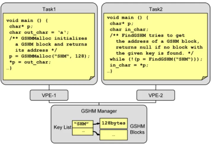
C runtime library, except that an addition key is required for each GSHM block so that the communicating tasks can refer to the same block. An example is shown in figure 6. The example shows two tasks which communicate through a GSHM block which is identified through the key string “SHM”. Inside the simulator, all the shared memory blocks are centrally managed by the GSHM manager which keeps a list of them.
VPE-1 Task1
void main () { char* p;
char out_char = ‘a‘; /** GSHMMalloc initializes
a GSHM block and returns its address */ p = GSHMMalloc(“SHM“, 128); *p = out_char; …} VPE-2 Task2 void main () { char* p; char in_char;
/** FindGSHM tries to get the address of a GSHM block, returns null if no block with the given key is found. */ while (!(p = FindGSHM(“SHM“))); in_char = *p; …} GSHM Manager … “SHM” 128bytes … Key List GSHM Blocks
Figure 6: Generic Shared Memory Example
The above example shows a scenario where the data is passed by value, which mostly occurs in multi-processor sys-tems where each parallel task has its own address space and data must be copied between tasks explicitly. Nonetheless, the use of the GSHM can be much more flexible. Since the user provided application binaries are loaded into one sulation process, all tasks running in the HVP simulator im-plicitly share one common address space. This implies that pointers can also be transfered between tasks without being invalidated, which gives an execution environment similar to a SMP (Symmetric Multiprocessing) machine where the processors share the same address space.
In the HVP, programmers have the freedom of choosing the most suitable communication mechanism for the appli-cation. Moreover, this flexibility is also helpful for code par-titioning, because the programmer does not have to com-pletely convert the implicit communications to explicit ones in order to test the functionality of the parallelized appli-cation. The HVP provides a relaxed test environment, in which partially partitioned prototypes can be simulated and used as intermediate steps towards a cleanly parallelized ap-plication.
Finally, it needs to be mentioned that the GSHM itself just provides a primitive but easy-to-use way for sharing data between tasks in the HVP. How to transfer the data in target still depends on the implementation of the real platform.
4.3
User Interface
A GUI is provided by the HVP simulator, which can be used to configure the platform, control the execution of the simulation, display runtime statistics for both VPEs and tasks, and visualize the graphical and the text information produced by the application.
Figure 7 shows a screen shot of the HVP GUI with a parallel H.264 decoder application running in the simulator.
HVP Task List VPE Task List VPE Usage Info VPE Configuration Virtual Peripheral Simulation Control Platform Config
Figure 7: HVP User Interface
The configuration of the abstract MPSoC platform as well as the task to VPE mapping can be done by just mouse clicks and drag-and-drops. Alternatively, the configuration can also be loaded from a simple XML file which can be easily created. This makes it possible that the user can automate the high-level software exploration procedure by preparing all the configuration files according to the scenarios to be explored in advance and executing the simulations in batch mode. During the simulation, the GUI also displays statistic information like the overall VPE usage and the VPE usage of each individual task.
In the host machine, the GUI runs in a separate thread in order to avoid interfering the SystemC thread directly. The communication and the synchronization between them is re-alized throughmutexesandmessagesin the host machine.
5.
PROGRAMMING SUPPORT
As a platform focused on supporting programmers, the HVP comes with a software tool suite for application devel-opment, which mainly includes:
• An API for application programming, which enables inter-task communication/synchronization and the in-teraction with the VPE; and
• A code generation toolchain for compiling the source code of native tasks.
The programming language supported by the tool suite is C. This is mainly due to the fact that C is until today the most used programming language for embedded software development.
5.1
HVP API
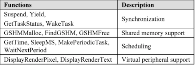
In early design stage, it is normal that the low-level soft-ware, e.g. OS, is not determined or available. In order to enable application programming, the HVP provides a small number of API functions for developers, which enable the communication and the synchronization between tasks, the interaction with the VPE, and the access to the virtual pe-ripherals. The interface is defined in C, and a short summary of the available functions is given in table 1.
It can be seen that advanced features like message queue are not available in the HVP, and the functions given are primitive in terms of their functionality. This is intended by the HVP for several reasons. First, the number of func-tions is kept small so that the programmer does not need
Virtual peripheral support DisplayRenderPixel, DisplayRenderText
Scheduling
Shared memory support Synchronization Description
GetTime, SleepMS, MakePeriodicTask, WaitNextPeriod
GSHMMalloc, FindGSHM, GSHMFree Suspend, Yield,
GetTaskStatus, WakeTask Functions
Virtual peripheral support DisplayRenderPixel, DisplayRenderText
Scheduling
Shared memory support Synchronization Description
GetTime, SleepMS, MakePeriodicTask, WaitNextPeriod
GSHMMalloc, FindGSHM, GSHMFree Suspend, Yield,
GetTaskStatus, WakeTask Functions
Table 1: HVP API Functions
much effort to learn them, and thus can easily start pro-gramming. Second, the functionality is generic and simple, through which the application source code can be kept as much HVP independent as possible. Once the target plat-form is finished, the code developed on the HVP should be able to be reused with a minimum amount of additional ef-fort.
The virtual peripheral functions are provided to visual-ize data in graphic and text format. For programmers, this is not the only way supported by the HVP to get output from the application running in the simulator. Host I/O likefreadandprintf, can be directly used by native tasks without changing the code. However, tasks running in ISS must rely on the underlying instruction-set simulator to per-form I/O operations. The difference between both kinds of tasks will be discussed in the next section.
5.2
Task Programming
Given the HVP API, writing softwares for running on the HVP is mostly like normal C application development, ex-cept that the code generation flow is different from that of a host application. Instead of being compiled to native exe-cutables, tasks must be given to the HVP as shared libraries, because the simulator does not contain any software behav-ior. Besides, as it is mentioned in section 3, tasks can be simulated in two ways, either natively or using an ISS. The differences in the tool requirement of the both approaches are summarized in table 2.
Required Target Not needed ISS Task Not needed Native Required Native Task
Extra ISS wrapper Compiler Code Instrumentation Required Target Not needed ISS Task Not needed Native Required Native Task
Extra ISS wrapper Compiler
Code Instrumentation
Table 2: Difference Between Native and ISS Tasks
From the table, it can be seen that the code generation of the native task requires an additional instrumentation pro-cedure compared to that of the ISS task, whose reason will be discussed later in section 5.2.1. Apart from that, extra wrappers are needed by the ISS tasks in order to instantiate ISS to execute the cross compiled target binaries as will be explained in 5.2.2.
5.2.1
Native Task
The native task supported by the HVP provides develop-ers a processor independent way to run their applications which is helpful when the target platform is still undefined. In order to allow user applications to run in the SystemC based simulator, several issues need to be solved here.
C applications have their ownmainfunctions, which will conflict not only with the one in the SystemC kernel but
also with each other, if they are directly linked together. This problem is solved in the HVP by compiling the user applications into shared libraries and using the task modules in the simulator as loader to load them dynamically before the simulation starts.
Moreover, pure C code is natively executed in a SystemC simulation without advancing the clock, i.e. no time is spent in the code, which does not reflect the real behavior of the application. Normally, programmers are required to manu-ally annotate the source code by inserting calls of the Sys-temC wait function in order to let the software consume simulation time. However, since such approaches introduce extra constructs, which are irrelevant to the application, into the source, the reusability of the code is reduced. Besides, estimating the execution time of software requires deep ar-chitecture knowledge; it is therefore difficult for average ap-plication developers to do it without investigating big effort. For these reasons, the HVP provides a user transparent and target independent solution for the code generation of native tasks. The complete flow is shown in figure 8.
LLVM C-Frontend hello.so void main () { printf(“hello\n”); } HVP Code Instrumentor Native Backend Code Opti.
Figure 8: Native Task Code Generation
The tools are developed based on the LLVM compiler framework [16]. A code instrumentor is inserted after the code optimization, which automatically inserts function calls for consuming simulation time. The behavior of the inserted function is very simple. It first consumes time and then checks if the time slot granted by the VPE is used up. In case of yes, it will switch the status of the task to READY, send out an event to inform the VPE of the change and start waiting for the next TASK_RUN event. Otherwise, the execution of the task just continues.
For the computation of the elapsed simulation time, since the HVP is focused on high-level functional simulation and no specific processor information is available here, we sim-plify the calculation by assuming that each VPE uses one clock cycle to perform a C level operation like an addition. The instrumentation is done per basic block so that a very high simulation speed can be achieved.
Finally, it needs to be mentioned here that the whole flow does not require any manual code annotation, the C source code is kept intact and can thus be further reused. In the simplest case, a sequential application can be brought to the HVP through just replacing the native compiler with the HVP toolchain.
5.2.2
ISS Task
The second alternative provided by the HVP to run an application is using an ISS. This is supported mainly for the early MPSoC design stage when the overall architecture of the target platform is still under design, but the use of certain processor is already determined. Besides, the com-bination of the ISS tasks and the abstract OS model in the VPE allows the developer to early evaluate the application behavior as if an OS is available, even though the real OS for the target processor would be finished much later in the design. Of course, for both cases, an ISS is needed before-hand.
same as a typical target-compilation flow, where a cross-compiler is used. Since the target binary will be executed by an instruction-set simulator, assembly code is also al-lowed here, which gives the programmer more flexibility in writing the application.
Nevertheless, in order to control the instantiation and the execution of the ISS, an extra wrapper is required, which is mainly responsible of instantiating the ISS, stepping the ISS according to the event sent from the VPE and rerouting all accesses to the shared memories to the corresponding GSHM blocks.
Figure 9 depicts the concept how the ISS is embedded into the HVP simulator. In the example, the accesses to the shared memory region of the target processor is intercepted by the wrapper and then rerouted through the VPE to the corresponding GSHM block. In this way, the ISS task is able to communicate with other tasks in the simulator.
Task Module ISS_Wrapper.so ISS Instance Local MEM Shared MEM ISS Instance Local MEM Shared MEM VPE GSHM Manager … “ISS” Real Shared MEM … Key List GSHM Blocks
Figure 9: ISS Embedded in the HVP simulator
The ISS wrapper is natively compiled into a shared li-brary. From the VPE’s point of view, an ISS task actually looks the same as a native task, because they both use the same TLM interface to interact with the VPE; and hence running them in one simulation at the same time is also al-lowed in the HVP. Currently, we have developed wrappers for the ISS generated by the LISATek processor designer [3]. Other instruction set simulators can also be supported, as long as they can be controlled by an ISS wrapper. Besides, the wrapper is application independent; therefore its devel-opment is a one time effort. Once a wrapper is developed for an ISS, it can be reused for different applications.
5.3
Debug Method
One advantage of using the HVP for parallel application development is that debugging is much simpler than that is in a real multiprocessor machine. Since the simulation is based on SystemC and executes in one thread, the behav-ior of the application is independent from the host machine and thus is fully deterministic. Besides, there is no need for special debuggers in order to debug native tasks. The in-strumentation process in their code generation flow does not destroy the source level debug information. To debuggers, they look just like normal host applications. Therefore, the programmer can use any host debugger like GDB to connect to the simulation thread and debug the code.
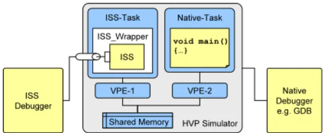
For ISS tasks, the problem is a little bit more compli-cated. Their debugger support depends on the used ISS and its wrapper. The ISS must first support the connec-tion from a debugger; and the wrapper needs to be imple-mented in a way that it can block the simulation and wait for the connected debugger to finish the user interaction. The LISATek generated simulator and the corresponding wrapper we have implemented fulfill the above mentioned
Native Debugger e.g. GDB ISS Debugger HVP Simulator VPE-1 VPE-2 Native-Task void main() {…} Shared Memory Shared Memory ISS-Task ISS_Wrapper ISS
Figure 10: Debugger Usage with the HVP
requirements. Thus, tasks running in the ISS can also be debugged in the HVP. In a mixed simulation, where ISS tasks are executed together with native tasks, both the ISS debugger and the host debugger can be used concurrently as depicted in figure 10. The host debugger is directly con-nected to the simulator for debugging native tasks; at the same time, the debugger for the ISS is connected through a channel which is instantiated by the wrapper.
In addition to the source-level debugging, the HVP also provides facilities for monitoring system level events occurred in the simulator. For example, the user can use the GUI to enable the generation of VCD trace files which record the time and the duration of the activation of all tasks. This gives the developer an overview on the execution of the sim-ulated applications.
6.
CASE STUDY
In this section, the results from the case study performed on several MPSoC platforms will be discussed. The target application is an H.264 baseline decoder whose sequential C implementation is given at the beginning. The goal is to develop parallelized decoders for the target platforms.
6.1
Application Partitioning
The application parallelization is done at high-level, as it is suggested by the design flow proposed in section 1. Since the data communication between processors is normally ex-pensive in MPSoCs, the granularity of the parallelism to be explored in the target application is aimed at coarse-grained task level.
First, the standard itself is analyzed. An H.264 video frame is composed of a number of small pixel blocks called Macro-Blocks (MBs), and the codec exploits both temporal and spatial redundancy of the video input and compresses the data MB by MB. According to this, we parallelize the de-coder by creating multiple MB dede-coder tasks which work on different MBs at the same time during the decoding process. Figure 11 shows the structure of the parallelized decoder and the data transfer between the tasks.
The implementation of the parallel decoder follows the master-slave parallel programming paradigm. There is a
Main Task which is the master and responsible for parsing
the encoded stream and preparing the data for decoding each MB. Once the MB data is ready, theMB Decoderslave tasks are activated. Each MB Decoder works on the input data passed by the master and decode one MB a time. Beside the MB data which is passed from the master to the slave tasks, a Frame Storeis also shared between the tasks for storing the decoded frames. Since it is read/written by the tasks through out the decoding process, it must be allocated
Main Task MB Decoder0 … MB Decodern … Frame Store Frame Store MB Data MB Data Shared data Task
Figure 11: Parallelized H.264 Baseline Decoder
in a memory region which is visible for all. Therefore, the parallelized decoder explicitly put the frame store in a big block of GSHM in the HVP simulator.
After the parallelization, the modified decoder is natively simulated in the HVP simulator. To test its functionality, a QCIF format (176 x 144 resolution) H.264 video file en-coded with the baseline profile is used as input. The result is checked both subjectively through the video directly dis-played in the virtual peripheral window as it is shown in figure 7, and objectively against the output produced by the sequential version decoder. Both indicate that the result is correct.
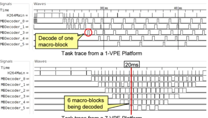
The effect of the parallelization can also be seen from the VCD traces dumped by the simulator. Figure 12 shows two task traces generated by the execution of the parallelized decoder in a 1-VPE and a 7-VPE platform. It can be clearly seen that MBs are decoded one after another in the 1-VPE platform; but in the 7-VPE platform, 6 MBs can be decoded at the same time (e.g. at 20ms).
Task trace from a 1-VPE Platform
Task trace from a 7-VPE Platform Decode of one
macro-block
6 macro-blocks being decoded
20ms
Figure 12: Task Trace Comparison
Compared to host based multiprocessor programming meth-ods such as POSIX threads, writing parallel applications on the HVP is easier in several aspects. First, the code needed for synchronization and communication is much simpler, due to the simplicity of the API and the fact that the SystemC based simulator does not require complex memory protec-tion mechanisms to be implemented in the applicaprotec-tion. Sec-ond, since the behavior of the simulator is deterministic, it is easier to find a problem than in a host workstation where the parallel application behaves differently in each execution.
6.2
Speedup Estimation
At a high abstraction level, it is difficult for the HVP to give an estimation of the absolute execution time of the application without the knowledge of the target platform. However, since the simulation time is calculated based on the number of the C level operations analyzed from the source
0 0.5 1 1.5 2 2.5 3 1 2 3 4 5 6 7 No. VPEs S pe e dup (x) 1000000 100000 10000 1000 100 Quantum Size (ns)
Figure 13: Estimated Speedup
code, a speed comparison between the sequential and the parallelized decoder is still possible, which gives a relative measure of the parallelization result.
To estimate the speedup, the parallelized decoder is sim-ulated on the HVP with different VPE numbers. Since no target platform information is considered at this level, the VPEs are all configured with the same parameter, which re-sembles a symmetric multiprocessor platform. Besides, as it was mentioned earlier, that the HVP’s implementation follows the TLM2.0 temporal decoupling coding style. Dif-ferent values of the time quantum are used so as to find the best compromise between the simulation speed and the reli-ability of the estimation result. Figure 13 shows the results of the speedup estimation.
It can be seen from the curves that the size of the time quantum has a big influence on the result. In most cases, the use of multiple VPEs shows a speedup which saturates at the use of 4 VPEs and has a maximum between 2.2 and 2.5. However, when the time quantum is 1M, there is only slow down measured by using multiple VPEs. This can ex-plained by the unnecessary synchronization overhead intro-duced by the temporal decoupling. For instance, if a task fails to acquire a spinlock, it has no chance to acquire the lock within the current time quantum because of the tem-poral decoupling, but, in a real platform, the lock can be acquired anytime in the execution. In such case, the rest of the time quantum is wasted in synchronization. 1
Theoret-ically, the smaller the quantum size is, the more reliable the simulation result is. Unfortunately, it cannot be decreased infinitively; figure 14 depicts its influence on the simulation speed which is measured in the unit of Million Operations Per Second (MOPS).2
All the measurements are done in a workstation with 8GB RAM and four CPUs each clocked at 2.67GHz.
The trend is clear that the simulation speed decreases when the time quantum is reduced. But, with the size of 10 000, the HVP gives an estimation result which is close to those with the smaller ones, and sacrifices only a little speed. Therefore, this value is used for the experiments in the following sections.
6.3
Target Platforms
In the case study, we use several in-house MPSoC plat-forms as targets, which include both homogeneous and het-erogeneous platforms. Table 3 gives a summary of their architecture:
1
The details of the temporal decoupling is out of the scope of this paper; a complete introduction of it can be found in the TLM2.0 user manual [21].
2
1 10 100 1000 10000 1,000,000 100,000 10,000 1,000 100 Quantum Size (ns) S p eed (M O P S ) Loga ri thm ic S cal e 1 2 3 4 5 6 7 No. VPEs
Figure 14: Native Simulation Speed
Not available Not available Available OS Bus Mem PE SimpleBus Local+Shared 1×RISC+ n×VLIW MP-RISC/VLIW SimpleBus Local+Shared n×RISC MP-RISC AMBA Shared n×ARM9 MP-ARM Not available Not available Available OS Bus Mem PE SimpleBus Local+Shared 1×RISC+ n×VLIW MP-RISC/VLIW SimpleBus Local+Shared n×RISC MP-RISC AMBA Shared n×ARM9 MP-ARM
Table 3: Target Platform Summary
Except for the ARM9 processor which is a third party PE and has an instruction-accurate ISS provided, the RISC and the VLIW processors are both developed in-house. A com-mon base instruction-set is shared by them, but the VLIW processor is capable of issuing 4 instructions per cycle. Their cycle accurate processor models are both developed by the LISATek processor designer. Since no hardware prototype is built, VPs are developed in order to simulate the platforms and execute the application.
6.4
Target Software Development
Since the application has already been functionally parti-tioned, the focus of the target software development is on the utilization of the communication and the synchronization services of the target platforms. The effort is very limited compared to the whole decoder. The parallelized decoder has a total of≈6500LOC(Lines of Code). The numbers of theLOC changed for the target platforms are summarized in table 4. The reuse factor is calculated by the following formula:
ReuseF actor= ((LOCT otal−LOCChanged)÷LOCT otal)×100%.
ReuseFactor LOCChanged 99% ≈30 MP-RISC/VLIW 99% ≈30 MP-RISC 97% ≈200 MP-ARM ReuseFactor LOCChanged 99% ≈30 MP-RISC/VLIW 99% ≈30 MP-RISC 97% ≈200 MP-ARM
Table 4: Code Reuse Factor
The table shows a high reuse factor of the code early de-veloped with the HVP. The MP-ARM platform has a light-weight OS running on top of it. Most of the changes done for its parallel decoder are added lines for the initialization and the configuration of the OS. The rest is needed for chang-ing the communication and the synchronization mechanism. Semaphores are instantiated for synchronizing the tasks. Be-sides, since the platform has a shared memory architecture, the use of the explicitly shared memory (i.e. the GSHM in the HVP), is no more necessary. Themalloc/freefunctions of the C library are used instead, which requires only a few lines of changes.
The MP-RISC and the MP-RISC/VLIW platforms have a non-uniform memory architecture. Each processor has its own local memory; and one platform has a block of mem-ory shared by all processors. In this case, the modifications are done mainly for relocating the data objects which origi-nally reside in the GSHM blocks of the HVP to the shared address region of the target platforms. Besides, spinlocks are used for the synchronization of the tasks. Overall, much less code modifications are required compared to that of the MP-ARM platform, because no OS needs to be configured here.
The functional test of the developed parallel decoders on the virtual platforms is rather problem-free. Since the de-coding behavior has already been tested on the HVP, there is no need to look at the codec itself. The problems oc-curred in this stage are mostly related to the code changed for the communication and the synchronization. Once the tasks correctly work together, the whole decoder produces the correct result.
For the MP-RISC/VLIW platform, the task-to-PE map-ping is done as follows: the Main Task is assigned to the RISC PE, and theMB Decoders are executed on the VLIW PEs. Since the RISC PE is developed first, the target soft-ware development of the heterogeneous platform is first done partially in the HVP before the complete VP is ready. An ISS was used to run the RISC target binary, and the MB
Decodersare executed natively.
6.5
HVP/VP Result Comparison
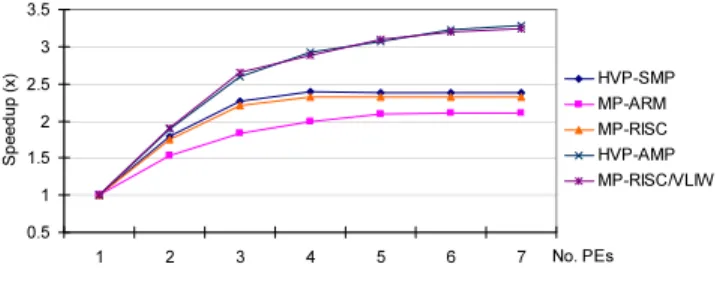
Figure 15 shows the speedup curves measured from the HVP and the VPs. The curve HVP-SMP is the predicted speedup on homogeneous platforms. Compared to the result from the MP-RISC platform, the speedup results are very close. Nonetheless, the measurements from the MP-ARM platform are lower than estimated, because there is an OS running, which requires extra processor cycles.
0.5 1 1.5 2 2.5 3 3.5 1 2 3 4 5 6 7 No. PEs S p e edu p (x) HVP-SMP MP-ARM MP-RISC HVP-AMP MP-RISC/VLIW
Figure 15: Speedup Result Comparison
In the other HVP configuration, the VPEs running MB Decoders are set to run at a higher speed so as to simulate the use of the VLIW PEs. Here, we assume that the 4-issue processor is able to achieve an average IPC (Instruction Per Cycle) number of 1.7, which is based on the a-priori knowledge of the developer of the compiler. The results are shown in curveHVP-AMP. It can be seen that the HVP has well estimated the speedup achieved by the heterogeneous platform.
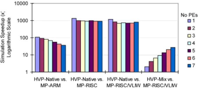
Moreover, the simulation speed of the HVP is much faster than that of the VPs. A comparison between them is given in figure 16. The simulation time used to decode the same amount of video frames is compared here. Since more than 97% of the code is identical, the comparison shows the speed
1 10 100 1000 10000 HVP-Native vs. MP-ARM HVP-Native vs. MP-RISC HVP-Native vs. MP-RISC/VLIW HVP-Mix vs. MP-RISC/VLIW S im u la ti o n S p e e d u p ( x ) L o g a ri th m ic S c a le 1 2 3 4 5 6 7 No PEs
Figure 16: Simulation Speed Comparison
difference between the platforms given the same high-level behavior is simulated.
The VP of the MP-ARM platform is built with instruc-tion accurate (IA) simulators; the RISC and the MP-RISC/VLIW platforms are simulated with cycle accurate (CA) ones. From the figure, it can be seen that the na-tive HVP simulation is in general one to two orders of mag-nitude faster (35x-110x) than the IA platform and two to three orders of magnitude faster (690x-1338x) than the CA platforms.
It is mentioned in the previous section, that the RISC code of the heterogeneous platform is first tested in the HVP by mixing the use of ISS and native simulation. The speed comparison of this scenario is shown by the HVP-Mix vs.
MP-RISC/VLIWcolumns. Here, when more PEs are involved,
the portion of the natively simulated behavior increases, and hence more speedup can be observed. Since the ISS is the bottleneck, the overall speedup is around one order of mag-nitude (2x-27x) in this mode, not as much as that of the pure native simulation. Nonetheless, the involvement of the ISS means for the programmer that the target software de-velopment can be started earlier, which is sometimes more important than the simulation speed.
7.
CONCLUSION & OUTLOOK
In this paper, a high-level virtual platform is presented, which aims to support the MPSoC software development in a very early stage. The goal is achieved by providing a set of tools for the abstract simulation of MPSoCs and the corresponding software development. With the HVP, programmers can start developing C code without details of the final target platform. The results show that the code developed on the HVP is highly reusable, and the simulation speed is much faster compared to VPs.
In future, we plan to improve the estimation of the sim-ulation time so that programmers can better examine the application performance with the HVP. In the meantime, we also plan to use the HVP to develop software for platforms with HW accelerators and/or fully distributed memories.
8.
REFERENCES
[1] Y. Ahn, K. Han, G. Lee, H. Song, J. Yoo, K. Choi, and X. Feng. SoCDAL: System-on-Chip Design AcceLerator.
ACM Trans. Des. Autom. Electron. Syst., 13(1):1–38, 2008.
[2] L. B. Brisolara, M. F. S. Oliveira, R. Redin, L. C. Lamb, L. Carro, and F. Wagner. Using UML as Front-end for Heterogeneous Software Code Generation Strategies. In
DATE ’08, New York, NY, USA, 2008. ACM.
[3] CoWare. Processor Designer. http://www.coware.com/products.
[4] P. Destro, F. Fummi, and G. Pravadelli. A Smooth Refinement Flow for Co-designing HW and SW Threads. In
DATE ’07, 2007.
[5] A. Donlin. Transaction Level Modeling: Flows and Use
Models. InCODES/ISSS 2004, pages 75–80, Sept. 2004.
[6] T. Furukawa, S. Honda, H. Tomiyama, and H. Takada. A Hardware/Software Cosimulator with RTOS Supports for
Multiprocessor Embedded Systems. InICESS ’07, pages
283–294, Berlin, Heidelberg, 2007. Springer-Verlag. [7] D. D. Gajski, J. Zhu, R. Domer, A. Gerstlauer, and
S. Zhao.SpecC: Specification Language and Methodology.
Springer-Verlag New York, Inc., 2000.
[8] J. Ganssle. 500 Embedded Engineers Have Their Say About Jobs, Tools. EETimes Europe, January 2009. http://www.eetimes.eu/design/213000236;.
[9] P. Gerin, X. Gu´erin, and F. P´etrot. Efficient
Implementation of Native Software Simulation for MPSoC.
InDATE ’08, 2008.
[10] A. Gerstlauer, H. Yu, and D. D. Gajski. RTOS Modeling
for System Level Design. InDATE ’03, 2003.
[11] C. Haubelt, T. Schlichter, J. Keinert, and M. Meredith. SystemCoDesigner: Automatic Design Space Exploration
and Rapid Prototyping from Behavioral Models. InDAC
’08, pages 580–585, New York, NY, USA, 2008. ACM.
[12] T. Kempf, M. Doerper, R. Leupers, G. Ascheid, H. Meyr, T. Kogel, and B. Vanthournout. A Modular Simulation Framework for Spatial and Temporal Task Mapping onto
Multi-processor SoC Platforms.Date ’05, 2005.
[13] T. Kempf, K. Karuri, S. Wallentowitz, G. Ascheid, R. Leupers, and H. Meyr. A SW Performance Estimation Framework for Early System-Level-Design Using
Fine-Grained Instrumentation. InDATE ’06, 2006.
[14] M. Krause, D. Englert, O. Bringmann, and W. Rosenstiel. Combination of Instruction Set Simulation and Abstract RTOS Model Execution for Fast and Accurate Target
Software Evaluation. InCODES/ISSS ’08, 2008.
[15] S. Kwon, Y. Kim, W.-C. Jeun, S. Ha, and Y. Paek. A Retargetable Parallel-Programming Framework for MPSoC.
ACM Trans. Des. Autom. Electron. Syst., 13(3):1–18, 2008.
[16] C. Lattner and V. Adve. LLVM: A Compilation Framework
for Lifelong Program Analysis & Transformation. InCGO
’04, 2004.
[17] S. Mahadevan, K. Virk, and J. Madsen. ARTS: A SystemC-Based Framework for Multiprocessor
Systems-on-Chip Modelling.Design Automation for
Embedded Systems, 11(4):285–311, December 2007.
[18] G. Martin. Overview of the MPSoC Design Challenge. In
DAC ’06, pages 274–279, 2006.
[19] T. Meyerowitz, A. Sangiovanni-Vincentelli, M. Sauermann, and D. Langen. Source-Level Timing Annotation and
Simulation for a Heterogeneous Multiprocessor. InDATE
’08, March 2008.
[20] OSCI. Open SystemC Initiative. http://www.systemc.org. [21] OSCI. TLM-2.0 User Manual.
http://www.systemc.org/downloads/standards.
[22] K. Popovici, X. Guerin, F. Rousseau, P. S. Paolucci, and A. A. Jerraya. Platform-Based Software Design Flow for
Heterogeneous MPSoC.Trans. on Embedded Computing
Sys., 7(4):1–23, 2008.
[23] H. Posadas, J. ´Adamez, P. S´anchez, E. Villar, and
F. Blasco. POSIX modeling in SystemC. InASP-DAC ’06,
pages 485–490. IEEE Press, 2006.
[24] M. Thompson, H. Nikolov, T. Stefanov, A. D. Pimentel, C. Erbas, S. Polstra, and E. F. Deprettere. A Framework for Rapid System-Level Exploration, Synthesis, and
Programming of Multimedia MP-SoCs. InCODES+ISSS
’07, pages 9–14, 2007.
[25] W. Tibboel, V. Reyes, M. Klompstra, and D. Alders. System-Level Design Flow Based on a Functional Reference
for HW and SW. InDAC ’07. 44th ACM/IEEE, June 2007.