LOAD BALANCING IN MULTIBAND CDMA
Lachlan L. H.
Andrew
Department of Electrical and Electronic Engineering University of Melbourne, Parkville, Vic, 3052, Australia
L.Andrew @ee.mu.oz.au Ph. +613 9344 9208 Fax +613 9344 9188
Absrrucr-Multiband (or multi-carrier) CDMA is a promising ap- proach to increasing the capacity of CDMA systems. The MBA algo- rithm was recently proposed for allocating new calls to bands based on measured path gains. MBA introduces asymmetry between bands. This paper calculates the average other-cell interference in MBA sys- tems and shows that the system capacity can be increased by loading different bands unequally. It also investigates the interaction of band allocations in neighbouring cells.
I. INTRODUCTION
One promising approach to increasing the capacity of code division multiple access (CDMA) systems is multi- band CDMA, a hybrid of frequency division multiple access (FDMA) and CDMA [ 1-41. Like FDMA, multiband CDMA divides the available spectrum into distinct bands, and allo- cates each connection to a single band. The system is thus composed of several independent CDMA systems which can be managed as a single unit. This has been proposed for the down link of third generation systems [ 5 ] .
One of the keys to getting good performance from a multi- band system is the allocation of new calls to bands. This pa- per investigates the recently proposed Measurement Based Allocation (MBA) algorithm, based on path gain measure- ments for the arriving call, which is described in Section 11. The signal to interference ratio is calculated for arbitrary loads on the different bands in Section 111, and this is used in Sections IV and V to determine the optimal loads to allocate to each band.
11. MEASUREMENT BASED BAND ALLOCATION CDMA requires all competing users to be received at ap- proximately the same power. Power control is used to adjust users’ transmit powers to ensure this. However, users near the boundary of a cell will have a low path gain to their con- trolling base station, and thus have a high transmit power, but will have a comparatively high path gain to the neigh- bouring base stations, and thus cause undue interference. The MBA algorithm reduces this interference by separating strong users and weak users into separate bands. When a new call arrives, the band it uses is determined by its mea- sured path gain. Following [4], a group of users within a cell allocated to the same band will be called a “ring”, and the
This work was supported by the Australian Research Council.
a
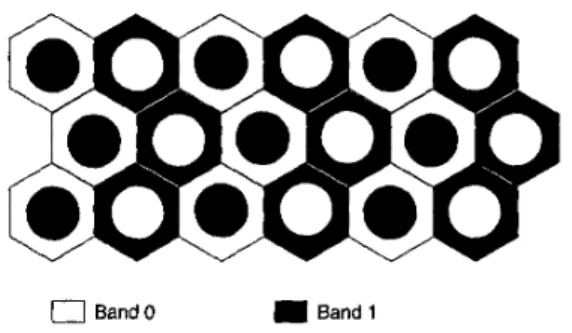
Band0 Band 1Fig. 1. Alternating arrangement with two bands in two dimensions rings containing stronger users will be referred to as the “in- ner” rings. Neglecting fading, grouping mobile stations by distance from the base station is approximately equivalent to grouping them in order of average path gain. For reasons of analytic tractability, this paper will examine systems which allocate bands based on position.
In order to reduce the interference, bands used for “weak” rings in one cell must be used for “strong” rings in neigh- bouring cells [4]. Thus there must be different “types” of cells, with different ring-to-band allocations (Figure 1). In general, there are N ! possible types of cells with N bands. In this study, two arrangements of cells will be considered: cyclic and inversion. In the “cyclic” arrangement, there are
N types of cells, corresponding to the N cyclic permutations of the bands. The “inversion” arrangement is most easily de- scribed in one dimension. In this case, there are two types of cells: in one, band 0 is allocated to the strongest users and band N
-
1 to the weakest users, with intermediate bands allocated in decreasing order of path gain; in the other, band 0 is allocated to the weakest users and band N-
1 is allo- cated to the strongest users. This will be explained in more detail in Sections IV and V.111. OTHER-CELL INTERFERENCE This section will derive expressions for the other-cell in- terference using MBA with rings of variable sizes. Follow- ing [6], the other-cell interference can be approximated by determining the ratio of other-cell to same-cell interference,
f , under a fluid approximation. With MBA, this ratio must be evaluated separately for each ring. The bands will be numbered so that in the cell of interest, ring i uses band i. Let Ici be the (constant) number of users in ring i, which is
where a is the common SIR, kT =
xi
ki is the total num-ber of users per cell, and P = ( P O , .
. .
, p ~ . . - ~ ) ~ is the vec-tor of received powers. Matrix F = ( f i , j ) is the (non-
negative) matrix of other-cell interference, which depends on the assignment of bands to rings within each cell, and
A
= diag(a0,..
.
apf-1) where ai = k i / k T is the propor-tion of the cell area covered by ring i.
When F is irreducible, Perron-Frobenius theory [7] guar- antees the existence of a unique positive eigenvector of
A ( I
+
F ) , corresponding to a dominant real eigenvalue, A.By (4), the maximum number of users which can be accom- modated per cell with SIR at least a is given by
=
s o . 0 ~ 0 , o . om
~ o , o , ,Fig. 2. Regions S0,o. go,o,oand so,o,l for the alternating arrangement
with two bands. kT = G / d . ( 5 )
proportional to the area of ring i.
For a constant SIR, different received powers, p i , must be
used for each ring. Let
SO,^
denote ring i in the cell of in- terest, cell 0. Let 3 0 , i ; j be the union of ring j of all thosecells, except cell 0, in which users in ring j transmit on band
i. The regions ~,-,,o,o and So,o,l are illustrated in Figure 2.
Assuming symmetry so that for each neighbouring cell type, j, each cell of type i will have the same number of neigh- bours of type j at the same distances, the total other-cell to same-cell interference ratio, f a , is given by
N-1
k i p i f i = k j p j f i , j , (1)
j = O
where f i , , is the interference to band i in the cell of interest from users in region & , i , j transmitting at unit power, and is
given by
The factor eb2(flu)2 x 5.455 is due to shadowing: b2 x 1/2 is the fraction of far-field shadowing, (T x 8dB is the
standard deviation of the log-normal shadowing in dB and
p =
In(lo)/lO. ThequantityR~(z,y)
= TI(~,~)/TO(Z,Y)is the ratio of the distance
from (z,y)
to the base station nearest the interfering mobile, r1 (2, y), to the distance from (2, y) to the base station of interest, T O ( Z , y).The SIR in band i is then
-
p i G-
P i G ( k i-
1)Pi -I- k i P i f i ai = (ki-
1 ) p i+
E,”&’
k j p j f i , j’
(3)where G is the processing gain per band. Taking k i
-
1 x kiin (3), the SIR for all users will be equal if
Thus X
-
1 corresponds to f in [6].Cases where F is reducible arise when the rings can be partitioned into subsets such that each subset has its own set of bands, disjoint from those of the other subsets. Rut
f i , j = 0
e$
f j , i = 0. Thus F can be transformed into a block diagonal matrix with irreducible square blocks on the diagonal, F = diag(J’1,.
. .
Fn).
Each of these blocks cor- responds tal one of the disjoint sets of bands. In this case, it is not generally possible to ensure that bands in different blocks have the same SIR. However, the capacity of the ith subset of bands is determined by the dominant eigenvalue ofF i . The capacity of the cell is determined by the smallest ca-
pacity of any of these subsets of bands, given by substituting the largest eigenvalue of F in ( 5 ) .
The potential interference reduction achievable by MBA can be calculated by solving ( 2 ) and (4) numerically. This will be done in the following sections for several geometric arrangements
.
Iv. O N E DIMENSIONAL “INVERSION” ARRANGEMENTS
When using the cyclic arrangement in one dimension, the interference reduction decreases markedly when using more than two bands. That is because the band used in a “weak” (susceptible) ring, i, in cell j will also be used in a “weak” (highly interfering) ring, i f 1, in the adjacent cells, j f 1.
An alternative arrangement of bands in one dimension is
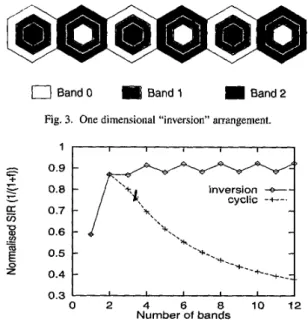
to use only two types of cells and invert the allocation in adjacent cells (Figure 3). There would thus be only two cell types, one using allocation (0, 1 , 2 , .
.
.
N-
1) and the other using (A’-
1,N
-
2 , ..
.
1 , O ) . Thus bands used in weak rings in one cell would always be used in strong rings in the two adjacent cells.For the “inversion” allocation, F will consist of (NI%]
irreducible blocks of size 2, corresponding to rings i and
N
-
1-
i, and a block of size 1 ifN
is odd. The normalisedSIR for this arrangement is shown as “inversion” in Figure 4. This shows that the performance steadily increases as the number of bands increases, although arrangements with an
ring i ring i
0
Band 0 Band 1 Band2 Fig. 3. One dimensional “inversion” arrangement.1 1 I I I I I 1 t‘ 0.8 inversion -4- v cyclic -+-. 0.3 I I I I I I 0 2 4 6 8 1 0 1 2 Number of bands
Fig. 4. Normalised SIR for one dimensional arrangements: cyclic and inversion.
odd number of bands perform consistently worse than those with an even number. For comparison, the results for the “cyclic” permutations of bands are also shown. These are obtained by solving (4) numerically when there are N cell types, in which the allocation of bands to rings follows a cyclic permutation. For example, in the case N = 4, the band allocations for the four cell types, from the strongest ring to the weakest, would be (0, 1, 2, 3), (1, 2, 3, 0 ) , (2, 3, 1, 0) and (3, 0, 1, 2). Cells of these types are then be arranged so that a “type i” cell had no neighbours of type i,
f o r i = O , 1 , 2 , 3 . A. Analytic model
Because the capacity of the system is determined by the eigenvalues of the individual blocks of A ( I
+
F ) , there is the possibility of optimising the system by adjustingA
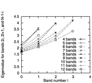
(the areas of the rings, or equivalently the offered load on the bands) to give less load to blocks with higher per-user inter- ference. The eigenvalues of each of the irreducible blocks ofI + F are shown in Figure 5 for systems with three to twelve bands. The rings with the largest eigenvalues (which limit the system capacity) are the “middle” rings: ring (N
-
1)/2 or rings N / 2-
1 and N/2.In order to quantify this, consider a one dimensional array of base stations, with spacing 1, so that ring i consists of two intervals,each of width ai/2, centred at distance ~i from the
base station, as shown in Figure 6. Bands i and N
-
1 -i will form an irreducible pair. Denote the received power in bandi by p i . Assuming the majority of the other-cell interference
comes from the immediate neighbours, and users in ring i
are all at distance ~i from the base station, the other-cell
1.16 I I I I I I 1.14 1.12 1 . 1 1.08 1.06
I P
3 bands 4 3 bands 5 6 7 8 9 10 11 12 1.04I
I I I I I I 0 1 2 3 4 5 6 7 Band number iFig. 5. Maximum eigenvalues of the irreducible blocks of I
+
F for the one dimensional inversion arrangement.Fig. 6. Base station geometry for simplified one dimensional model.
interference caused by band i is approximately
which means the SIR in band N
-
1-
i isP N - I
-
i G / bCXN-1-i = m .
a N - l - i p N - 1 - i
+
eb2(8u)2UiPi(e)
Without loss of generality, set p ~ - ~ - i = 1 for i
<
N/2.We will consider only the case when a i = a N - l - i , since the asymmetry between these rings can be countered by un- equal power allocation. Thus TN-1-i = 1/2
-
T i , andEquating all of the SIRS, ai = C X N - ~ - ~ = a, then gives
-
ai (1 + eb2(Bu)2(
Ti )mi?(E)
m‘2)hff
1-
Ti 1+
2Ti(6)
for all i
<
N / 2 . The largest rings will be the outermost and innermost ( T O x 0) (if only the interference from di- rectly adjacent cells is considered) and the smallest will be the middle ( T N / ~ x 1/4). Assuming m = 4 and = 8 dB,0.42
[
I
0.4+
5
0.38G
0.362
0.34 0.32z“
0.3 l-- v cn .--
b...
optimised +- .--... .-. cyclic -+--. B - ...-
- /
inversion .a-- 0.28‘
I I I I I 1 0 2 4 6 8 1 0 1 2 Number of bandsFig. 7. Normalised SIR for N = 3n bands for two dimensional layout with cyclic and inversion arrangements, and inversion with optimised
ring sizes.
Since these areas are approximately equal, there is limited scope for optimising performance by loading the bands un- equally.
Equation (6) also gives a useful expression for the SIR in the case of equal ring areas, ai = l/N. In this case, the SIR of the worst (middle) band isa M 0.937Glki.The coefficient
0.937 is in close agreement with the limiting value obtained by Monte Carlo simulation shown in Figure 4.
v.
TWO DIMENSIONAL “INVERSION” ARRANGEMENTS The inversion arrangement is less straightforward in two dimensions. There are now three types of cells. Bands and rings are each grouped into threes, with two “strong” rings being grouped with one “weak” ring. The band used for the weak ring in one type of cell is used for the two strong bands in the other two types. In the case of three bands, this is identical to the cyclic permutation. In general, rings 2i,2i
+
1 and N-
1-
i will use bands (24 2i+
1, N-
1-
i)in type 0 cells, (2i
+
1, N-
1-
i, 2i) in type 1, and ( N-
1-
i, 2i, 2i+
1) in type 2.Figure 7 shows the normalised SIR for the cyclic ar- rangement (“cyclic”) and inversion arrangement with equal ring sizes (“inversion”) for two dimensions. This shows
a marked decrease in performance using the inversion ar- rangement with equal ring sizes. This is because the capac- ity is severely limited by the middle rings, as can be seen in Figure 8, which shows the maximum eigenvalue of each irreducible block of I
+
F for different numbers of bands. However, this means that using unequal ring sizes can pro- vide substantial benefits.A. Analytic model
In the limit of a large number of rings, the two dimen- sional rings will reduce to concentric circles of radius r1
around the base stations (circle
C
in Figure 9). The edge effects due to hexagonal cells will be ignored. Thus the in-4.5 I I I I I I I I I 4 3.5 3 2.5 2 1.5 9bands
-*.-
10 bands - 0 - -. 11 bands -+--- 12 bands - B -- 0.5 0 0 1 2 3 4 Band number iMaximum eigenvalues of the irreducible blocks of I
+
F in two dimensions.Y
1
I
t-
Fig. 9. Interference at the basestation of one cell from a ring ‘C’ or radius
T in another cell at distance Lj .
terference from a base station in tier j is
where Lj i s the distance from a jth tier base stations to the base station of interest. For the first two tiers,
L1
=fi
andL2 = 3.
By changing to co-ordinates centred on the interfering cell and taking m = 4, (7) can be reduced to the standard integral s < a
-
b cos O)-2d0 [SI, giving the interference from a ring at radius r and width dr in any cell asAs shown in Figure 8, the capacity is limited by the other cell interference in the groups of rings with roughly equal
N
3
path gains. These will be those 213 of the way from the cell centre. That is, 2/3 of the area of the cell will be within these rings. Thus the radius is r =
JZ,
whence L l / r =and L2/r =
m.
For these bands, the powerspi will also be approximately equal.
The ratio of other cell interference from the first two tiers to the interference from h i s band is then
ao,l,aN--l a 2 , a N - 2 a 4 , a N - s ~ 6 ~ a N - 4 -1
-
a 2 N / 3
1.000 1
2nr dr
x 2.810 (8)
using the standard value of [T = 8dB. This is higher than the
value of 2.38 for the average over the whole cell. Thus, us- ing equal sized bands, this approach will perform worse than uniform allocation for large numbers of bands, as seen in Figure 7. However, using unequal band sizes this approach does provide an improvement.
The optimal ring sizes can be determined by equating the
SIR of each irreducible group of bands. (Within a group, ring sizes will be equal and the SIR will be equalised by adjusting the receive powers.) Thus by (3)
I 6
I
91
G Ui(1+
f i ) =-
kTQ I 0.200 0.133I
1.5 0.148 0.104I
0.081 1.8for all i. For the most congested bands, f 2 N / 3 x 2.810 by (8). The least congested bands are bands 0 , l and N
-
1. For band N-
1, the interference from the first tier is negligible since it comes from rings which have extremely high same- cell path gains. Thus f N - 1 , with r =JM,
can becalculated as
2 a r dr x 0.805.
Thus
indicating that the outer-most and inner-most bands should be twice as large as the middle bands.
The actual normalised SIR using optimised ring sizes is shown for 3n bands in Figure 7 as curve “optimised”. This
I
1211
0.1181
0.089I
0.069I
0.05811
2.01
TABLE I
OPTIMAL RING SIZES FOR 2-D INVERSION ARRANGEMENT.
shows a steady though slow increase as the number of bands increases, and consistently outperforms the cyclic alloca- tion. If the number of bands is not a multiple of three, then the performance is substantially worse. The actual sizes of the rings used are shown in Table I. Note that the ratio
~ ~ - ; / a 2 ~ / 3 is tending towards the predicted value of 2.1 1 . VI. CONCLUSION
When measurement based allocation [4] is used with many bands, bands must be allocated to users with widely differing path gains in neighbouring cells. This can be achieved by having three types of cells, with weak users in one type sharing the band of strong users in the two other types. The performance is optimised when the strongest and weakest bands are allocated twice as many calls as the bands with intermediate path gains.
ACKNOWLEDGEMENTS
The author thanks Dr. Stephen Hanly, Motorola’s Cellular Infrastructure Group and Nortel’s Wireless Networks group.
REFERENCES
T. Eng and L. B. Milstein, “Comparison of hybrid FDMNCDMA sys- tems in frequency selective Rayleigh fading:’ ZEEE J. Select. Areas Commun., vol. 12, pp. 938-951, June 1994.
J. R. Foerster and L. B. Milstein, “Analysis of hybrid, coherent FDMNCDMA systems in Ricean multipath fading,” ZEEE Trans. Commun., vol. 45, pp. 15-18, Jan. 1997.
T. Dean, P. Fleming, and A. Stolyar, “Estimates of multicanier CDMA system capacity,” in Proc. Winter Sim. Con$, (Washington, DC), 1998, L. L. H. Andrew, “Measurement-based band allocation in multiband CDMA,” in Proc. Znfocom ’99, (New York, NY), 1999, pp. 1364-1371. T. Ojanpera and R. E’rasad, “An overview of air interface multiple ac- cess for IMT-2000KJMTS.’’ IEEE Communications Magazine, vol. 36, pp. 82-95, Sept. 1998.
A. J. Viterbi, CDMA: Principles of Spread Spectrum Communication.
Reading, MA: Addison-Wesley, 1995.
E R. Gantmacher, Applications of the Theory of Matrices. New York: Interscience Publishers Inc. 1959.
H. B. Dwight, Tables of Integrals and Other Mathematical Data. New York: MacMillan, 1961.
pp. 1615-1622.